EP0407680A1 - Method for connecting a prefabricated scaffolding platform to a horizontal cross member, and prefabricated scaffolding platform thereto - Google Patents
Method for connecting a prefabricated scaffolding platform to a horizontal cross member, and prefabricated scaffolding platform thereto Download PDFInfo
- Publication number
- EP0407680A1 EP0407680A1 EP89870109A EP89870109A EP0407680A1 EP 0407680 A1 EP0407680 A1 EP 0407680A1 EP 89870109 A EP89870109 A EP 89870109A EP 89870109 A EP89870109 A EP 89870109A EP 0407680 A1 EP0407680 A1 EP 0407680A1
- Authority
- EP
- European Patent Office
- Prior art keywords
- support
- horizontal
- opening
- lock
- prefabricated floor
- Prior art date
- Legal status (The legal status is an assumption and is not a legal conclusion. Google has not performed a legal analysis and makes no representation as to the accuracy of the status listed.)
- Granted
Links
Images

Classifications
-
- E—FIXED CONSTRUCTIONS
- E04—BUILDING
- E04G—SCAFFOLDING; FORMS; SHUTTERING; BUILDING IMPLEMENTS OR AIDS, OR THEIR USE; HANDLING BUILDING MATERIALS ON THE SITE; REPAIRING, BREAKING-UP OR OTHER WORK ON EXISTING BUILDINGS
- E04G7/00—Connections between parts of the scaffold
- E04G7/30—Scaffolding bars or members with non-detachably fixed coupling elements
- E04G7/302—Scaffolding bars or members with non-detachably fixed coupling elements for connecting crossing or intersecting bars or members
- E04G7/303—Scaffolding bars or members with non-detachably fixed coupling elements for connecting crossing or intersecting bars or members the added coupling elements are only fixed at one of the bars or members to connect
- E04G7/305—Scaffolding bars or members with non-detachably fixed coupling elements for connecting crossing or intersecting bars or members the added coupling elements are only fixed at one of the bars or members to connect without tying means for connecting the bars or members
-
- E—FIXED CONSTRUCTIONS
- E04—BUILDING
- E04G—SCAFFOLDING; FORMS; SHUTTERING; BUILDING IMPLEMENTS OR AIDS, OR THEIR USE; HANDLING BUILDING MATERIALS ON THE SITE; REPAIRING, BREAKING-UP OR OTHER WORK ON EXISTING BUILDINGS
- E04G1/00—Scaffolds primarily resting on the ground
- E04G1/15—Scaffolds primarily resting on the ground essentially comprising special means for supporting or forming platforms; Platforms
- E04G1/154—Non-detachably fixed and secured connections between platform and scaffold
Definitions
- the present invention relates to a prefabricated floor provided with safety fastening devices to allow fixing on horizontal crosspieces of scaffolding or a similar construction with excellent fixing stability.
- a metal floor has the advantage over a traditional wooden floor of being lighter and less degrading.
- a metal floor is usually made of a folded metal sheet and / or stamped to form a resistant box.
- Each metal floor is provided with fasteners for suspension and fixing on horizontal sleepers of a construction, for example a scaffolding or a framework.
- the fasteners are usually legs intended to be placed on a horizontal crosspiece in order to thus suspend the floor.
- This method of attachment is not opposed to lifting (for example by the wind) or play which are detrimental to the stability of the floor and the safety of site personnel, people and property. This method of attachment therefore does not ensure locking on the cross-member. An imbalance of the load on the floor can therefore produce a movement of the floor and constitute a danger for site personnel.
- the invention aims to remedy the drawbacks of the known technique. Its purpose is to provide a prefabricated floor having fastening devices which not only ensure easy locking and unlocking, but also locking. reliable and automatic, capable of guaranteeing perfect seat stability on the floor.
- a floor consisting of a profile, each end of the profile being closed by a support comprising a vertical member on which are fixed two suspension hooks intended to fit a horizontal crosspiece of a construction, said vertical member being pierced with at least one opening having its horizontal axis situated in the same vertical plane as the longitudinal axis of a suspension hook.
- the aforementioned opening allows the passage of the upper part of a lock attached to the lower part of the support so as to be able to pivot in a vertical plane and so that, when the corresponding suspension hook is placed on a horizontal cross-member, the lock cooperates with the lower lateral surface of the cross member and presses against it.
- the upper part of the lock is profiled so as to always ensure the best contact between the lock and the crosspiece, regardless of the relative position of these two parts.
- an exemplary floor consisting of a metal profile 1 having a general U shape.
- the profile 1 is for example made of galvanized steel.
- the main face 11 of the profile has parallel bosses 12 serving as load distributors.
- non-slip reliefs 14 in any number.
- suspension hooks 2 intended to fit two horizontal crosspieces of a construction, for example a scaffolding, so as to suspend the floor 1.
- stiffeners are usefully provided inside the profile in order to ensure the desired stiffness combined with the desired lightness of the assembly. They each consist of a section welded between the ends of the lower wings of section 1.
- Figure 4 shows on an enlarged scale one end of the floor 1 and it shows in particular a hooking and locking device for fixing the floor on a horizontal crosspiece of a construction.
- the hooks 2 are welded to a support 3, consisting for example of a U-shaped iron, fixed at the end and inside the profile 1.
- the core of the iron 3, that is to say -to say the vertical member of the support is pierced with an opening 4 having its horizontal axis located in the same vertical plane as the longitudinal axis of one of the suspension hooks 2.
- In the opening 4 passes the upper part of a pivoting lock 6 hooked to the lower part of the support 3 so as to be able to pivot in a vertical plane.
- the lower end of the bolt 6 passes through an opening in the lower wing of the iron 3 and it is provided with a hooking head 7 constituted, for example, by a self-tapping screw with a cylindrical head.
- the attachment head 7 ensures the suspension of the lock 6 while allowing the pivoting thereof around a horizontal axis.
- a lock 6 is provided at each end of the floor 1 as shown in Figure 1. It is obvious that one could provide two locks at each end, although in practice a lock at each end is sufficient to ensure the security of the fixation.
- Unlocking a binding is also very simple.
- a pressure on the heel 62 of the latch 6 is sufficient to rotate the latter in the opposite direction to that of the movement of the needles of a watch and release it from the cross-member.
- the exemplary embodiment of the locking device according to the invention also has the advantage of allowing easy replacement of the lock 6.
- the latter is attached to the support 3 by a head formed by a screw 7, just unscrew the head 7 to remove the lock 6 and screw the head 7 into the new lock.
- the profile 1 and the latches 6 are produced in such a way that the lateral wings 15 and 16 of the profile (see fi gure 3) protect the latches 6 when they are in their raised position (unlocking position).
- the heel 62 of the latch 6 does not exceed the lower wing 17 of the profile when the latch is raised.
- the fact that the bolts 6 of a floor are thus retractable inside the profile 1 makes it possible to lay the floors on the ground, without risk of damaging them, and this facilitates the storage of the floors according to the invention.
- the main face 11 of the profile 1 has parallel bosses 12 ( Figures 1 and 2). These bosses 12 delimit between them channels 13 which facilitate the flow of rainwater, in particular through holes 18 located in the channels 13. In this way, rainwater does not stagnate on the surface of the floor and This prevents ice sheets from forming in freezing weather, which increases safety for site personnel.
Landscapes
- Engineering & Computer Science (AREA)
- Architecture (AREA)
- Mechanical Engineering (AREA)
- Civil Engineering (AREA)
- Structural Engineering (AREA)
- Mutual Connection Of Rods And Tubes (AREA)
- Floor Finish (AREA)
- Clamps And Clips (AREA)
- Ladders (AREA)
Abstract
Description
La présente invention concerne un plancher préfabriqué pourvu de dispositifs d'attache de sécurité pour permettre la fixation sur des traverses horizontales d'un échafaudage ou d'une construction similaire avec une stabilité de fixation excellente.The present invention relates to a prefabricated floor provided with safety fastening devices to allow fixing on horizontal crosspieces of scaffolding or a similar construction with excellent fixing stability.
Un plancher métallique a sur un plancher en bois traditionnel l'avantage d'être plus léger et de moins se dégrader. Un plancher métallique est habituellement constitué d'une tôle métallique pliée ou/et emboutie pour former un caisson résistant. Chaque plancher métallique est muni d'attaches pour la suspension et la fixation sur des traverses horizontales d'une construction, par exemple un échafaudage ou une ossature. Les attaches sont habituellement des pattes destinées à être posées sur une traverse horizontale afin de suspendre ainsi le plancher. Ce mode d'attache ne s'oppose pas au soulèvement (par exemple par le vent) ni au jeu qui sont préjudiciables à la stabilité du plancher et à la sécurité du personnel de chantier, des personnes et des biens. Ce mode d'attache n'assure donc pas un verrouillage sur la traverse. Un déséquilibrage de la charge sur le plancher peut dès lors produire un mouvement du plancher et constituer un danger pour le personnel de chantier.A metal floor has the advantage over a traditional wooden floor of being lighter and less degrading. A metal floor is usually made of a folded metal sheet and / or stamped to form a resistant box. Each metal floor is provided with fasteners for suspension and fixing on horizontal sleepers of a construction, for example a scaffolding or a framework. The fasteners are usually legs intended to be placed on a horizontal crosspiece in order to thus suspend the floor. This method of attachment is not opposed to lifting (for example by the wind) or play which are detrimental to the stability of the floor and the safety of site personnel, people and property. This method of attachment therefore does not ensure locking on the cross-member. An imbalance of the load on the floor can therefore produce a movement of the floor and constitute a danger for site personnel.
L'invention vise à remédier aux inconvénients de la technique connue. Elle a pour but de procurer un plancher préfabriqué ayant des dispositifs d'attache qui assurent non seulement un verrouillage et un déverrouillage aisés, mais également un verrouillage fiable et automatique, propre à garantir une parfaite stabilité d'assise au plancher.The invention aims to remedy the drawbacks of the known technique. Its purpose is to provide a prefabricated floor having fastening devices which not only ensure easy locking and unlocking, but also locking. reliable and automatic, capable of guaranteeing perfect seat stability on the floor.
Cet objectif est atteint grâce à l'invention par un plancher constitué d'un profilé, chaque extrémité du profilé étant fermée par un support comprenant un membre vertical sur lequel sont fixés deux crochets de suspension destinés à emboîter une traverse horizontale d'une construction, ledit membre vertical étant percé d'au moins une ouverture ayant son axe horizontal situé dans le même plan vertical que l'axe longitudinal d'un crochet de suspension. L'ouverture précitée permet le passage de la partie supérieure d'un verrou attaché à la partie inférieure du support de manière à pouvoir pivoter dans un plan vertical et de manière que, lorsque le crochet de suspension correspondant se trouve placé sur une traverse horizontale, le verrou coopère avec la surface latérale inférieure de la traverse et appuie contre celle-ci.This objective is achieved thanks to the invention by a floor consisting of a profile, each end of the profile being closed by a support comprising a vertical member on which are fixed two suspension hooks intended to fit a horizontal crosspiece of a construction, said vertical member being pierced with at least one opening having its horizontal axis situated in the same vertical plane as the longitudinal axis of a suspension hook. The aforementioned opening allows the passage of the upper part of a lock attached to the lower part of the support so as to be able to pivot in a vertical plane and so that, when the corresponding suspension hook is placed on a horizontal cross-member, the lock cooperates with the lower lateral surface of the cross member and presses against it.
Suivant un autre aspect de l'invention, la partie supérieure du verrou est profilée de manière à toujours assurer le meilleur contact entre le verrou et la traverse, quelle que soit la position relative de ces deux pièces.According to another aspect of the invention, the upper part of the lock is profiled so as to always ensure the best contact between the lock and the crosspiece, regardless of the relative position of these two parts.
L'invention est exposée dans ce qui suit à l'aide des dessins joints.
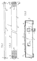
- La figure 1 est une vue en élévation d'un mode d'exécution exemplaire d'un plancher selon l'invention.
- La figure 2 est une vue en plan du plancher de la figure 1.
- La figure 3 est une coupe transversale suivant la ligne III-III de la figure 2.
- La figure 4 est une vue en coupe, à échelle agrandie, du dispositif d'accrochage et de verrouillage selon l'invention.
- La figure 5 est une vue semblable à celle de la figure 4 mais montrant le dispositif de verrouillage en position déverrouillée.
- Figure 1 is an elevational view of an exemplary embodiment of a floor according to the invention.
- Figure 2 is a plan view of the floor of Figure 1.
- Figure 3 is a cross section along line III-III of Figure 2.
- Figure 4 is a sectional view, on an enlarged scale, of the attachment and locking device according to the invention.
- Figure 5 is a view similar to that of Figure 4 but showing the locking device in the unlocked position.
Se reportant aux figures 1 à 3, on voit représenté un plancher exemplaire constitué d'un profilé métallique 1 ayant une forme générale en U. Le profilé 1 est par exemple en acier galvanisé. La face principale 11 du profilé présente des bossages parallèles 12 servant de répartisseurs de charge. Dans la surface des bossages 12 sont avantageusement formés des reliefs antidérapants 14 en nombre quelconque.Referring to Figures 1 to 3, there is shown an exemplary floor consisting of a
Aux extrémités latérales du profilé 1 sont fixés des crochets de suspension 2 destinés à emboîter deux traverses horizontales d'une construction, par exemple un échafaudage, de manière à y suspendre le plancher 1. Suivant la longueur du profilé 1, un ou plusieurs raidisseurs (non représentés) sont utilement prévus à l'intérieur du profilé afin d'assurer la raideur voulue alliée à la légèreté souhaitée de l'ensemble. Ils sont chacun constitué par un profilé soudé entre les extrémités des ailes inférieures du profilé 1.At the lateral ends of the
La figure 4 représente à échelle agrandie une extrémité du plancher 1 et elle montre en particulier un dispositif d'accrochage et de verrouillage pour la fixation du plancher sur une traverse horizontale d'une construction. On observe que les crochets 2 se trouvent soudés sur un support 3, constitué par exemple d'un fer en U, fixé à l'extrémité et à l'intérieur du profilé 1. L'âme du fer 3, c'est-à-dire le membre vertical du support, est percée d'une ouverture 4 ayant son axe horizontal situé dans le même plan vertical que l'axe longitudinal d'un des crochets de suspension 2. Dans l'ouverture 4 passe la partie supérieure d'un verrou pivotant 6 accroché à la partie inférieure du support 3 de manière à pouvoir pivoter dans un plan vertical. Dans l'exemple illustré, l'extrémité inférieure du verrou 6 traverse une ouverture ménagée dans l'aile inférieure du fer 3 et elle est munie d'une tête d'accrochage 7 constituée, par exemple, par une vis autotaraudeuse à tête cylindrique. La tête d'accrochage 7 assure la suspension du verrou 6 tout en permettant le pivotement de celui-ci autour d'un axe horizontal.Figure 4 shows on an enlarged scale one end of the
Un verrou 6 est prévu à chaque extrémité du plancher 1 comme le montre la figure 1. Il est évident que l'on pourrait prévoir deux verrous à chaque extrémité, bien qu'en pratique un verrou à chaque extrémité suffise pour assurer la sécurité de la fixation.A
La mise en place du plancher selon l'invention sur une traverse horizontale, ainsi que l'accrochage et le verrouillage sur celle-ci se font en une seule opération par le simple emboîtement des crochets de suspension 2 et de la traverse, et le verrouillage sur la traverse se fait automatiquement. Lorsque l'on pose un crochet de suspension 2 muni d'un verrou 6 sur une traverse horizontale, celle-ci soulève le verrou 6 et le fait pivoter dans le sens contraire à celui du mouvement des aiguilles d'une montre. Lorsque le verrou 6 se trouve amené dans une position telle que montrée dans la figure 5 par exemple, c'est-à-dire une position qui permet à la traverse 8 de s'engager dans l'ouverture du crochet de suspension 2, celui-ci vient reposer sur et emboîter la traverse 8 (figure 4) en basculant et en s'appuyant contre la surface de la traverse. Au moment où la traverse et le crochet de suspension se trouvent complètement emboîtés (figure 4), le verrou 6 bascule et sa face extérieure 60 vient appuyer contre la traverse 8 et verrouille celle-ci dans l'ouverture du crochet de suspension 2. Le profil incurvé du verrou 6 assure ainsi toujours un emboîtement et une fixation sans jeu qui est garante d'une parfaite stabilité du plancher suspendu et est par conséquent garante d'une totale sécurité pour le personnel de chantier, ainsi que pour les personnes et les biens, par exemple en cas de tempête.The establishment of the floor according to the invention on a horizontal cross member, as well as the hooking and locking on it are done in a single operation by the simple interlocking of the
Le déverrouillage d'une fixation se fait également d'une façon très simple. Une pression sur le talon 62 du verrou 6 suffit pour faire pivoter celui-ci dans le sens contraire à celui du mouvement des aiguilles d'une montre et le dégager de la traverse.Unlocking a binding is also very simple. A pressure on the
Le mode d'exécution exemplaire du dispositif de verrouillage selon l'invention a également pour avantage de permettre le remplacement aisé du verrou 6. En effet, comme celui-ci se trouve accroché au support 3 par une tête formée d'une vis 7, il suffit de dévisser la tête 7 pour retirer le verrou 6 et de visser la tête 7 dans le nouveau verrou.The exemplary embodiment of the locking device according to the invention also has the advantage of allowing easy replacement of the
Suivant un aspect avantageux de l'invention, le profilé 1 et les verrous 6 sont réalisés de telle manière que les ailes latérales 15 et 16 du profilé (voir fi gure 3) protègent les verrous 6 lorsque ceux-ci se trouvent dans leur position relevée (position de déverrouillage). Se reportant à la figure 5 par exemple, on voit en effet que le talon 62 du verrou 6 ne dépasse pas l'aile inférieure 17 du profilé lorsque le verrou est relevé. Le fait que les verrous 6 d'un plancher sont ainsi escamotables à l'intérieur du profilé 1 permet de poser les planchers par terre, sans risque de les détériorer, et cela facilite l'entreposage des planchers selon l'invention.According to an advantageous aspect of the invention, the
Comme décrit précédemment, la face principale 11 du profilé 1 présente des bossages parallèles 12 (figures 1 et 2). Ces bossages 12 délimitent entre eux des canaux 13 qui facilitent l'écoulement des eaux de pluie, en particulier au travers de trous 18 situés dans les canaux 13. De cette manière, les eaux de pluie ne stagnent pas sur la surface du plancher et on évite ainsi la formation de plaques de verglas par temps de gel, ce qui accroît la sécurité pour le personnel de chantier.As described above, the
Le mode de réalisation de l'invention décrit dans ce qui précède est un exemple donné à titre illustratif et l'invention n'est nullement limitée à cet exemple. Toute modification, toute variante et tout agencement équivalent doivent être considérés comme compris dans le cadre de l'invention.The embodiment of the invention described in the foregoing is an example given by way of illustration and the invention is in no way limited to this example. Any modification, any variant and any equivalent arrangement must be considered to be within the scope of the invention.
Claims (6)
Priority Applications (3)
| Application Number | Priority Date | Filing Date | Title |
|---|---|---|---|
| EP89870109A EP0407680B1 (en) | 1989-07-12 | 1989-07-12 | Method for connecting a prefabricated scaffolding platform to a horizontal cross member, and prefabricated scaffolding platform thereto |
| AT89870109T ATE102679T1 (en) | 1989-07-12 | 1989-07-12 | METHOD OF CONNECTING A PREFABRICATED SCAFFOLDING PLATFORM TO A HORIZONTAL CROSSBAR, AND PREFABRICATED SCAFFOLDING PLATFORM TO IT. |
| DE89870109T DE68913733D1 (en) | 1989-07-12 | 1989-07-12 | Method for connecting a prefabricated scaffolding platform with a horizontal cross member, and prefabricated scaffolding platform for this. |
Applications Claiming Priority (1)
| Application Number | Priority Date | Filing Date | Title |
|---|---|---|---|
| EP89870109A EP0407680B1 (en) | 1989-07-12 | 1989-07-12 | Method for connecting a prefabricated scaffolding platform to a horizontal cross member, and prefabricated scaffolding platform thereto |
Publications (2)
| Publication Number | Publication Date |
|---|---|
| EP0407680A1 true EP0407680A1 (en) | 1991-01-16 |
| EP0407680B1 EP0407680B1 (en) | 1994-03-09 |
Family
ID=8203283
Family Applications (1)
| Application Number | Title | Priority Date | Filing Date |
|---|---|---|---|
| EP89870109A Expired - Lifetime EP0407680B1 (en) | 1989-07-12 | 1989-07-12 | Method for connecting a prefabricated scaffolding platform to a horizontal cross member, and prefabricated scaffolding platform thereto |
Country Status (3)
| Country | Link |
|---|---|
| EP (1) | EP0407680B1 (en) |
| AT (1) | ATE102679T1 (en) |
| DE (1) | DE68913733D1 (en) |
Cited By (7)
| Publication number | Priority date | Publication date | Assignee | Title |
|---|---|---|---|---|
| FR2690188A1 (en) * | 1992-04-17 | 1993-10-22 | Edac | Metal scaffolding plank - has sides which have rectangular lengthwise corrugations and lower edges turned inwards and upwards |
| DE9314353U1 (en) * | 1993-09-22 | 1993-12-16 | Hans-J. Gebauer GmbH, 56727 Mayen | Working platform, preferably scaffolding for scaffolding or the like. |
| FR2702507A1 (en) * | 1993-03-08 | 1994-09-16 | Entreprose Montalev | Floor element for scaffolding. |
| EP0637660A1 (en) * | 1993-08-02 | 1995-02-08 | Gerald Merkel | Anti-lifting lock for scaffold platforms |
| GB2294495A (en) * | 1994-10-28 | 1996-05-01 | Alloy Die & Cast Ltd | Locking device for scaffolding platform |
| DE19633091A1 (en) * | 1996-08-16 | 1998-02-19 | Peri Gmbh | Dismountable facade scaffolding for exterior of building |
| FR2781534A1 (en) * | 1998-07-21 | 2000-01-28 | Entrepose Echafaudages | Lock for fixing scaffold boards onto horizontal cross member has cam cooperating with hooks on board |
Citations (5)
| Publication number | Priority date | Publication date | Assignee | Title |
|---|---|---|---|---|
| GB2058189A (en) * | 1979-08-15 | 1981-04-08 | Gkn Mills Building Serv | Releasable Fastenings |
| FR2485598A3 (en) * | 1980-06-26 | 1981-12-31 | Fap Fabrica Attrezature Prefab | Platform with lateral hooks for tubular scaffolding - incorporates triangular rings which, on rotation, prevent removal of inserted scaffolding component |
| GB2127086A (en) * | 1982-08-20 | 1984-04-04 | Alto Systems Ltd | Automatic latch for use in scaffolding structures |
| FR2573115A1 (en) * | 1984-11-09 | 1986-05-16 | Layher Eberhard | SCAFFOLDING FRAME PANEL. |
| EP0305014A2 (en) * | 1987-08-28 | 1989-03-01 | Beleggingsmaatschappij Bouwmaterieel Europa B.V. | Scaffold comprising uprights, cross members and platforms connected to the cross members |
-
1989
- 1989-07-12 AT AT89870109T patent/ATE102679T1/en not_active IP Right Cessation
- 1989-07-12 DE DE89870109T patent/DE68913733D1/en not_active Expired - Lifetime
- 1989-07-12 EP EP89870109A patent/EP0407680B1/en not_active Expired - Lifetime
Patent Citations (5)
| Publication number | Priority date | Publication date | Assignee | Title |
|---|---|---|---|---|
| GB2058189A (en) * | 1979-08-15 | 1981-04-08 | Gkn Mills Building Serv | Releasable Fastenings |
| FR2485598A3 (en) * | 1980-06-26 | 1981-12-31 | Fap Fabrica Attrezature Prefab | Platform with lateral hooks for tubular scaffolding - incorporates triangular rings which, on rotation, prevent removal of inserted scaffolding component |
| GB2127086A (en) * | 1982-08-20 | 1984-04-04 | Alto Systems Ltd | Automatic latch for use in scaffolding structures |
| FR2573115A1 (en) * | 1984-11-09 | 1986-05-16 | Layher Eberhard | SCAFFOLDING FRAME PANEL. |
| EP0305014A2 (en) * | 1987-08-28 | 1989-03-01 | Beleggingsmaatschappij Bouwmaterieel Europa B.V. | Scaffold comprising uprights, cross members and platforms connected to the cross members |
Cited By (8)
| Publication number | Priority date | Publication date | Assignee | Title |
|---|---|---|---|---|
| FR2690188A1 (en) * | 1992-04-17 | 1993-10-22 | Edac | Metal scaffolding plank - has sides which have rectangular lengthwise corrugations and lower edges turned inwards and upwards |
| FR2702507A1 (en) * | 1993-03-08 | 1994-09-16 | Entreprose Montalev | Floor element for scaffolding. |
| EP0616098A1 (en) * | 1993-03-08 | 1994-09-21 | Entrepose-Montalev | Scaffolding platform element |
| EP0637660A1 (en) * | 1993-08-02 | 1995-02-08 | Gerald Merkel | Anti-lifting lock for scaffold platforms |
| DE9314353U1 (en) * | 1993-09-22 | 1993-12-16 | Hans-J. Gebauer GmbH, 56727 Mayen | Working platform, preferably scaffolding for scaffolding or the like. |
| GB2294495A (en) * | 1994-10-28 | 1996-05-01 | Alloy Die & Cast Ltd | Locking device for scaffolding platform |
| DE19633091A1 (en) * | 1996-08-16 | 1998-02-19 | Peri Gmbh | Dismountable facade scaffolding for exterior of building |
| FR2781534A1 (en) * | 1998-07-21 | 2000-01-28 | Entrepose Echafaudages | Lock for fixing scaffold boards onto horizontal cross member has cam cooperating with hooks on board |
Also Published As
| Publication number | Publication date |
|---|---|
| DE68913733D1 (en) | 1994-04-14 |
| EP0407680B1 (en) | 1994-03-09 |
| ATE102679T1 (en) | 1994-03-15 |
Similar Documents
| Publication | Publication Date | Title |
|---|---|---|
| CA1303810C (en) | Removable skelter structure | |
| EP1525354B1 (en) | Grate for closing a drain and similar | |
| EP0099298B1 (en) | Fastening means to a building and application to the realization of scaffoldings | |
| EP2543800B1 (en) | Device for locking and unlocking at least one covering element on a frame for supporting said element | |
| EP0407680B1 (en) | Method for connecting a prefabricated scaffolding platform to a horizontal cross member, and prefabricated scaffolding platform thereto | |
| EP2363555B1 (en) | Locking/unlocking device with improved tamper resistance | |
| FR2689546A1 (en) | Device for ceiling formwork. | |
| FR3045086A1 (en) | FOLDING BODY FOR ROOF TERRACE, MODULAR BUILDING COMPRISING AT LEAST ONE FOLDING BODY AND MODULAR CONSTRUCTION COMPRISING AT LEAST TWO MODULAR BUILDINGS | |
| FR2987856A1 (en) | Support bracket for fixing cantilever structure in wall, has rod that is released from opening during displacement of body with regard to rod according to vertical direction directed to top after clamping mechanism is loosened | |
| EP1334236B1 (en) | Extensible barrier on rollers with manually extensible and retractable pivoting elements | |
| EP1160382B1 (en) | Manhole cover with theft-prevention device | |
| FR2589506A1 (en) | Device for fixing a bracket for circulation or formwork on a vertical wall of a concrete structure | |
| EP1253280B1 (en) | Device for a safety anchor | |
| FR2799478A1 (en) | DEVICE FOR CLOSING A VISIT OR INSPECTION LOOK | |
| EP0698692B1 (en) | Cover for a fire hydrant shaft | |
| FR2912171A1 (en) | Floating curtain locking device for e.g. inground swimming pool, has base including lower wing piercing through central hole for receiving compression spring adjusted by screw that is equipped with protection pin at top | |
| FR2480338A1 (en) | Safety catwalk for roofing work - includes canopy supported by pivoted uprights which can fold down to roof level | |
| FR2929306A1 (en) | V-shaped integrated lock hook for support of shuttering wall form in concrete building construction, has locking units occupying retracted position in hook and locking position and associated with overlocking units to manual unlock | |
| EP3230532B1 (en) | Assembly for roadway manhole comprising a frame, a cover and a kit allowing the cover to be hingedly mounted on the frame | |
| FR2679289A1 (en) | ANTI-SLIPPING DEVICE FOR SLIDING DOOR, ESPECIALLY DOOR, WINDOW OR THE LIKE. | |
| FR2677632A1 (en) | Slab lifter | |
| FR2696147A1 (en) | Articulation device at the bottom of a side panel of a vehicle tipper. | |
| FR2683245A1 (en) | Removable corbelled (jutting-out) platform, particularly for walking on or formwork in concrete constructions | |
| EP2365163B1 (en) | Espagnolette locking device for wings | |
| FR2867219A1 (en) | Canopy door e.g. garage door, leaf, has overall inviolability system with three anti-braking devices situated respectively close to pivoting axis, close to locking control device and in locking zone |
Legal Events
| Date | Code | Title | Description |
|---|---|---|---|
| PUAI | Public reference made under article 153(3) epc to a published international application that has entered the european phase |
Free format text: ORIGINAL CODE: 0009012 |
|
| AK | Designated contracting states |
Kind code of ref document: A1 Designated state(s): AT BE CH DE ES FR GB GR IT LI LU NL SE |
|
| 17P | Request for examination filed |
Effective date: 19910628 |
|
| 17Q | First examination report despatched |
Effective date: 19911218 |
|
| GRAA | (expected) grant |
Free format text: ORIGINAL CODE: 0009210 |
|
| AK | Designated contracting states |
Kind code of ref document: B1 Designated state(s): AT BE CH DE ES FR GB GR IT LI LU NL SE |
|
| PG25 | Lapsed in a contracting state [announced via postgrant information from national office to epo] |
Ref country code: IT Free format text: LAPSE BECAUSE OF FAILURE TO SUBMIT A TRANSLATION OF THE DESCRIPTION OR TO PAY THE FEE WITHIN THE PRE;WARNING: LAPSES OF ITALIAN PATENTS WITH EFFECTIVE DATE BEFORE 2007 MAY HAVE OCCURRED AT ANY TIME BEFORE 2007. THE CORRECT EFFECTIVE DATE MAY BE DIFFERENT FROM THE ONE RECORDED.SCRIBED TIME-LIMIT Effective date: 19940309 Ref country code: ES Free format text: THE PATENT HAS BEEN ANNULLED BY A DECISION OF A NATIONAL AUTHORITY Effective date: 19940309 Ref country code: AT Effective date: 19940309 Ref country code: SE Free format text: THE PATENT HAS BEEN ANNULLED BY A DECISION OF A NATIONAL AUTHORITY Effective date: 19940309 Ref country code: NL Effective date: 19940309 Ref country code: GB Effective date: 19940309 Ref country code: GR Free format text: LAPSE BECAUSE OF FAILURE TO SUBMIT A TRANSLATION OF THE DESCRIPTION OR TO PAY THE FEE WITHIN THE PRESCRIBED TIME-LIMIT Effective date: 19940309 Ref country code: DE Effective date: 19940309 |
|
| REF | Corresponds to: |
Ref document number: 102679 Country of ref document: AT Date of ref document: 19940315 Kind code of ref document: T |
|
| REF | Corresponds to: |
Ref document number: 68913733 Country of ref document: DE Date of ref document: 19940414 |
|
| NLV1 | Nl: lapsed or annulled due to failure to fulfill the requirements of art. 29p and 29m of the patents act | ||
| GBV | Gb: ep patent (uk) treated as always having been void in accordance with gb section 77(7)/1977 [no translation filed] |
Effective date: 19940309 |
|
| PLBE | No opposition filed within time limit |
Free format text: ORIGINAL CODE: 0009261 |
|
| STAA | Information on the status of an ep patent application or granted ep patent |
Free format text: STATUS: NO OPPOSITION FILED WITHIN TIME LIMIT |
|
| 26N | No opposition filed | ||
| PGFP | Annual fee paid to national office [announced via postgrant information from national office to epo] |
Ref country code: CH Payment date: 19960712 Year of fee payment: 8 |
|
| PGFP | Annual fee paid to national office [announced via postgrant information from national office to epo] |
Ref country code: BE Payment date: 19970612 Year of fee payment: 9 |
|
| PGFP | Annual fee paid to national office [announced via postgrant information from national office to epo] |
Ref country code: FR Payment date: 19970730 Year of fee payment: 9 |
|
| PG25 | Lapsed in a contracting state [announced via postgrant information from national office to epo] |
Ref country code: CH Free format text: LAPSE BECAUSE OF NON-PAYMENT OF DUE FEES Effective date: 19970731 Ref country code: LI Free format text: LAPSE BECAUSE OF NON-PAYMENT OF DUE FEES Effective date: 19970731 |
|
| PGFP | Annual fee paid to national office [announced via postgrant information from national office to epo] |
Ref country code: LU Payment date: 19970804 Year of fee payment: 9 |
|
| REG | Reference to a national code |
Ref country code: CH Ref legal event code: PL |
|
| PG25 | Lapsed in a contracting state [announced via postgrant information from national office to epo] |
Ref country code: LU Free format text: LAPSE BECAUSE OF NON-PAYMENT OF DUE FEES Effective date: 19980712 |
|
| PG25 | Lapsed in a contracting state [announced via postgrant information from national office to epo] |
Ref country code: BE Free format text: LAPSE BECAUSE OF NON-PAYMENT OF DUE FEES Effective date: 19980731 |
|
| BERE | Be: lapsed |
Owner name: S.A. TRAVHYDRO ECHAFAUDAGES Effective date: 19980731 |
|
| PG25 | Lapsed in a contracting state [announced via postgrant information from national office to epo] |
Ref country code: FR Free format text: LAPSE BECAUSE OF NON-PAYMENT OF DUE FEES Effective date: 19990331 |
|
| REG | Reference to a national code |
Ref country code: FR Ref legal event code: ST |