EP0406771B1 - Aufzugsgeschwindigkeitsbefehlssystem - Google Patents
Aufzugsgeschwindigkeitsbefehlssystem Download PDFInfo
- Publication number
- EP0406771B1 EP0406771B1 EP90112603A EP90112603A EP0406771B1 EP 0406771 B1 EP0406771 B1 EP 0406771B1 EP 90112603 A EP90112603 A EP 90112603A EP 90112603 A EP90112603 A EP 90112603A EP 0406771 B1 EP0406771 B1 EP 0406771B1
- Authority
- EP
- European Patent Office
- Prior art keywords
- velocity
- distance
- value
- acceleration
- elevator
- Prior art date
- Legal status (The legal status is an assumption and is not a legal conclusion. Google has not performed a legal analysis and makes no representation as to the accuracy of the status listed.)
- Expired - Lifetime
Links
- 230000001133 acceleration Effects 0.000 claims description 97
- 230000036461 convulsion Effects 0.000 claims description 24
- 238000000034 method Methods 0.000 claims description 13
- 230000001934 delay Effects 0.000 claims description 7
- 230000007704 transition Effects 0.000 description 13
- 238000013459 approach Methods 0.000 description 8
- 230000010354 integration Effects 0.000 description 6
- 238000004088 simulation Methods 0.000 description 6
- 238000013461 design Methods 0.000 description 5
- 230000003044 adaptive effect Effects 0.000 description 4
- 238000004422 calculation algorithm Methods 0.000 description 4
- 230000006978 adaptation Effects 0.000 description 3
- 230000006872 improvement Effects 0.000 description 3
- QWXYZCJEXYQNEI-OSZHWHEXSA-N intermediate I Chemical compound COC(=O)[C@@]1(C=O)[C@H]2CC=[N+](C\C2=C\C)CCc2c1[nH]c1ccccc21 QWXYZCJEXYQNEI-OSZHWHEXSA-N 0.000 description 3
- 230000001419 dependent effect Effects 0.000 description 2
- 238000010586 diagram Methods 0.000 description 2
- 230000004069 differentiation Effects 0.000 description 2
- 238000011084 recovery Methods 0.000 description 2
- 230000009466 transformation Effects 0.000 description 2
- 238000005303 weighing Methods 0.000 description 2
- 238000004364 calculation method Methods 0.000 description 1
- 230000015556 catabolic process Effects 0.000 description 1
- 230000008859 change Effects 0.000 description 1
- 238000006243 chemical reaction Methods 0.000 description 1
- 230000000052 comparative effect Effects 0.000 description 1
- 238000010276 construction Methods 0.000 description 1
- 230000007423 decrease Effects 0.000 description 1
- 238000006731 degradation reaction Methods 0.000 description 1
- 230000003111 delayed effect Effects 0.000 description 1
- 238000009795 derivation Methods 0.000 description 1
- 238000005516 engineering process Methods 0.000 description 1
- 206010016256 fatigue Diseases 0.000 description 1
- 230000010365 information processing Effects 0.000 description 1
- 238000012423 maintenance Methods 0.000 description 1
- 238000005259 measurement Methods 0.000 description 1
- 239000000203 mixture Substances 0.000 description 1
- 238000012986 modification Methods 0.000 description 1
- 230000004048 modification Effects 0.000 description 1
- 230000009467 reduction Effects 0.000 description 1
- 238000005070 sampling Methods 0.000 description 1
- 230000035945 sensitivity Effects 0.000 description 1
Images


Classifications
-
- B—PERFORMING OPERATIONS; TRANSPORTING
- B66—HOISTING; LIFTING; HAULING
- B66B—ELEVATORS; ESCALATORS OR MOVING WALKWAYS
- B66B1/00—Control systems of elevators in general
- B66B1/24—Control systems with regulation, i.e. with retroactive action, for influencing travelling speed, acceleration, or deceleration
- B66B1/28—Control systems with regulation, i.e. with retroactive action, for influencing travelling speed, acceleration, or deceleration electrical
- B66B1/285—Control systems with regulation, i.e. with retroactive action, for influencing travelling speed, acceleration, or deceleration electrical with the use of a speed pattern generator
Definitions
- the present invention relates to elevator systems and in particular to elevator velocity control. Still more precise, the present invention is related to a method for controlling the acceleration and deceleration of an elevator in an elevator speed dictation system.
- automatic elevator operation requires the control of elevator velocity with respect to zero or stop, at the beginning and the end of a trip, to speeds therebetween, which minimize trip time while maintaining comfort levels and other constraints.
- the time change in velocity for a complete trip is termed a "velocity profile.”
- Automatic elevator control further requires control of the distance travelled during a trip in order to accomplish a precision stop at the destination floor.
- phase-plane control for precision stopping, wherein dictated velocity is a function of the distance to go to the landing. As the distance-to-go approaches zero, the slope of the velocity/distance curve approaches infinity ( ⁇ ). Using linear control theory, it can be shown that the slope of the phase-plane curve represents the position error gain for phase-plane control and is proportional to position loop bandwidth. For the speed control loop to track the dictated velocity profile with stability, its bandwidth must be greater by a significant factor than the bandwidth of the position control loop.
- One strategy for reducing the required bandwidth is to limit the slope of the phase-plane velocity versus position profile (position error gain) to a maximum value, such that the position loop bandwidth is sufficiently lower than the velocity loop bandwidth.
- the torque producing capability of elevator motors may vary with speed due to motor current, voltage, and/or power limitations. If the drive is not capable of maintaining the acceleration limit under all conditions due to these torque limits, some means of reducing the acceleration (and hence torque) in the corresponding portions of the velocity profile must be provided without compromising operation of the drive at its limit or complicating the profile generation more than necessary.
- each segment of the velocity profile was generated at one of the limits constraining the system; viz., at maximum jerk, maximum acceleration, maximum velocity, maximum position or loop gain, or maximum motor torque.
- the acceleration portion of the velocity profile preferably was generated in an open loop manner, beginning with constant (maximum) jerk, transitioning to constant (maximum) acceleration after an acceleration limit is attained, and jerking out (negative jerk) at a constant rate to maximum (contract) velocity when the maximum velocity is nearly attained.
- US-A-4,751,984 represents a very substantial advance in the art, it also was subject to improvement, to which the present invention is directed. The disclosure of the document US-A-4,751,984 is incorporated herein by reference.
- acceleration reduction preferably is used to keep power requirements well bounded without significantly compromising flight time. This is a form of acceleration profile adaptation based on speed.
- the acceleration and jerk limits for the profile may be adjusted in accordance with available torque.
- the torque requirements may be determined from the load weighing signal, which gives the load in the cab.
- the acceleration and jerk limits for the profile can then be adjusted accordingly.
- the profile generator can be made adaptive by presetting the acceleration and jerk limits based on the load in the elevator cab. This can be done by a simple computation based on the load weight made at the beginning of a run. This could be done to permit the use of a smaller than usual drive system, if so desired.
- the dictation system of the present invention is capable of generating for output high-quality velocity and acceleration signals. It is advantageous because it is highly structured in design, tolerant of significant computational errors, and is easily modified to handle unusual situations.
- the velocity-profile generation approach of the present invention preferably:
- each segment of the velocity profile likewise is generated at one of the limits which constrain the system; viz., at maximum jerk, maximum acceleration, maximum velocity, maximum position or loop gain, or maximum motor torque.
- the acceleration portion of the velocity profile preferably is generated in an open loop manner, beginning with constant (maximum) jerk, transitioning to constant (maximum) acceleration after an acceleration limit is attained, and jerking out (negative jerk) at a constant rate to maximum (contract) velocity when the maximum velocity is nearly attained.
- the invention may be practiced in a wide variety of elevator applications utilizing known technology, in the light of the teachings of the invention, which are discussed in detail hereafter.
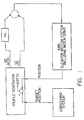
- Figure 1 is a simplified, block diagram of an exemplary embodiment of the elevator speed dictation system related to the present invention.
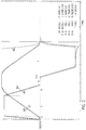
- Figure 2 is a graph of the velocity profile of the invention for an exemplary long run of an elevator car in accordance with the exemplary principles of the present invention. (It is noted that the numerical information on the lower, right side of the figure refers to the data values of the traces at the vertical cursor line located to the left side of the graphed, displayed traces; the same being true of Figs. 3-6 .)
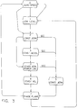
- Figure 3 is a flow chart showing the transitions between the regions of the velocity profile of Figure 2 , as well as of the velocity profiles of Figures 4-6 , with Regions 0 (zero speed) and 1 (low level phase plane) not being illustrated for simplicity purposes in the velocity profiles.
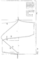
- Figure 4 is a graph of the velocity profile of the invention for an exemplary "Intermediate II" profile of the elevator car, in which the Intermediate II profile illustrates the situation wherein a transition to Region 5 occurs after a Stop Control Command (SCC).
- SCC Stop Control Command
- Figure 5 is a graph of the velocity profile of the invention for an exemplary "Intermediate I" profile of the elevator car, in which the Intermediate I profile - illustrates the situation wherein there is a transition from Region 3 to Region 5 .
- Figure 6 is a graph of the velocity profile of the invention for an exemplary short run of the elevator car.
- Figure 7 is a comparative graph of exemplary velocity and acceleration curves used in the invention to find the stopping distance.
- FIG. 1 An exemplary function block diagram of the invention is shown in Figure 1 .
- the profile generator ( PROFILE GEN .) delivers a velocity signal " VD " and an acceleration signal " AD " to an elevator control system.
- the gain " KA” is used to control the blend of the acceleration signal to the velocity signal in a feed-forward control.
- the acceleration signal may be routed directly to the motor torque control point in the motor drive.
- limiters or filters are used between the VD and AD signals and the elevator motion system (" EMS ").
- the EMS includes a position reference system, which feeds back the car position (“ POSITION ”) to the profile generator.
- the function of the profile generator is to bring the car to the target position within the acceleration and jerk constraints. These constraints may be fixed or they may be a function of available power, motor torque, etc . Just before and sometimes even during a run, the constraints may be changed.
- the profile generator is designed in a structured fashion, thereby permitting adaptation to changing circumstances, even when a run is under way.
- the overall position control system should bring the car to its destination in a minimum amount of time, without vibrations or overshoot.
- the overall positioning accuracy sought is usually better than plus-or-minus three millimeters ( ⁇ 3 mm), although plus-or-minus six millimeters ( ⁇ 6 mm) is acceptable.
- the acceleration limit is usually set by the available torque in the motor drive. However, in an oversized system, passenger comfort may determine the acceleration limit.
- Part of the torque is used to offset unbalance and friction forces.
- the other part is used to accelerate or decelerate the system mass.
- Figure 2 shows the dictated and actual velocity and acceleration for an exemplary long run. Understanding this profile set is important because all other profile sets are subsets of this one. As can be seen in Figure 2 various regions 2-7 , defined and explained more fully below, are marked.
- the profiles for the first part of the run are developed on the basis of dictated acceleration. Dictated velocity is obtained by the numerical integration of the dictated acceleration. (Henceforth, as a matter of form and for simplicity purposes, dictated velocity and acceleration typically will be referred to without the adjective "dictated” being added.)
- the actual position, velocity, and acceleration are outputs from the EMS .
- Region Definition 0 zero speed 1 low level phase plane 2 constant jerk to prescribed acceleration 3 prescribed acceleration 4 constant jerk down to constant velocity 5 jerk level after generation of SCC 6 constant speed 7 phase plane Regions " 0 ,” “ 1 ,” and “ 7 " apply to runs of all lengths. Regions 0 and 1 are not shown explicitly on the profiles illustrated in Figures 2 , etc. , and the meaning of Region 1 is explained when the phase-plane Region 7 is explained.
- Region 3 The end of Region 3 is defined when "VBASE” is reached.
- VBASE can be the base velocity or speed of the motor or a lower speed.
- VBASE is subject to some variation, and, typically, it will be close to but a bit less than the base speed of the motor involved.
- a “jerk out” is then defined in Region 4 until maximum speed is reached in Region 6 . Operation continues in Region 6 , until the stop control command ( SCC) is received.
- Region 7 is then entered.
- the velocity is commanded as a function of distance-to-go on the basis of a table of velocity versus distance built up for all travel in Regions 2-5 .
- an acceleration table is also being built. Both the velocity and acceleration tables can be weighted, so that deceleration occurs in direct proportion to a set "DECELRATIO.”
- the "DECELRATIO” is usually less than one ( ⁇ 1.0), but it may also be larger than one (>1.0).
- the profile generator regions are illustrated in block form in Figure 3 .
- the transitions from Regions 1 to 0 and 0 to 1 are used at the beginning of a run for holding the elevator at the floor when the brake is lifted and the transition to Region 2 is about to commence.
- SCC Upon receipt of SCC , it is possible to leave Regions 2-4 and enter Region 5 .
- Deceleration of the elevator occurs in Region 7 using a phase-plane control.
- the dictated velocity and acceleration used are retrieved from tables built in Regions 2-5 .
- the low-level phase plane Region 1 is entered.
- the low-level-phase plane has a linear slope (velocity/DISTTG) in a range of, for example, one to four (1-4 sec -1 ) 1/second.
- Figures 4-6 Actual operation for less than full-length runs is illustrated in Figures 4-6 .
- Figure 4 is termed "Intermediate II" because the transition to Region 5 occurs after SCC .
- Figure 5 is an "Intermediate I" profile because a transition occurs from Region 3 to Region 5 .
- This figure illustrates the typical operation for a one-floor run.
- Figure 6 is a short run in which the acceleration limit, Region 3 , is not reached, and, thus, transition occurs directly from Region 2 to Region 5 .
- the timed portions of the profiles are obtained by successive numerical integrations using the trapezoidal algorithm.
- Regions 2-6 The major operations other than generation of a timed profile are listed here. Those occurring in Regions 2-6 are:
- VD For speeds where VD > LEVELVEL, the relationship between VD and DISTTG is nonlinear.
- the acceleration, velocity, and position entries in the table are obtained by successive integrations, and the table index is incremented each cycle.
- computations preferably are being made during acceleration to determine the stopping distance based on the dictation. This stopping distance is correct if no time delays exist in the velocity control system.
- the stopping distance is determined only by the current distance stored in the table. Otherwise, the stopping distance is given, after some derivation, by:
- the stopping distance must be compared not to the actual distance-to-go but to that value corrected for delays.
- the following equality defines the stop control command ( SCC ) point, when processor system delays are neglected.
- the number n 2 is usually used to account for a delay of two processor cycles.
- a linear interpolation technique preferably is used to calculate the acceleration and velocity signals from the previously constructed tables.
- the distance-to-go to the target landing is used to index the tables.
- LADTG Look-Ahead-Distance-To-Go
- LADTG as defined below is used for the proper operation of the phase plane control, especially as the target landing is approached.
- the RATIO is used to blend LADTG into DISTTG at the target landing.
- the VD n-1 * T c term is identical to that US-A-4,751,984.
- the MULTIPLIER is used to assure that LADTG matches the last distance entry stored in the phase plane tables.
- LADTG approaches the value of DISTTG.
- the rate at which the COMPENSATION term is reduced to zero is further controlled by the RATIO factor.
- RATIO As the elevator approaches the destination floor, the value of RATIO must be gradually reduced ("washed-out") from one to zero (1 to 0). Consequently, RATIO is defined as follows:
- MULTIPLIER XTBL(M) ö DISTTGT where -
- LADTGT XTBL(M)
- LADTGs are then scaled by the value of the MULTIPLIER, as shown above.
- MULTIPLIER values close to unity or one (1.0) are desirable.
- AD ⁇ A [(X - LADTG) ö (X - X1)] * (A - A1) ⁇ * MULTIPLIER
- VD V - [(X - LADTG) ö (X - X1)] * (V - V1)
- A1 ATBL(n)
- V1 VTBL(n-1)
- X1 XTBL(n-1)
- the first part of the program consists of declarative statements and comments.
- parameters for the profile are set and preliminary computations are made. This type of operation can take place adaptively in a real elevator control to adjust for changing conditions.
- Variables are initialized and flags are set. Similar operations occur in the control code used to run an elevator.
- the distance for the profile is entered.
- SCC% 1, meaning a stopping sequence should be initiated.
- the "SCC” determination is based on "DISTTG,” as computed below, “DIST.ERR,” and the dictated velocity "VD.”
- Control then shifts to the label "VELCONTROL:” .
- the subroutine "VELCONTROL” is called to simulate in simplified form the operation of the EMS of Figure 1 (a model of a DC drive may be used).
- This subroutine provides an update to the actual velocity and acceleration. Importantly, it provides the "DIST.GONE” (actual distance traveled by the elevator). From “DIST.GONE” the "DISTTG” is computed.
- the stopping sequence then commences. For other than a long run, this includes further operation with a timed profile, until a condition of zero acceleration is reached. This is analogous to operation in Region 5 , which is commented as "SCC ACTIVE".
- a region called "LOWLEV.PROFILE" is then defined.
- the simulation differs from the actual profile generator in that Region 1 here applies only to the end of the run and that the same phase-plane slope is used for table continuation and for recovery from overshoots.
Landscapes
- Engineering & Computer Science (AREA)
- Automation & Control Theory (AREA)
- Elevator Control (AREA)
Claims (7)
- In einem Aufzuggeschwindigkeits-Anweisungssystem, ein Verfahren zum Steuern der Beschleunigung und der Verzögerung eines Aufzugs, um den Aufzug von einer vorbestimmten Startstelle zu einer vorbestimmten Endstelle zu transportieren, wobei das Verfahren folgende Schritte umfaßt:a) Integrieren einer vorbestimmten Stoßrate, um einen Soll-Beschleunigungswert (40) zu erhalten;b) Integrieren des Soll-Beschleunigungswerts (40) über die Zeit, um einen Soll-Geschwindigkeitswert (20) zu erhalten, der von dem Geschwindigkeitsanweisungssystem dazu benutzt wird, den Aufzug zu veranlassen, sich von der vorbestimmten Startstelle in Richtung der vorbestimmten Endstelle zu bewegen;c) Integrieren des Soll-Geschwindigkeitswerts, um einen Soll-Positionswert zu erhalten;
gekennzeichnet durchd) Bestimmen der verbleibenden Reststrecke (50) basierend auf der Strecke zwischen der Position des Aufzugs und der vorbestimmten Endstelle;e) Bestimmen der Fahrtstrecke, basierend auf der Entfernung zwischen der Position des Aufzugs und der Startstelle;f) Bestimmen des Streckenfehlers, basierend auf dem Soll-Positionswert und der Fahrtstrecke;g) Bestimmen der Haltestrecke, die erforderlich ist, um den Aufzug basierend auf dem Soll-Geschwindigkeitswert und dem Soll-Beschleunigungswert anzuhalten;h) Bestimmen einer kompensierten Reststrecke, basierend auf der verbleibenden Reststrecke, abzüglich des Streckenfehlers, abzüglich eines vorbestimmten Werts, der auf Systemverzögerongen basiert;i) Wiederholen der Schritte (a) bis (h) zeitlich so lange, bis die Anhaltestrecke mindestens der kompensierten Reststrecke gleicht. - Verfahren nach Anspruch 1, weiterhin gekennzeichnet durch die Schritte:a) für jeden der Soll-Geschwindigkeitswerte (20) wird ein Tabellen-Geschwindigkeitswert basierend auf dem Soll-Geschwindigkeitswert (20) festgelegt;b) für jeden der Soll-Geschwindigkeitswerte (20) wird ein Tabellenstellungswert sowie ein Tabellenbeschleunigungswert basierend auf dem Soll-Geschwindigkeitswert bestimmt; undc) die Geschwindigkeitswerte (10), die Tabellenstellungswerte und die Tabellenbeschleunigungswerte verden abgespeichert zur Verwendung durch das Geschwindigkeitsanweisungssystem, um den Aufzug zu verzögern.
- Verfahren nach Anspruch 2, bei dem der Schritt des Bestimmens eines Tabellenstellungswert folgende Schritte umfaßt:a) Bestimmen eines Maximum-Geschwindigkeitswerts entsprechend einem Soll-Beschleunigungswert;b) Vergleichen des maximalen Geschwindigkeitswerts mit dem Soll-Geschwindigkeitswert; undc) Berechnen des Tabellenstellungswerts entsprechend dem Soll-Geschwindigkeitswert, basierend auf dem Vergleich.
- Verfahren nach Anspruch 2 oder 3, bei dem der Schritt des Bestimmens eines Tabellenbeschleunigungswerts die Schritte beinhaltet:a) Bestimmen eines Maximal-Geschwindigkeitswerts entsprechend einem Soll-Beschleunigungswert;b) Vergleichen des Maximal-Geschwindigkeitswerts mit dem Soll-Geschwindigkeitswert; undc) Berechnen des Tabellen-Beschleunigungswerts entsprechend dem Soll-Geschwindigkeitswert, basierend auf dem Vergleich.
- Verfahren nach Anspruch 2, 3 oder 4, bei dem der Schritt des Verzögerns des Aufzugs folgende Schritte beinhaltet:a) Bestimmen der verbleibenden Reststrecke (50) zu der vorbestimmten Endstelle, wenn der Aufzug mit der Verzögerung beginnt;b) Vergleichen der mit der beginnenden Verzögerung verbleibenden Reststrecke mit dem als letztes gespeicherten Tabellenstellungswert:c) Bestimmen eines Skalenfaktors basierend auf dem Vergleich:d) Lesen zumindest eines Teils der gespeicherten Werte der Tabellengeschwindigkeit und der Tabellenbeschleunigung aus der Tabelle als eine Funktion des Tabellenstellungswerts;e) Interpolieren von Lesewerten der Tabellengeschwindigkeit und der Tabellenbeschleunigung, basierend auf dem Skalenfaktor;f) Anweisen eines Geschwindigkeitswerts (20) und eines Beschleunigungswerts (40) für den Aufzug, basierend auf dem interpolierten Geschwindigkeitswert bzw. dem interpolierten Beschleunigungswert.
- Verfahren nach Anspruch 2, 3 oder 4, bei dem Schritt des Verzögerns des Aufzugs folgende Schritte beinhaltet:a) Bestimmen der verbleibenden Reststrecke zu der vorbestimmten Endstelle, wenn der Aufzug mit dem Verzögern beginnt;b) Vergleichen der mit der begonnenen Verzögerung verbleibenden Reststrecke (50) mit dem als letztes gespeicherten Tabellenstellungswert;c) Bestimmen eines Multiplikationsfaktors basierend auf dem Vergleich;d) Bestimmen eines Kompensationsfaktors, der auf Systemverzögerungen und einem vorbestimmten Ausblendfaktor basiert;e) Bestimmen einer Vorhersagereststrecke, basierend auf der Reststrecke, dem Kompensationsfaktor und dem Multiplikationsfaktor;f) Lesen zumindest eines Teils der gespeicherten Werte der Tabellengeschwindigkeit und der Tabellenbeschleunigung aus der Tabelle;g) Interpolieren der Lesewerte der Tabellengeschwindigkeit und der Tabellenbeschleunigung, basierend auf der Vorhersagereststrecke;h) Anweisen eines Geschwindigkeitswerts und eines Beschleunigungswerts für den Aufzug, basierend auf dem interpolierten Geschwindigkeitswerts bzw. dem interpolierten Beschleunigungswert.
- Verfahren nach Anspruch 6, bei dem der Ausblendfaktor eine Funktion der Reststrecke (50) ist.
Applications Claiming Priority (2)
| Application Number | Priority Date | Filing Date | Title |
|---|---|---|---|
| US375429 | 1989-07-03 | ||
| US07/375,429 US5035301A (en) | 1989-07-03 | 1989-07-03 | Elevator speed dictation system |
Publications (3)
| Publication Number | Publication Date |
|---|---|
| EP0406771A2 EP0406771A2 (de) | 1991-01-09 |
| EP0406771A3 EP0406771A3 (en) | 1992-06-24 |
| EP0406771B1 true EP0406771B1 (de) | 1997-02-05 |
Family
ID=23480860
Family Applications (1)
| Application Number | Title | Priority Date | Filing Date |
|---|---|---|---|
| EP90112603A Expired - Lifetime EP0406771B1 (de) | 1989-07-03 | 1990-07-02 | Aufzugsgeschwindigkeitsbefehlssystem |
Country Status (8)
| Country | Link |
|---|---|
| US (1) | US5035301A (de) |
| EP (1) | EP0406771B1 (de) |
| JP (1) | JP3037970B2 (de) |
| AU (1) | AU625353B2 (de) |
| DE (1) | DE69029878T2 (de) |
| ES (1) | ES2103714T3 (de) |
| HK (1) | HK134798A (de) |
| SG (1) | SG47954A1 (de) |
Families Citing this family (28)
| Publication number | Priority date | Publication date | Assignee | Title |
|---|---|---|---|---|
| US5325036A (en) * | 1992-06-15 | 1994-06-28 | Otis Elevator Company | Elevator speed sensorless variable voltage variable frequency induction motor drive |
| IT1257416B (it) * | 1992-08-05 | 1996-01-15 | Metodo ed apparato per il controllo e la correzione automatica del comando di decelerazione-arresto della cabina di un ascensore o di un montacarichi al variare dei dati di funzionamento dell'impianto. | |
| KR0186122B1 (ko) * | 1995-12-01 | 1999-04-15 | 이종수 | 엘리베이터의 위치 제어방법 |
| FI101780B1 (fi) * | 1996-04-30 | 1998-08-31 | Kone Corp | Menetelmä ja laitteisto hissin hidastamiseksi |
| KR100312768B1 (ko) * | 1998-08-28 | 2002-05-09 | 장병우 | 엘리베이터의속도지령장치및방법 |
| US6510019B1 (en) * | 1999-11-12 | 2003-01-21 | Maxtor Corporation | Acceleration tracking position controller |
| JP4158883B2 (ja) | 2001-12-10 | 2008-10-01 | 三菱電機株式会社 | エレベータおよびその制御装置 |
| US6619434B1 (en) * | 2002-03-28 | 2003-09-16 | Thyssen Elevator Capital Corp. | Method and apparatus for increasing the traffic handling performance of an elevator system |
| AU2003270513A1 (en) * | 2002-09-11 | 2004-04-30 | The Research Foundation Of State University Of New York | Jerk limited time delay filter |
| FI118640B (fi) * | 2004-09-27 | 2008-01-31 | Kone Corp | Kunnonvalvontamenetelmä ja -järjestelmä hissikorin pysähtymistarkkuuden mittaamiseksi |
| WO2006043926A1 (en) * | 2004-10-14 | 2006-04-27 | Otis Elevator Company | Elevation motion profile control for limiting power consumption |
| WO2006046295A1 (ja) * | 2004-10-28 | 2006-05-04 | Mitsubishi Denki Kabushiki Kaisha | エレベータ用回転機の制御装置 |
| FI119878B (fi) * | 2005-02-04 | 2009-04-30 | Kone Corp | Järjestelmä ja menetelmä hissin turvallisuuden parantamiseksi |
| WO2007039925A1 (ja) * | 2005-09-30 | 2007-04-12 | Mitsubishi Denki Kabushiki Kaisha | エレベータ運行制御装置 |
| RU2467942C2 (ru) * | 2008-03-17 | 2012-11-27 | Отис Элевейтэ Кампэни | Способ управления лифтовой системой и лифтовая система |
| EP2298682B1 (de) * | 2008-06-13 | 2015-07-22 | Mitsubishi Electric Corporation | Aufzugssteuerung und aufzugsvorrichtung |
| JP5543456B2 (ja) * | 2008-08-04 | 2014-07-09 | オーチス エレベータ カンパニー | エレベータ移動プロファイルの制御 |
| FR2937432B1 (fr) * | 2008-10-22 | 2015-10-30 | Schneider Toshiba Inverter | Procede et dispositif de commande d'une charge de levage |
| EP2358624A1 (de) * | 2008-12-17 | 2011-08-24 | Otis Elevator Company | Aufzugsbremssteuerung |
| FI121879B (fi) * | 2010-04-16 | 2011-05-31 | Kone Corp | Hissijärjestelmä |
| FI20105587A0 (fi) | 2010-05-25 | 2010-05-25 | Kone Corp | Menetelmä hissikokoonpanon kuormituksen rajoittamiseksi sekä hissikokoonpano |
| US9809418B2 (en) | 2016-02-29 | 2017-11-07 | Otis Elevator Company | Advanced smooth rescue operation |
| US9776640B1 (en) | 2016-03-30 | 2017-10-03 | Linestream Technologies | Automatic determination of maximum acceleration for motion profiles |
| CN106707022A (zh) * | 2017-01-23 | 2017-05-24 | 无锡英威腾电梯控制技术有限公司 | 一种获取电梯运行参数的方法及采样器 |
| US11548758B2 (en) * | 2017-06-30 | 2023-01-10 | Otis Elevator Company | Health monitoring systems and methods for elevator systems |
| US11584614B2 (en) | 2018-06-15 | 2023-02-21 | Otis Elevator Company | Elevator sensor system floor mapping |
| CN115159289B (zh) * | 2022-07-13 | 2023-12-08 | 北京云迹科技股份有限公司 | 电梯交互方法、装置、电子设备和介质 |
| US20240151279A1 (en) * | 2022-11-08 | 2024-05-09 | B&R Industrial Automation GmbH | Method for standstill control of a multi-body system |
Family Cites Families (5)
| Publication number | Priority date | Publication date | Assignee | Title |
|---|---|---|---|---|
| US3783974A (en) * | 1972-05-09 | 1974-01-08 | Reliance Electric Co | Predictive drive control |
| JPS598622B2 (ja) * | 1976-05-27 | 1984-02-25 | 三菱電機株式会社 | エレベ−タの速度制御装置 |
| JPH0655037B2 (ja) * | 1983-07-15 | 1994-07-20 | シャープ株式会社 | サーボモータの速度制御方法 |
| US4751984A (en) * | 1985-05-03 | 1988-06-21 | Otis Elevator Company | Dynamically generated adaptive elevator velocity profile |
| US4738337A (en) * | 1987-07-29 | 1988-04-19 | Westinghouse Electric Corp. | Method and apparatus for providing a load compensation signal for a traction elevator system |
-
1989
- 1989-07-03 US US07/375,429 patent/US5035301A/en not_active Expired - Fee Related
-
1990
- 1990-07-02 SG SG1996005623A patent/SG47954A1/en unknown
- 1990-07-02 AU AU58673/90A patent/AU625353B2/en not_active Ceased
- 1990-07-02 EP EP90112603A patent/EP0406771B1/de not_active Expired - Lifetime
- 1990-07-02 DE DE69029878T patent/DE69029878T2/de not_active Expired - Fee Related
- 1990-07-02 ES ES90112603T patent/ES2103714T3/es not_active Expired - Lifetime
- 1990-07-03 JP JP2176108A patent/JP3037970B2/ja not_active Expired - Lifetime
-
1997
- 1997-06-26 HK HK134797A patent/HK134798A/xx unknown
Also Published As
| Publication number | Publication date |
|---|---|
| US5035301A (en) | 1991-07-30 |
| ES2103714T3 (es) | 1997-10-01 |
| AU625353B2 (en) | 1992-07-09 |
| AU5867390A (en) | 1991-01-03 |
| EP0406771A3 (en) | 1992-06-24 |
| JP3037970B2 (ja) | 2000-05-08 |
| HK134798A (en) | 1998-02-27 |
| DE69029878T2 (de) | 1997-05-22 |
| EP0406771A2 (de) | 1991-01-09 |
| SG47954A1 (en) | 1998-04-17 |
| JPH03143883A (ja) | 1991-06-19 |
| DE69029878D1 (de) | 1997-03-20 |
Similar Documents
| Publication | Publication Date | Title |
|---|---|---|
| EP0406771B1 (de) | Aufzugsgeschwindigkeitsbefehlssystem | |
| US4337847A (en) | Drive control for an elevator | |
| US4751984A (en) | Dynamically generated adaptive elevator velocity profile | |
| US5073748A (en) | Method for limiting the rate-of-change of acceleration in numerical driving systems | |
| US5747755A (en) | Elevator position compensation system | |
| EP0074093B1 (de) | Aufzugsteuerungssystem | |
| US5070287A (en) | Method for a numerical positioning control system | |
| US4220221A (en) | Method and apparatus for producing a speed pattern for an elevator car or similar vehicle | |
| EP0382939B1 (de) | Hydraulisches Aufzugssystem | |
| JPH0122198B2 (de) | ||
| JP2645464B2 (ja) | エレベータの位置制御装置の調整方法 | |
| US4470482A (en) | Speed pattern generator for an elevator car | |
| WO1992018411A1 (en) | Method of controlling a plurality of elevators moving in a common hoistway | |
| HK134797A (en) | Elevator speed dictation system | |
| CA1220580A (en) | Speed pattern generator for an elevator car | |
| JP2002370418A (ja) | プリント・ヘッド・モータの制御方法及びプリンタ | |
| JPH07121227A (ja) | 非対称型加減速フィルタ | |
| KR100186381B1 (ko) | 엘리베이터의 동기위치 제어방법 | |
| JPH0783526B2 (ja) | 車輌自動運転方法 | |
| JPS6194982A (ja) | エレベ−タ−の速度指令発生装置 | |
| JP2833440B2 (ja) | 移動速度制御装置 | |
| CA1115865A (en) | Method and apparatus for producing a speed pattern for an elevator car or similar vehicle | |
| SU826282A1 (ru) | Устрсмй1ство для программното управления | |
| JPH02137006A (ja) | 速度制御装置 | |
| JPS58214905A (ja) | サ−ボ系のフイ−ドフオワ−ド信号発生方法 |
Legal Events
| Date | Code | Title | Description |
|---|---|---|---|
| PUAI | Public reference made under article 153(3) epc to a published international application that has entered the european phase |
Free format text: ORIGINAL CODE: 0009012 |
|
| AK | Designated contracting states |
Kind code of ref document: A2 Designated state(s): CH DE ES FR GB IT LI |
|
| PUAL | Search report despatched |
Free format text: ORIGINAL CODE: 0009013 |
|
| AK | Designated contracting states |
Kind code of ref document: A3 Designated state(s): CH DE ES FR GB IT LI |
|
| 17P | Request for examination filed |
Effective date: 19921209 |
|
| 17Q | First examination report despatched |
Effective date: 19940303 |
|
| GRAG | Despatch of communication of intention to grant |
Free format text: ORIGINAL CODE: EPIDOS AGRA |
|
| GRAH | Despatch of communication of intention to grant a patent |
Free format text: ORIGINAL CODE: EPIDOS IGRA |
|
| GRAH | Despatch of communication of intention to grant a patent |
Free format text: ORIGINAL CODE: EPIDOS IGRA |
|
| GRAA | (expected) grant |
Free format text: ORIGINAL CODE: 0009210 |
|
| AK | Designated contracting states |
Kind code of ref document: B1 Designated state(s): CH DE ES FR GB IT LI |
|
| ITF | It: translation for a ep patent filed | ||
| REG | Reference to a national code |
Ref country code: CH Ref legal event code: NV Representative=s name: E. BLUM & CO. PATENTANWAELTE Ref country code: CH Ref legal event code: EP |
|
| ET | Fr: translation filed | ||
| REF | Corresponds to: |
Ref document number: 69029878 Country of ref document: DE Date of ref document: 19970320 |
|
| PGFP | Annual fee paid to national office [announced via postgrant information from national office to epo] |
Ref country code: FR Payment date: 19970613 Year of fee payment: 8 |
|
| PGFP | Annual fee paid to national office [announced via postgrant information from national office to epo] |
Ref country code: GB Payment date: 19970620 Year of fee payment: 8 |
|
| PGFP | Annual fee paid to national office [announced via postgrant information from national office to epo] |
Ref country code: DE Payment date: 19970623 Year of fee payment: 8 |
|
| PGFP | Annual fee paid to national office [announced via postgrant information from national office to epo] |
Ref country code: CH Payment date: 19970630 Year of fee payment: 8 |
|
| PGFP | Annual fee paid to national office [announced via postgrant information from national office to epo] |
Ref country code: ES Payment date: 19970715 Year of fee payment: 8 |
|
| REG | Reference to a national code |
Ref country code: ES Ref legal event code: FG2A Ref document number: 2103714 Country of ref document: ES Kind code of ref document: T3 |
|
| PLBE | No opposition filed within time limit |
Free format text: ORIGINAL CODE: 0009261 |
|
| STAA | Information on the status of an ep patent application or granted ep patent |
Free format text: STATUS: NO OPPOSITION FILED WITHIN TIME LIMIT |
|
| 26N | No opposition filed | ||
| PG25 | Lapsed in a contracting state [announced via postgrant information from national office to epo] |
Ref country code: GB Free format text: LAPSE BECAUSE OF NON-PAYMENT OF DUE FEES Effective date: 19980702 |
|
| PG25 | Lapsed in a contracting state [announced via postgrant information from national office to epo] |
Ref country code: ES Free format text: LAPSE BECAUSE OF THE APPLICANT RENOUNCES Effective date: 19980703 |
|
| PG25 | Lapsed in a contracting state [announced via postgrant information from national office to epo] |
Ref country code: LI Free format text: LAPSE BECAUSE OF NON-PAYMENT OF DUE FEES Effective date: 19980731 Ref country code: CH Free format text: LAPSE BECAUSE OF NON-PAYMENT OF DUE FEES Effective date: 19980731 |
|
| GBPC | Gb: european patent ceased through non-payment of renewal fee |
Effective date: 19980702 |
|
| REG | Reference to a national code |
Ref country code: CH Ref legal event code: PL |
|
| PG25 | Lapsed in a contracting state [announced via postgrant information from national office to epo] |
Ref country code: FR Free format text: LAPSE BECAUSE OF NON-PAYMENT OF DUE FEES Effective date: 19990331 |
|
| PG25 | Lapsed in a contracting state [announced via postgrant information from national office to epo] |
Ref country code: DE Free format text: LAPSE BECAUSE OF NON-PAYMENT OF DUE FEES Effective date: 19990501 |
|
| REG | Reference to a national code |
Ref country code: FR Ref legal event code: ST |
|
| REG | Reference to a national code |
Ref country code: ES Ref legal event code: FD2A Effective date: 20001102 |
|
| PG25 | Lapsed in a contracting state [announced via postgrant information from national office to epo] |
Ref country code: IT Free format text: LAPSE BECAUSE OF NON-PAYMENT OF DUE FEES;WARNING: LAPSES OF ITALIAN PATENTS WITH EFFECTIVE DATE BEFORE 2007 MAY HAVE OCCURRED AT ANY TIME BEFORE 2007. THE CORRECT EFFECTIVE DATE MAY BE DIFFERENT FROM THE ONE RECORDED. Effective date: 20050702 |