EP0406771B1 - Elevator speed dictation system - Google Patents
Elevator speed dictation system Download PDFInfo
- Publication number
- EP0406771B1 EP0406771B1 EP90112603A EP90112603A EP0406771B1 EP 0406771 B1 EP0406771 B1 EP 0406771B1 EP 90112603 A EP90112603 A EP 90112603A EP 90112603 A EP90112603 A EP 90112603A EP 0406771 B1 EP0406771 B1 EP 0406771B1
- Authority
- EP
- European Patent Office
- Prior art keywords
- velocity
- distance
- value
- acceleration
- elevator
- Prior art date
- Legal status (The legal status is an assumption and is not a legal conclusion. Google has not performed a legal analysis and makes no representation as to the accuracy of the status listed.)
- Expired - Lifetime
Links
- 230000001133 acceleration Effects 0.000 claims description 97
- 230000036461 convulsion Effects 0.000 claims description 24
- 238000000034 method Methods 0.000 claims description 13
- 230000001934 delay Effects 0.000 claims description 7
- 230000007704 transition Effects 0.000 description 13
- 238000013459 approach Methods 0.000 description 8
- 230000010354 integration Effects 0.000 description 6
- 238000004088 simulation Methods 0.000 description 6
- 238000013461 design Methods 0.000 description 5
- 230000003044 adaptive effect Effects 0.000 description 4
- 238000004422 calculation algorithm Methods 0.000 description 4
- 230000006978 adaptation Effects 0.000 description 3
- 230000006872 improvement Effects 0.000 description 3
- QWXYZCJEXYQNEI-OSZHWHEXSA-N intermediate I Chemical compound COC(=O)[C@@]1(C=O)[C@H]2CC=[N+](C\C2=C\C)CCc2c1[nH]c1ccccc21 QWXYZCJEXYQNEI-OSZHWHEXSA-N 0.000 description 3
- 230000001419 dependent effect Effects 0.000 description 2
- 238000010586 diagram Methods 0.000 description 2
- 230000004069 differentiation Effects 0.000 description 2
- 238000011084 recovery Methods 0.000 description 2
- 230000009466 transformation Effects 0.000 description 2
- 238000005303 weighing Methods 0.000 description 2
- 238000004364 calculation method Methods 0.000 description 1
- 230000015556 catabolic process Effects 0.000 description 1
- 230000008859 change Effects 0.000 description 1
- 238000006243 chemical reaction Methods 0.000 description 1
- 230000000052 comparative effect Effects 0.000 description 1
- 238000010276 construction Methods 0.000 description 1
- 230000007423 decrease Effects 0.000 description 1
- 238000006731 degradation reaction Methods 0.000 description 1
- 230000003111 delayed effect Effects 0.000 description 1
- 238000009795 derivation Methods 0.000 description 1
- 238000005516 engineering process Methods 0.000 description 1
- 206010016256 fatigue Diseases 0.000 description 1
- 230000010365 information processing Effects 0.000 description 1
- 238000012423 maintenance Methods 0.000 description 1
- 238000005259 measurement Methods 0.000 description 1
- 239000000203 mixture Substances 0.000 description 1
- 238000012986 modification Methods 0.000 description 1
- 230000004048 modification Effects 0.000 description 1
- 230000009467 reduction Effects 0.000 description 1
- 238000005070 sampling Methods 0.000 description 1
- 230000035945 sensitivity Effects 0.000 description 1
Images


Classifications
-
- B—PERFORMING OPERATIONS; TRANSPORTING
- B66—HOISTING; LIFTING; HAULING
- B66B—ELEVATORS; ESCALATORS OR MOVING WALKWAYS
- B66B1/00—Control systems of elevators in general
- B66B1/24—Control systems with regulation, i.e. with retroactive action, for influencing travelling speed, acceleration, or deceleration
- B66B1/28—Control systems with regulation, i.e. with retroactive action, for influencing travelling speed, acceleration, or deceleration electrical
- B66B1/285—Control systems with regulation, i.e. with retroactive action, for influencing travelling speed, acceleration, or deceleration electrical with the use of a speed pattern generator
Definitions
- the present invention relates to elevator systems and in particular to elevator velocity control. Still more precise, the present invention is related to a method for controlling the acceleration and deceleration of an elevator in an elevator speed dictation system.
- automatic elevator operation requires the control of elevator velocity with respect to zero or stop, at the beginning and the end of a trip, to speeds therebetween, which minimize trip time while maintaining comfort levels and other constraints.
- the time change in velocity for a complete trip is termed a "velocity profile.”
- Automatic elevator control further requires control of the distance travelled during a trip in order to accomplish a precision stop at the destination floor.
- phase-plane control for precision stopping, wherein dictated velocity is a function of the distance to go to the landing. As the distance-to-go approaches zero, the slope of the velocity/distance curve approaches infinity ( ⁇ ). Using linear control theory, it can be shown that the slope of the phase-plane curve represents the position error gain for phase-plane control and is proportional to position loop bandwidth. For the speed control loop to track the dictated velocity profile with stability, its bandwidth must be greater by a significant factor than the bandwidth of the position control loop.
- One strategy for reducing the required bandwidth is to limit the slope of the phase-plane velocity versus position profile (position error gain) to a maximum value, such that the position loop bandwidth is sufficiently lower than the velocity loop bandwidth.
- the torque producing capability of elevator motors may vary with speed due to motor current, voltage, and/or power limitations. If the drive is not capable of maintaining the acceleration limit under all conditions due to these torque limits, some means of reducing the acceleration (and hence torque) in the corresponding portions of the velocity profile must be provided without compromising operation of the drive at its limit or complicating the profile generation more than necessary.
- each segment of the velocity profile was generated at one of the limits constraining the system; viz., at maximum jerk, maximum acceleration, maximum velocity, maximum position or loop gain, or maximum motor torque.
- the acceleration portion of the velocity profile preferably was generated in an open loop manner, beginning with constant (maximum) jerk, transitioning to constant (maximum) acceleration after an acceleration limit is attained, and jerking out (negative jerk) at a constant rate to maximum (contract) velocity when the maximum velocity is nearly attained.
- US-A-4,751,984 represents a very substantial advance in the art, it also was subject to improvement, to which the present invention is directed. The disclosure of the document US-A-4,751,984 is incorporated herein by reference.
- acceleration reduction preferably is used to keep power requirements well bounded without significantly compromising flight time. This is a form of acceleration profile adaptation based on speed.
- the acceleration and jerk limits for the profile may be adjusted in accordance with available torque.
- the torque requirements may be determined from the load weighing signal, which gives the load in the cab.
- the acceleration and jerk limits for the profile can then be adjusted accordingly.
- the profile generator can be made adaptive by presetting the acceleration and jerk limits based on the load in the elevator cab. This can be done by a simple computation based on the load weight made at the beginning of a run. This could be done to permit the use of a smaller than usual drive system, if so desired.
- the dictation system of the present invention is capable of generating for output high-quality velocity and acceleration signals. It is advantageous because it is highly structured in design, tolerant of significant computational errors, and is easily modified to handle unusual situations.
- the velocity-profile generation approach of the present invention preferably:
- each segment of the velocity profile likewise is generated at one of the limits which constrain the system; viz., at maximum jerk, maximum acceleration, maximum velocity, maximum position or loop gain, or maximum motor torque.
- the acceleration portion of the velocity profile preferably is generated in an open loop manner, beginning with constant (maximum) jerk, transitioning to constant (maximum) acceleration after an acceleration limit is attained, and jerking out (negative jerk) at a constant rate to maximum (contract) velocity when the maximum velocity is nearly attained.
- the invention may be practiced in a wide variety of elevator applications utilizing known technology, in the light of the teachings of the invention, which are discussed in detail hereafter.
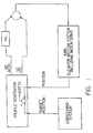
- Figure 1 is a simplified, block diagram of an exemplary embodiment of the elevator speed dictation system related to the present invention.
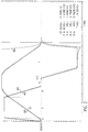
- Figure 2 is a graph of the velocity profile of the invention for an exemplary long run of an elevator car in accordance with the exemplary principles of the present invention. (It is noted that the numerical information on the lower, right side of the figure refers to the data values of the traces at the vertical cursor line located to the left side of the graphed, displayed traces; the same being true of Figs. 3-6 .)
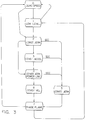
- Figure 3 is a flow chart showing the transitions between the regions of the velocity profile of Figure 2 , as well as of the velocity profiles of Figures 4-6 , with Regions 0 (zero speed) and 1 (low level phase plane) not being illustrated for simplicity purposes in the velocity profiles.
- Figure 4 is a graph of the velocity profile of the invention for an exemplary "Intermediate II" profile of the elevator car, in which the Intermediate II profile illustrates the situation wherein a transition to Region 5 occurs after a Stop Control Command (SCC).
- SCC Stop Control Command
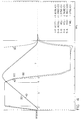
- Figure 5 is a graph of the velocity profile of the invention for an exemplary "Intermediate I" profile of the elevator car, in which the Intermediate I profile - illustrates the situation wherein there is a transition from Region 3 to Region 5 .
- Figure 6 is a graph of the velocity profile of the invention for an exemplary short run of the elevator car.
- Figure 7 is a comparative graph of exemplary velocity and acceleration curves used in the invention to find the stopping distance.
- FIG. 1 An exemplary function block diagram of the invention is shown in Figure 1 .
- the profile generator ( PROFILE GEN .) delivers a velocity signal " VD " and an acceleration signal " AD " to an elevator control system.
- the gain " KA” is used to control the blend of the acceleration signal to the velocity signal in a feed-forward control.
- the acceleration signal may be routed directly to the motor torque control point in the motor drive.
- limiters or filters are used between the VD and AD signals and the elevator motion system (" EMS ").
- the EMS includes a position reference system, which feeds back the car position (“ POSITION ”) to the profile generator.
- the function of the profile generator is to bring the car to the target position within the acceleration and jerk constraints. These constraints may be fixed or they may be a function of available power, motor torque, etc . Just before and sometimes even during a run, the constraints may be changed.
- the profile generator is designed in a structured fashion, thereby permitting adaptation to changing circumstances, even when a run is under way.
- the overall position control system should bring the car to its destination in a minimum amount of time, without vibrations or overshoot.
- the overall positioning accuracy sought is usually better than plus-or-minus three millimeters ( ⁇ 3 mm), although plus-or-minus six millimeters ( ⁇ 6 mm) is acceptable.
- the acceleration limit is usually set by the available torque in the motor drive. However, in an oversized system, passenger comfort may determine the acceleration limit.
- Part of the torque is used to offset unbalance and friction forces.
- the other part is used to accelerate or decelerate the system mass.
- Figure 2 shows the dictated and actual velocity and acceleration for an exemplary long run. Understanding this profile set is important because all other profile sets are subsets of this one. As can be seen in Figure 2 various regions 2-7 , defined and explained more fully below, are marked.
- the profiles for the first part of the run are developed on the basis of dictated acceleration. Dictated velocity is obtained by the numerical integration of the dictated acceleration. (Henceforth, as a matter of form and for simplicity purposes, dictated velocity and acceleration typically will be referred to without the adjective "dictated” being added.)
- the actual position, velocity, and acceleration are outputs from the EMS .
- Region Definition 0 zero speed 1 low level phase plane 2 constant jerk to prescribed acceleration 3 prescribed acceleration 4 constant jerk down to constant velocity 5 jerk level after generation of SCC 6 constant speed 7 phase plane Regions " 0 ,” “ 1 ,” and “ 7 " apply to runs of all lengths. Regions 0 and 1 are not shown explicitly on the profiles illustrated in Figures 2 , etc. , and the meaning of Region 1 is explained when the phase-plane Region 7 is explained.
- Region 3 The end of Region 3 is defined when "VBASE” is reached.
- VBASE can be the base velocity or speed of the motor or a lower speed.
- VBASE is subject to some variation, and, typically, it will be close to but a bit less than the base speed of the motor involved.
- a “jerk out” is then defined in Region 4 until maximum speed is reached in Region 6 . Operation continues in Region 6 , until the stop control command ( SCC) is received.
- Region 7 is then entered.
- the velocity is commanded as a function of distance-to-go on the basis of a table of velocity versus distance built up for all travel in Regions 2-5 .
- an acceleration table is also being built. Both the velocity and acceleration tables can be weighted, so that deceleration occurs in direct proportion to a set "DECELRATIO.”
- the "DECELRATIO” is usually less than one ( ⁇ 1.0), but it may also be larger than one (>1.0).
- the profile generator regions are illustrated in block form in Figure 3 .
- the transitions from Regions 1 to 0 and 0 to 1 are used at the beginning of a run for holding the elevator at the floor when the brake is lifted and the transition to Region 2 is about to commence.
- SCC Upon receipt of SCC , it is possible to leave Regions 2-4 and enter Region 5 .
- Deceleration of the elevator occurs in Region 7 using a phase-plane control.
- the dictated velocity and acceleration used are retrieved from tables built in Regions 2-5 .
- the low-level phase plane Region 1 is entered.
- the low-level-phase plane has a linear slope (velocity/DISTTG) in a range of, for example, one to four (1-4 sec -1 ) 1/second.
- Figures 4-6 Actual operation for less than full-length runs is illustrated in Figures 4-6 .
- Figure 4 is termed "Intermediate II" because the transition to Region 5 occurs after SCC .
- Figure 5 is an "Intermediate I" profile because a transition occurs from Region 3 to Region 5 .
- This figure illustrates the typical operation for a one-floor run.
- Figure 6 is a short run in which the acceleration limit, Region 3 , is not reached, and, thus, transition occurs directly from Region 2 to Region 5 .
- the timed portions of the profiles are obtained by successive numerical integrations using the trapezoidal algorithm.
- Regions 2-6 The major operations other than generation of a timed profile are listed here. Those occurring in Regions 2-6 are:
- VD For speeds where VD > LEVELVEL, the relationship between VD and DISTTG is nonlinear.
- the acceleration, velocity, and position entries in the table are obtained by successive integrations, and the table index is incremented each cycle.
- computations preferably are being made during acceleration to determine the stopping distance based on the dictation. This stopping distance is correct if no time delays exist in the velocity control system.
- the stopping distance is determined only by the current distance stored in the table. Otherwise, the stopping distance is given, after some derivation, by:
- the stopping distance must be compared not to the actual distance-to-go but to that value corrected for delays.
- the following equality defines the stop control command ( SCC ) point, when processor system delays are neglected.
- the number n 2 is usually used to account for a delay of two processor cycles.
- a linear interpolation technique preferably is used to calculate the acceleration and velocity signals from the previously constructed tables.
- the distance-to-go to the target landing is used to index the tables.
- LADTG Look-Ahead-Distance-To-Go
- LADTG as defined below is used for the proper operation of the phase plane control, especially as the target landing is approached.
- the RATIO is used to blend LADTG into DISTTG at the target landing.
- the VD n-1 * T c term is identical to that US-A-4,751,984.
- the MULTIPLIER is used to assure that LADTG matches the last distance entry stored in the phase plane tables.
- LADTG approaches the value of DISTTG.
- the rate at which the COMPENSATION term is reduced to zero is further controlled by the RATIO factor.
- RATIO As the elevator approaches the destination floor, the value of RATIO must be gradually reduced ("washed-out") from one to zero (1 to 0). Consequently, RATIO is defined as follows:
- MULTIPLIER XTBL(M) ö DISTTGT where -
- LADTGT XTBL(M)
- LADTGs are then scaled by the value of the MULTIPLIER, as shown above.
- MULTIPLIER values close to unity or one (1.0) are desirable.
- AD ⁇ A [(X - LADTG) ö (X - X1)] * (A - A1) ⁇ * MULTIPLIER
- VD V - [(X - LADTG) ö (X - X1)] * (V - V1)
- A1 ATBL(n)
- V1 VTBL(n-1)
- X1 XTBL(n-1)
- the first part of the program consists of declarative statements and comments.
- parameters for the profile are set and preliminary computations are made. This type of operation can take place adaptively in a real elevator control to adjust for changing conditions.
- Variables are initialized and flags are set. Similar operations occur in the control code used to run an elevator.
- the distance for the profile is entered.
- SCC% 1, meaning a stopping sequence should be initiated.
- the "SCC” determination is based on "DISTTG,” as computed below, “DIST.ERR,” and the dictated velocity "VD.”
- Control then shifts to the label "VELCONTROL:” .
- the subroutine "VELCONTROL” is called to simulate in simplified form the operation of the EMS of Figure 1 (a model of a DC drive may be used).
- This subroutine provides an update to the actual velocity and acceleration. Importantly, it provides the "DIST.GONE” (actual distance traveled by the elevator). From “DIST.GONE” the "DISTTG” is computed.
- the stopping sequence then commences. For other than a long run, this includes further operation with a timed profile, until a condition of zero acceleration is reached. This is analogous to operation in Region 5 , which is commented as "SCC ACTIVE".
- a region called "LOWLEV.PROFILE" is then defined.
- the simulation differs from the actual profile generator in that Region 1 here applies only to the end of the run and that the same phase-plane slope is used for table continuation and for recovery from overshoots.
Landscapes
- Engineering & Computer Science (AREA)
- Automation & Control Theory (AREA)
- Elevator Control (AREA)
Description
- The present invention relates to elevator systems and in particular to elevator velocity control. Still more precise, the present invention is related to a method for controlling the acceleration and deceleration of an elevator in an elevator speed dictation system.
- The need to control the velocity of an elevator is well known. Reference is made, for example, to US-A-4,751,984 of Walter L. Williams, Donald G. Mcpherson & Arnold Mendelsohn entitled "Dynamically Generated Adaptive Elevator Velocity Profile" issued June 21, 1988, as well as to the art cited therein.
- As noted in the document US-A-4,751,984, automatic elevator operation requires the control of elevator velocity with respect to zero or stop, at the beginning and the end of a trip, to speeds therebetween, which minimize trip time while maintaining comfort levels and other constraints. The time change in velocity for a complete trip is termed a "velocity profile." Automatic elevator control further requires control of the distance travelled during a trip in order to accomplish a precision stop at the destination floor.
- Certain velocity profile generation strategies may lead to control instabilities. A common strategy is to use a phase-plane control for precision stopping, wherein dictated velocity is a function of the distance to go to the landing. As the distance-to-go approaches zero, the slope of the velocity/distance curve approaches infinity (∞). Using linear control theory, it can be shown that the slope of the phase-plane curve represents the position error gain for phase-plane control and is proportional to position loop bandwidth. For the speed control loop to track the dictated velocity profile with stability, its bandwidth must be greater by a significant factor than the bandwidth of the position control loop.
- One strategy for reducing the required bandwidth is to limit the slope of the phase-plane velocity versus position profile (position error gain) to a maximum value, such that the position loop bandwidth is sufficiently lower than the velocity loop bandwidth.
- Generally, the torque producing capability of elevator motors may vary with speed due to motor current, voltage, and/or power limitations. If the drive is not capable of maintaining the acceleration limit under all conditions due to these torque limits, some means of reducing the acceleration (and hence torque) in the corresponding portions of the velocity profile must be provided without compromising operation of the drive at its limit or complicating the profile generation more than necessary.
- To avoid, inter alia, these problems, in document US-A-4,751,984 each segment of the velocity profile was generated at one of the limits constraining the system; viz., at maximum jerk, maximum acceleration, maximum velocity, maximum position or loop gain, or maximum motor torque. The acceleration portion of the velocity profile preferably was generated in an open loop manner, beginning with constant (maximum) jerk, transitioning to constant (maximum) acceleration after an acceleration limit is attained, and jerking out (negative jerk) at a constant rate to maximum (contract) velocity when the maximum velocity is nearly attained. However, although US-A-4,751,984 represents a very substantial advance in the art, it also was subject to improvement, to which the present invention is directed. The disclosure of the document US-A-4,751,984 is incorporated herein by reference.
- From document US-A-4,130,184 an elevator speed control system and a method implemented therein has come to be known. During the acceleration of an elevator cab, frequency modulated clock pulses are counted up by a first counter to gene-rate the command speed pattern. The second counter similarly generates second speed pattern identical in shape to and delayed a predetermined time relative to the command speed pattern. A random access memory successively stores theoretical distances of movement of the car due to the command speed pattern suitably corrected and the second speed pattern as a distance-to-speed function. When and after both patterns first equal each other, a command deceleration pattern is generated to follow objectives or the distance-to-speed function. Once the command speed again equals the objective, the intact distance-to-speed function is used as a command deceleration pattern concerning residual distances to stop floor.
- Therefore, it is an object of the present invention to produce a minimum-time velocity/acceleration profile, subject to the following constraints:
- ■ contract speed(s) (as in US-A-4,751,984);
- ■ ride comfort constraints; i.e., acceleration and jerk limits (as in US-A-4,751,984);
- ■ drive torque and power limits (following to some degree US-A-4,751,984); and
- ■ compatibility with the drive system.
- In the invention, at a speed close to the base speed of the motor, acceleration reduction preferably is used to keep power requirements well bounded without significantly compromising flight time. This is a form of acceleration profile adaptation based on speed.
- Another type of adaptation also may be used. The acceleration and jerk limits for the profile may be adjusted in accordance with available torque. The torque requirements may be determined from the load weighing signal, which gives the load in the cab. The acceleration and jerk limits for the profile can then be adjusted accordingly.
- Thus, the profile generator can be made adaptive by presetting the acceleration and jerk limits based on the load in the elevator cab. This can be done by a simple computation based on the load weight made at the beginning of a run. This could be done to permit the use of a smaller than usual drive system, if so desired.
- The dictation system of the present invention is capable of generating for output high-quality velocity and acceleration signals. It is advantageous because it is highly structured in design, tolerant of significant computational errors, and is easily modified to handle unusual situations.
- In addition, like US-A-4,751,984, the velocity-profile generation approach of the present invention preferably:
- ■ provides for precision stopping at the destination floor and re-leveling;
- ■ complies with the code required door zone and other terminal landing speed limits; and
- ■ accommodates short runs where the contract speed is not reached, as well as very short runs where the "stop control command" (SCC) is reached before the velocity "VBASE" (described more fully below) is reached.
- These objects are solved according to the invention by a method of controlling the acceleration and deceleration of an elevator in an elevator speed dictation system according to the features set out in
patent claim 1. - Dependent claims 2 to 7 exhibit further improvements of the subject-matter of
independent patent claim 1. - As part of the improvement to the approach of US-A-4,751,984, each segment of the velocity profile likewise is generated at one of the limits which constrain the system; viz., at maximum jerk, maximum acceleration, maximum velocity, maximum position or loop gain, or maximum motor torque. The acceleration portion of the velocity profile preferably is generated in an open loop manner, beginning with constant (maximum) jerk, transitioning to constant (maximum) acceleration after an acceleration limit is attained, and jerking out (negative jerk) at a constant rate to maximum (contract) velocity when the maximum velocity is nearly attained.
- The invention may be practiced in a wide variety of elevator applications utilizing known technology, in the light of the teachings of the invention, which are discussed in detail hereafter.
- Some of the technological advances achieved and/or followed in the preferred embodiment of the present invention are outlined below.
- 1. The velocity is stored in a table as a function of distance gone during acceleration. This table can be used in reverse to find dictation as a function of distance to go during deceleration. The new profile generator explicitly builds the velocity table from acceleration and jerk constraints. This means that acceleration corresponding to each velocity is known. The new profile generator stores acceleration information along with velocity information in tables having distance as the independent variable. Table entries are made during each processor cycle during acceleration. The acceleration table is used in reverse together with a numerical scaling to decelerate the elevator. Acceleration information is output by the profile generator at all times (acceleration, constant speed, deceleration). No numerical differentiation of velocity is used to find acceleration, except in special situations. This results in a high-quality acceleration signal. Also, processor time is saved.
- 2. The acceleration signal mentioned in "1" above can be blended with the velocity signal and the combination applied as dictation to a drive. This provides an "acceleration feedforward" that reduces velocity tracking time and thus makes the drive more responsive. The acceleration signal can also be applied in standard fashion to the torque input point of a drive (if available). A disadvantage of feedforward is that it makes the drive system more load sensitive. Load sensitivity can be compensated for, if a load weight signal is available. This may be accomplished by varying the proportional gain of the proportional-integral controller used in the drive as a function of load weight.
- 3. The new profile generator has a simple algorithm for computing stopping distance. The algorithm can be used for runs of all lengths. The stopping distance is computed based on the DICTATED profile.
- 4. The stopping distance in "3" is compared to DISTTG (distance to go; DRIVE OUTPUT COORDINATES) converted to DICTATION coordinates. The conversion is accomplished by subtracting the tracking distance error from DISTTG. In the new profile generator the distance error is not entered in terms of drive tracking delay and velocity. Instead, the actual, MEASURED, distance tracking error is used. The measurement is accomplished by using numerical integration of dictated velocity to find distance dictated. The


- 5. The stop control command as defined in "4" usually cannot be issued perfectly. The distance range applicable to the velocity and acceleration tables will not match the distance to go. This problem becomes especially severe when the elevator is to be decelerated with look-ahead-distance-to-go (LADTG) rather than DISTTG as the independent variable. The problem is solved in the new profile generator by the introduction of a MULTIPLIER. This multiplier is a scaling factor that acts on the LADTG to make it equal to the distance range for the velocity and acceleration tables. Usually the MULTIPLIER is a number very close to one (1.0) for long runs. It may deviate significantly from one (1.0) for very short runs because of numerical errors. The MULTIPLIER assures that numerical errors, timing delays, etc., will not cause bizarre phase plane trajectories. The phase plane-control in the profile generator is self-correcting and robust because of the MULTIPLIER.
- 6. The look-ahead-distance-to-go (LADTG) is made adaptive in the new profile generator. It is not used for runs of less than 1000 mm (pure DISTTG is used). Further, as the end of a run is approached, LADTG has a "washout" term which is a function of DISTTG. As DISTTG approaches zero, a multiplier acts on the velocity dependent portion of LADTG to make that term less and less significant. Should the control overshoot and the DISTTG go negative, phase plane control reverts to pure DISTTG, rather than LADTG as the independent variable.
- 7. The profile design is modular, structured, and deterministic. Acceleration, jerk, and distance constraints permitting, it is capable of being altered after a run has begun. The modular design makes design modifications relatively easy. Maintenance of the code and teaching of the design to new engineers is not complicated.
- 8. The profile generator can be made adaptive by presetting the acceleration and jerk limits based on the load in the elevator cab. This is done by a simple computation based on load weight made at the beginning of a run. This could be done to permit use of a smaller than usual drive system. Working of examples indicates that significant cost savings are possible with little degradation in overall service (traffic flow).
- Other features and advantages will be apparent from the specification and claims and from the accompanying drawings, which illustrate two exemplary embodiments of the invention.
- Figure 1 is a simplified, block diagram of an exemplary embodiment of the elevator speed dictation system related to the present invention.
- Figure 2 is a graph of the velocity profile of the invention for an exemplary long run of an elevator car in accordance with the exemplary principles of the present invention. (It is noted that the numerical information on the lower, right side of the figure refers to the data values of the traces at the vertical cursor line located to the left side of the graphed, displayed traces; the same being true of Figs. 3-6.)
- Figure 3 is a flow chart showing the transitions between the regions of the velocity profile of Figure 2, as well as of the velocity profiles of Figures 4-6, with Regions 0 (zero speed) and 1 (low level phase plane) not being illustrated for simplicity purposes in the velocity profiles.
- Figure 4 is a graph of the velocity profile of the invention for an exemplary "Intermediate II" profile of the elevator car, in which the Intermediate II profile illustrates the situation wherein a transition to
Region 5 occurs after a Stop Control Command (SCC). - Figure 5 is a graph of the velocity profile of the invention for an exemplary "Intermediate I" profile of the elevator car, in which the Intermediate I profile - illustrates the situation wherein there is a transition from
Region 3 toRegion 5. - Figure 6 is a graph of the velocity profile of the invention for an exemplary short run of the elevator car.
- Figure 7 is a comparative graph of exemplary velocity and acceleration curves used in the invention to find the stopping distance.
- As noted in US-A-4,751,984, in order to provide rapid, controlled and smooth motion control in an elevator, a velocity profile is generated which observes constraints regarding jerk, acceleration and equipment limitations. Typical, exemplary requirements for a high performance system are:
RISE up to 400 M LOADS 900 TO 3600 KG SPEEDS 2.5 to 10 M/S ACCEL. up to 1.5 M/S JERK up to 3.0 M/S LEVELING ±0.006 M - An exemplary function block diagram of the invention is shown in Figure 1. The profile generator (PROFILE GEN.) delivers a velocity signal "VD" and an acceleration signal "AD" to an elevator control system. The gain "KA" is used to control the blend of the acceleration signal to the velocity signal in a feed-forward control. Alternatively, the acceleration signal may be routed directly to the motor torque control point in the motor drive.
- Sometimes limiters or filters (not illustrated) are used between the VD and AD signals and the elevator motion system ("EMS"). The EMS includes a position reference system, which feeds back the car position ("POSITION") to the profile generator.
- The function of the profile generator is to bring the car to the target position within the acceleration and jerk constraints. These constraints may be fixed or they may be a function of available power, motor torque, etc. Just before and sometimes even during a run, the constraints may be changed. The profile generator is designed in a structured fashion, thereby permitting adaptation to changing circumstances, even when a run is under way.
- The overall position control system should bring the car to its destination in a minimum amount of time, without vibrations or overshoot. The overall positioning accuracy sought is usually better than plus-or-minus three millimeters (±3 mm), although plus-or-minus six millimeters (±6 mm) is acceptable.
- The acceleration limit is usually set by the available torque in the motor drive. However, in an oversized system, passenger comfort may determine the acceleration limit.
- In many systems the passenger comfort acceleration sets the acceleration with the motor torque limitation becoming a problem, only when the cab is empty or fully loaded. Most high-performance elevator systems are equipped with a load-weighing system.
- Knowledge of elevator system parameters and the load weight permits computation of the maximum allowed acceleration based on the motor torque limit. Those skilled in the elevator art may routinely make this calculation, which is based on the mass of the hoistway equipment, the overbalance used for the counterweight, the load in the cab, and the available motor torque.
- Part of the torque is used to offset unbalance and friction forces. The other part is used to accelerate or decelerate the system mass.
- The profile construction strategy of the invention will now be described first in terms of typical profiles produced by the exemplary apparatus of the invention.
- Figure 2 shows the dictated and actual velocity and acceleration for an exemplary long run. Understanding this profile set is important because all other profile sets are subsets of this one. As can be seen in Figure 2 various regions 2-7, defined and explained more fully below, are marked.
- The profiles for the first part of the run are developed on the basis of dictated acceleration. Dictated velocity is obtained by the numerical integration of the dictated acceleration. (Henceforth, as a matter of form and for simplicity purposes, dictated velocity and acceleration typically will be referred to without the adjective "dictated" being added.) The actual position, velocity, and acceleration are outputs from the EMS.
- It is noted that the

- The regions in Figure 2 are defined as follows and illustrated in block form in Figure 3:
Region Definition 0 zero speed 1 low level phase plane 2 constant jerk to prescribed acceleration 3 prescribed acceleration 4 constant jerk down to constant velocity 5 jerk level after generation of SCC 6 constant speed 7 phase plane Regions 0 and 1 are not shown explicitly on the profiles illustrated in Figures 2, etc., and the meaning ofRegion 1 is explained when the phase-plane Region 7 is explained. - In the profiles of Figure 2 and Figures 4-6, the profile traces and the parameters they represent are tabulated below:
Trace # Parameter 10 velocity 20 velocity dictation 30 acceleration 40 dictated acceleration 50 distance to go (greatly magnified) - Figure 2 will now be discussed on a time-history basis. The elevator car is stopped. It then accelerates at "constant jerk" in
Region 2 until the acceleration limit is reached. - The end of
Region 3 is defined when "VBASE" is reached. "VBASE" can be the base velocity or speed of the motor or a lower speed. "VBASE" is subject to some variation, and, typically, it will be close to but a bit less than the base speed of the motor involved. A "jerk out" is then defined inRegion 4 until maximum speed is reached inRegion 6. Operation continues inRegion 6, until the stop control command (SCC) is received. -
Region 7 is then entered. In that region the velocity is commanded as a function of distance-to-go on the basis of a table of velocity versus distance built up for all travel in Regions 2-5. At the time the velocity table is being built, an acceleration table is also being built. Both the velocity and acceleration tables can be weighted, so that deceleration occurs in direct proportion to a set "DECELRATIO." The "DECELRATIO" is usually less than one (<1.0), but it may also be larger than one (>1.0). - The profile generator regions are illustrated in block form in Figure 3. The transitions from
Regions 1 to 0 and 0 to 1 are used at the beginning of a run for holding the elevator at the floor when the brake is lifted and the transition toRegion 2 is about to commence. Upon receipt of SCC, it is possible to leave Regions 2-4 and enterRegion 5. - Deceleration of the elevator occurs in
Region 7 using a phase-plane control. The dictated velocity and acceleration used are retrieved from tables built in Regions 2-5. When the elevator has almost landed or during recovery from an overshoot, the low-levelphase plane Region 1 is entered. The low-level-phase plane has a linear slope (velocity/DISTTG) in a range of, for example, one to four (1-4 sec-1) 1/second. - Actual operation for less than full-length runs is illustrated in Figures 4-6. Figure 4 is termed "Intermediate II" because the transition to
Region 5 occurs after SCC. Figure 5 is an "Intermediate I" profile because a transition occurs fromRegion 3 toRegion 5. This figure illustrates the typical operation for a one-floor run. Figure 6 is a short run in which the acceleration limit,Region 3, is not reached, and, thus, transition occurs directly fromRegion 2 toRegion 5. - Proper operation of the profile generator system requires careful attention to detail, especially if smooth, error tolerant operation is desired. These details are described below.
- The timed portions of the profiles are obtained by successive numerical integrations using the trapezoidal algorithm. This has the following general form:

- Xn-1 is the previous value of Xn (computed at time

- T is the step size (cycle time, sampling rate).
- The major operations other than generation of a timed profile are listed here. Those occurring in Regions 2-6 are:
- 1. Build the linear portion of the phase-plane table.
- 2. Build the phase-plane table in regions 2-5.
- 3. Compute the stopping distance (
Regions - 4. Determine the distance error and SCC.
- The following operations are important in transitioning to, and operating in, Region 7 (phase plane):
- 1. Determine the "MULTIPLIER" for coordinate transformation.
- 2. Compute the Look-Ahead-Distance-To-Go ("LADTG") from DISTTG.
- 3. Interpolate the velocity and acceleration tables.
- 4. Transition to low-level phase plane at the end of the run.
- Details of the foregoing operations are discussed below.
- The phase plane table is built dynamically in a microprocessor during the timed acceleration portion of the profile. As the acceleration and velocity dictation signals are computed each cycle, they are stored in a table together with the index and a corresponding distance. The table is built to satisfy the profile requirements in the phase plane deceleration region. At low speeds where VD ≤ LEVELVEL (elevator approaches the destination), the relationship between the dictated velocity and the distance-to-go is linear -

- The corresponding dictated acceleration is calculated as -


- For speeds where VD > LEVELVEL, the relationship between VD and DISTTG is nonlinear. The acceleration, velocity, and position entries in the table are obtained by successive integrations, and the table index is incremented each cycle.
- Taking the DECELRATIO factor into account, the equations used for table building are:


- Table building continues until the acceleration reaches zero, or, in other words, it is stopped for one of two reasons:
- (1) Region 7 (phase-plane) is entered without going through Region 6 (constant velocity); or
- (2) a transition is made to
Region 6. - Besides table building, computations preferably are being made during acceleration to determine the stopping distance based on the dictation. This stopping distance is correct if no time delays exist in the velocity control system.
- The following basic equations applied to Figure 7 are used to compute the stopping distance when Region 6 (constant velocity) is not entered:

- JDn, ADn, VDn and XDn are the current dictated jerk, acceleration, velocity and distance, respectively (at time t = tn); and J0, A0, V0 and X0 are the initial jerk, acceleration, velocity and distance, respectively.
- If the SCC command is generated during the constant velocity portion (Region 6), then the stopping distance is determined only by the current distance stored in the table. Otherwise, the stopping distance is given, after some derivation, by:

- The stopping distance must be compared not to the actual distance-to-go but to that value corrected for delays. The following equality defines the stop control command (SCC) point, when processor system delays are neglected.

- The dictated distance "DIST.DICT" is computed by integrating the dictated velocity, "VDn":

- In a real system implementation, the information processing delays in the position loop become significant and must be compensated. The equality given above for "STOP.DIST" is modified as indicated for implementation in a real system:

- The number n = 2 is usually used to account for a delay of two processor cycles.
- In the phase plane region, a linear interpolation technique preferably is used to calculate the acceleration and velocity signals from the previously constructed tables. The distance-to-go to the target landing is used to index the tables.
- Table building and determination of SCC have been described to this point. The matter of transitioning to Region 7 (phase plane) will now be addressed. At the transition to
Region 7, the dictated velocities are inherently matched (AD = 0). - Distances, however, may not be matched, especially since a coordinate transformation is introduced. Distance control is shifted from distance-to-go to Look-Ahead-Distance-To-Go (LADTG). The LADTG used here is a variant of a similar quantity described in US-A-4,751,984, referred to above.
- LADTG as defined below is used for the proper operation of the phase plane control, especially as the target landing is approached. The RATIO is used to blend LADTG into DISTTG at the target landing. The VDn-1 * Tc term is identical to that US-A-4,751,984. The MULTIPLIER is used to assure that LADTG matches the last distance entry stored in the phase plane tables.


- Tc - approximates the position loop delay and is a constant, which is adjustable in the EMS.
- As the dictated velocity decreases to zero, LADTG approaches the value of DISTTG. The rate at which the COMPENSATION term is reduced to zero is further controlled by the RATIO factor.
- As the elevator approaches the destination floor, the value of RATIO must be gradually reduced ("washed-out") from one to zero (1 to 0). Consequently, RATIO is defined as follows:

- A linear definition is given here for RATIO. However, a nonlinear definition may be more useful in some circumstances. This is illustrated in the programmed simulation discussed below.
- The MULTIPLIER is calculated only once, as the profile enters the phase plane deceleration region. It then remains constant until the end of the run.

- XTBL(M) - is the last distance stored in the table, and
- DISTTGT - is the actual distance-to-go at the transition point.
- At the transition to the phase plane, LADTGT is forced to match the last phase plane entry:

- Subsequently computed LADTGs are then scaled by the value of the MULTIPLIER, as shown above.
- For best deceleration control, MULTIPLIER values close to unity or one (1.0) are desirable.
- The dictated acceleration AD and velocity VD are calculated from the phase plane table using a linear interpolation technique. LADTG is used as an indexing reference.

A = ATBL(n), V = VTBL(n), X = XTBL(n) A1 = ATBL(n-1), V1 = VTBL(n-1), and X1 = XTBL(n-1) - After the entries in the phase table are almost used up, a linear phase plane trajectory is used based on LADTG. If an overshoot occurs, similar control is used and DISTTG is used rather than LADTG. The equations applicable after leaving the phase plane table but before the target landing are:

- If the target landing is overshot, then Region 1 (low-level phase plane) is entered to bring the car back to the landing. However, the acceleration signal, if used for feed-forward control, is modified after the zero crossing. "AD" should either be set to zero or computed by the numerical (time) differentiation of VD:

- An exemplary simulation for the profile generating system written in BASIC (Microsoft's "QuickBASIC 4.0") is presented below. In the program graphics routines used with the simulation are unnecessary for this disclosure and have been removed for purposes of simplicity. The BASIC used here is structured and reads very much like ordinary English or math statements (i.e., / = divide; * = multiply; ^ = exponent; etc.). "QuickBASIC" allows simple calls to subroutines. Also, program control may be shifted by a "GO TO" to a named label.
- As can be seen, the first part of the program consists of declarative statements and comments. Next, parameters for the profile are set and preliminary computations are made. This type of operation can take place adaptively in a real elevator control to adjust for changing conditions.
- Variables are initialized and flags are set. Similar operations occur in the control code used to run an elevator.
- The distance for the profile is entered.
- The block of code called "READ PHASE PLANE TABLE" is bypassed, and control shifts to a point labeled "TIMED.PROFILE." Profile generation takes places on a region by region basis as described previously. "VD" and "AD" are found by numerical integration. Building of the phase-plane tables takes place next. There are then operations to find the dictated distance, "DIST.DICT," by numerical integration and the distance error, "DIST.ERR."
- Next, the stopping distance is found by a call to the subroutine called "STOPD." Then a check is made if SCC% = 1, meaning a stopping sequence should be initiated. The "SCC" determination is based on "DISTTG," as computed below, "DIST.ERR," and the dictated velocity "VD."
- Control then shifts to the label "VELCONTROL:" . The subroutine "VELCONTROL" is called to simulate in simplified form the operation of the EMS of Figure 1 (a model of a DC drive may be used). This subroutine provides an update to the actual velocity and acceleration. Importantly, it provides the "DIST.GONE" (actual distance traveled by the elevator). From "DIST.GONE" the "DISTTG" is computed.
- The simulation continues with a timed-based profile being generated until SCC% = 1. The stopping sequence then commences. For other than a long run, this includes further operation with a timed profile, until a condition of zero acceleration is reached. This is analogous to operation in
Region 5, which is commented as "SCC ACTIVE". - When AD = 0, control shifts to the label near the beginning of the program entitled "PP.PROFILE" - READ PHASE PLANE TABLE." The distance range for the tables is first matched to the "LADTG" (found by a call to a subroutine). The match is made using the parameter called "MULTIPLIER." The "MULTIPLIER" is computed only once during a run. Next, reading of the velocity and acceleration tables occurs, using an interpolation algorithm.
- The phase plane changes to a straight line definition when the table index N% = 1 (table exhausted). A region called "LOWLEV.PROFILE" is then defined. The simulation differs from the actual profile generator in that
Region 1 here applies only to the end of the run and that the same phase-plane slope is used for table continuation and for recovery from overshoots.


Claims (7)
- In an elevator speed dictation system, a method for controlling the acceleration and deceleration of an elevator in order to translocate the elevator from a predetermined starting location to a predetermined ending location, said method comprising the steps of:a) integrating a predetermined jerk rate to obtain a dictated acceleration value (40);b) integrating said dictated acceleration value (40) over time to obtain a dictated velocity value (20), said dictated velocity value (20) for use by the speed dictation system for causing the elevator to translocate from the predetermined starting location towards the predetermined ending location;c) integrating said dictated velocity value to obtain a dictated position value;
characterized byd) determining distance to go (50) based on the distance between the position of the elevator and the predetermined ending location;e) determining distance gone based on the distance between the position of the elevator and the starting location;f) determining distance error based on said dictated position value and said distance gone;g) determining stopping distance required to stop the elevator based on said dictated velocity value and said dictated acceleration value;h) determining compensated distance to go based on said distance to go minus said distance error minus a predetermined value based on system delays;i) repeating steps (a) through (h) over time until said stopping distance is at least equal to said compensated distance to go. - In an elevator speed dictation system, the method of claim 1 further comprising the steps of:a) determining, for each of said dictated velocity values (20); a table velocity value based on said dictated velocity value (20);b) determining, for each of said dictated velocity values (20), a table position value and a table acceleration value based on said dictated acceleration value (40); andc) storing said velocity values (10), said table position values and said table acceleration values for use by the speed dictation system for decelerating the elevator.
- In an elevator speed dictation system, the method of claim 2, wherein said step of determining a table position value comprises the steps of:a) determining a maximum velocity value corresponding to a dictated acceleration value;b) comparing said maximum velocity value to said dictated velocity value; andc) calculating said table position value corresponding to said dictated velocity value based on said comparison.
- In an elevator speed dictation system, the method of claim 2 or 3, wherein said step of determining a table acceleration value comprises the steps of:a) determining a maximum velocity value corresponding to a dictated acceleration value;b) comparing said maximum velocity value to said dictated velocity value; andc) calculating said table acceleration value corresponding to said dictated velocity value based on said comparison.
- In an elevator speed dictation system, the method of claim 2, 3, or 4, wherein the step of decelerating the elevator comprises the steps of:a) determining the distance to go to (50) the predetermined ending location when the elevator commences said deceleration;b) comparing said commence-deceleration distance to go with the most recently stored table position value;c) determining a scaling factor based on said comparison;d) reading at least a portion of said stored values of table velocity and table acceleration from the table as a function of said table position value;e) interpolating said read values of table velocity and table acceleration based on said scaling factor;f) dictating a velocity value (20) and an acceleration value (40) to the elevator based on said interpolated velocity value and said interpolated acceleration value, respectively.
- In an elevator speed dictation system, the method of claim 2, 3, or 4, wherein the step of decelerating the elevator comprises the steps of:a) determining the distance to go to (50) the predetermined ending location when the elevator commences said deceleration;b) comparing said commence-deceleration distance to go (50) with the most recently stored table position value;c) determining a multiplication factor based on said comparison;d) determining a compensation factor based on system delays and a predetermined washout factor;e) determining look-ahead distance to go based on said distance to go, said compensation factor and said multiplication factor;f) reading at least a portion of said stored values of table velocity and table acceleration from the table;g) interpolating said read values of table velocity and table acceleration based on said look-ahead distance to go;h) dictating a velocity value and an acceleration value to the elevator based on said interpolated velocity value and said interpolated acceleration value, respectively.
- In an elevator speed dictation system, the method of claim 6, wherein said washout factor is a function of distance to go (50).
Applications Claiming Priority (2)
| Application Number | Priority Date | Filing Date | Title |
|---|---|---|---|
| US07/375,429 US5035301A (en) | 1989-07-03 | 1989-07-03 | Elevator speed dictation system |
| US375429 | 1989-07-03 |
Publications (3)
| Publication Number | Publication Date |
|---|---|
| EP0406771A2 EP0406771A2 (en) | 1991-01-09 |
| EP0406771A3 EP0406771A3 (en) | 1992-06-24 |
| EP0406771B1 true EP0406771B1 (en) | 1997-02-05 |
Family
ID=23480860
Family Applications (1)
| Application Number | Title | Priority Date | Filing Date |
|---|---|---|---|
| EP90112603A Expired - Lifetime EP0406771B1 (en) | 1989-07-03 | 1990-07-02 | Elevator speed dictation system |
Country Status (8)
| Country | Link |
|---|---|
| US (1) | US5035301A (en) |
| EP (1) | EP0406771B1 (en) |
| JP (1) | JP3037970B2 (en) |
| AU (1) | AU625353B2 (en) |
| DE (1) | DE69029878T2 (en) |
| ES (1) | ES2103714T3 (en) |
| HK (1) | HK134798A (en) |
| SG (1) | SG47954A1 (en) |
Families Citing this family (28)
| Publication number | Priority date | Publication date | Assignee | Title |
|---|---|---|---|---|
| US5325036A (en) * | 1992-06-15 | 1994-06-28 | Otis Elevator Company | Elevator speed sensorless variable voltage variable frequency induction motor drive |
| IT1257416B (en) * | 1992-08-05 | 1996-01-15 | METHOD AND APPARATUS FOR THE AUTOMATIC CONTROL AND CORRECTION OF THE DECELERATION-STOP COMMAND OF THE CABIN OF AN ELEVATOR OR A LIFT WHEN VARIING THE OPERATING DATA OF THE SYSTEM. | |
| KR0186122B1 (en) * | 1995-12-01 | 1999-04-15 | 이종수 | Position control method of an elevator |
| FI101780B1 (en) * | 1996-04-30 | 1998-08-31 | Kone Corp | Lifting method and apparatus |
| KR100312768B1 (en) * | 1998-08-28 | 2002-05-09 | 장병우 | Operation speed command controlling apparatus and method for elevator |
| US6510019B1 (en) * | 1999-11-12 | 2003-01-21 | Maxtor Corporation | Acceleration tracking position controller |
| JP4158883B2 (en) | 2001-12-10 | 2008-10-01 | 三菱電機株式会社 | Elevator and its control device |
| US6619434B1 (en) * | 2002-03-28 | 2003-09-16 | Thyssen Elevator Capital Corp. | Method and apparatus for increasing the traffic handling performance of an elevator system |
| US7152083B2 (en) * | 2002-09-11 | 2006-12-19 | The Research Foundation Of State University Of New York | Jerk limited time delay filter |
| FI118640B (en) * | 2004-09-27 | 2008-01-31 | Kone Corp | Condition monitoring method and system for measuring the lifting platform stopping accuracy |
| JP2008516867A (en) * | 2004-10-14 | 2008-05-22 | オーチス エレベータ カンパニー | Elevating motion profile control to reduce power consumption |
| WO2006046295A1 (en) * | 2004-10-28 | 2006-05-04 | Mitsubishi Denki Kabushiki Kaisha | Control device for rotating machine for elevator |
| FI119878B (en) * | 2005-02-04 | 2009-04-30 | Kone Corp | A system and method for improving elevator safety |
| WO2007039925A1 (en) * | 2005-09-30 | 2007-04-12 | Mitsubishi Denki Kabushiki Kaisha | Device for controlling elevator operation |
| KR101229023B1 (en) * | 2008-03-17 | 2013-02-01 | 오티스 엘리베이터 컴파니 | Elevator dispatching control for sway mitigation |
| US8490753B2 (en) * | 2008-06-13 | 2013-07-23 | Mitsubishi Electric Corporation | Elevator control apparatus with speed control to alleviate passenger ear block discomfort |
| GB2476590B (en) * | 2008-08-04 | 2013-01-09 | Otis Elevator Co | Elevator motion profile control |
| FR2937432B1 (en) * | 2008-10-22 | 2015-10-30 | Schneider Toshiba Inverter | METHOD AND DEVICE FOR CONTROLLING A LIFTING LOAD |
| CN102256887B (en) * | 2008-12-17 | 2014-03-05 | 奥的斯电梯公司 | Elevator braking control |
| FI121879B (en) * | 2010-04-16 | 2011-05-31 | Kone Corp | Lift system |
| FI20105587A0 (en) | 2010-05-25 | 2010-05-25 | Kone Corp | A method for limiting the load on an elevator assembly and an elevator assembly |
| US9809418B2 (en) | 2016-02-29 | 2017-11-07 | Otis Elevator Company | Advanced smooth rescue operation |
| US9776640B1 (en) | 2016-03-30 | 2017-10-03 | Linestream Technologies | Automatic determination of maximum acceleration for motion profiles |
| CN106707022A (en) * | 2017-01-23 | 2017-05-24 | 无锡英威腾电梯控制技术有限公司 | Method for acquiring running parameters of elevator and sampler |
| US11548758B2 (en) * | 2017-06-30 | 2023-01-10 | Otis Elevator Company | Health monitoring systems and methods for elevator systems |
| US11584614B2 (en) | 2018-06-15 | 2023-02-21 | Otis Elevator Company | Elevator sensor system floor mapping |
| CN115159289B (en) * | 2022-07-13 | 2023-12-08 | 北京云迹科技股份有限公司 | Elevator interaction method, device, electronic equipment and medium |
| EP4369116A1 (en) * | 2022-11-08 | 2024-05-15 | B&R Industrial Automation GmbH | Method for standstill control of a multi-body system |
Family Cites Families (5)
| Publication number | Priority date | Publication date | Assignee | Title |
|---|---|---|---|---|
| US3783974A (en) * | 1972-05-09 | 1974-01-08 | Reliance Electric Co | Predictive drive control |
| JPS598622B2 (en) * | 1976-05-27 | 1984-02-25 | 三菱電機株式会社 | Elevator speed control device |
| JPH0655037B2 (en) * | 1983-07-15 | 1994-07-20 | シャープ株式会社 | Servo motor speed control method |
| US4751984A (en) * | 1985-05-03 | 1988-06-21 | Otis Elevator Company | Dynamically generated adaptive elevator velocity profile |
| US4738337A (en) * | 1987-07-29 | 1988-04-19 | Westinghouse Electric Corp. | Method and apparatus for providing a load compensation signal for a traction elevator system |
-
1989
- 1989-07-03 US US07/375,429 patent/US5035301A/en not_active Expired - Fee Related
-
1990
- 1990-07-02 ES ES90112603T patent/ES2103714T3/en not_active Expired - Lifetime
- 1990-07-02 EP EP90112603A patent/EP0406771B1/en not_active Expired - Lifetime
- 1990-07-02 AU AU58673/90A patent/AU625353B2/en not_active Ceased
- 1990-07-02 SG SG1996005623A patent/SG47954A1/en unknown
- 1990-07-02 DE DE69029878T patent/DE69029878T2/en not_active Expired - Fee Related
- 1990-07-03 JP JP2176108A patent/JP3037970B2/en not_active Expired - Lifetime
-
1997
- 1997-06-26 HK HK134797A patent/HK134798A/en unknown
Also Published As
| Publication number | Publication date |
|---|---|
| JP3037970B2 (en) | 2000-05-08 |
| DE69029878D1 (en) | 1997-03-20 |
| EP0406771A2 (en) | 1991-01-09 |
| SG47954A1 (en) | 1998-04-17 |
| EP0406771A3 (en) | 1992-06-24 |
| JPH03143883A (en) | 1991-06-19 |
| US5035301A (en) | 1991-07-30 |
| DE69029878T2 (en) | 1997-05-22 |
| AU625353B2 (en) | 1992-07-09 |
| HK134798A (en) | 1998-02-27 |
| ES2103714T3 (en) | 1997-10-01 |
| AU5867390A (en) | 1991-01-03 |
Similar Documents
| Publication | Publication Date | Title |
|---|---|---|
| EP0406771B1 (en) | Elevator speed dictation system | |
| US4751984A (en) | Dynamically generated adaptive elevator velocity profile | |
| JPS6319428B2 (en) | ||
| US5073748A (en) | Method for limiting the rate-of-change of acceleration in numerical driving systems | |
| US5747755A (en) | Elevator position compensation system | |
| EP0074093B1 (en) | Controller for elevator | |
| US5070287A (en) | Method for a numerical positioning control system | |
| US4220221A (en) | Method and apparatus for producing a speed pattern for an elevator car or similar vehicle | |
| EP0382939B1 (en) | Hydraulic elevator system | |
| JPH0122198B2 (en) | ||
| JP2645464B2 (en) | Adjustment method of elevator position control device | |
| CA1201832A (en) | Speed pattern generator for elevator car | |
| WO1992018411A1 (en) | Method of controlling a plurality of elevators moving in a common hoistway | |
| HK134797A (en) | Elevator speed dictation system | |
| JP2002370418A (en) | Method of controlling print head motor and printer | |
| JPH07121227A (en) | Asymmetrical acceleration and deceleration filter | |
| KR100186381B1 (en) | Synchronous position control method of elevator | |
| JPH0783526B2 (en) | Automatic vehicle driving method | |
| JPH0680326A (en) | Elevator control device | |
| JPH0991005A (en) | Orbit controller | |
| JP2833440B2 (en) | Moving speed control device | |
| CA1115865A (en) | Method and apparatus for producing a speed pattern for an elevator car or similar vehicle | |
| SU826282A1 (en) | Programme-control device | |
| JPH02137006A (en) | speed control device | |
| JPS58214905A (en) | Servo system feed forward signal generation method |
Legal Events
| Date | Code | Title | Description |
|---|---|---|---|
| PUAI | Public reference made under article 153(3) epc to a published international application that has entered the european phase |
Free format text: ORIGINAL CODE: 0009012 |
|
| AK | Designated contracting states |
Kind code of ref document: A2 Designated state(s): CH DE ES FR GB IT LI |
|
| PUAL | Search report despatched |
Free format text: ORIGINAL CODE: 0009013 |
|
| AK | Designated contracting states |
Kind code of ref document: A3 Designated state(s): CH DE ES FR GB IT LI |
|
| 17P | Request for examination filed |
Effective date: 19921209 |
|
| 17Q | First examination report despatched |
Effective date: 19940303 |
|
| GRAG | Despatch of communication of intention to grant |
Free format text: ORIGINAL CODE: EPIDOS AGRA |
|
| GRAH | Despatch of communication of intention to grant a patent |
Free format text: ORIGINAL CODE: EPIDOS IGRA |
|
| GRAH | Despatch of communication of intention to grant a patent |
Free format text: ORIGINAL CODE: EPIDOS IGRA |
|
| GRAA | (expected) grant |
Free format text: ORIGINAL CODE: 0009210 |
|
| AK | Designated contracting states |
Kind code of ref document: B1 Designated state(s): CH DE ES FR GB IT LI |
|
| ITF | It: translation for a ep patent filed | ||
| REG | Reference to a national code |
Ref country code: CH Ref legal event code: NV Representative=s name: E. BLUM & CO. PATENTANWAELTE Ref country code: CH Ref legal event code: EP |
|
| ET | Fr: translation filed | ||
| REF | Corresponds to: |
Ref document number: 69029878 Country of ref document: DE Date of ref document: 19970320 |
|
| PGFP | Annual fee paid to national office [announced via postgrant information from national office to epo] |
Ref country code: FR Payment date: 19970613 Year of fee payment: 8 |
|
| PGFP | Annual fee paid to national office [announced via postgrant information from national office to epo] |
Ref country code: GB Payment date: 19970620 Year of fee payment: 8 |
|
| PGFP | Annual fee paid to national office [announced via postgrant information from national office to epo] |
Ref country code: DE Payment date: 19970623 Year of fee payment: 8 |
|
| PGFP | Annual fee paid to national office [announced via postgrant information from national office to epo] |
Ref country code: CH Payment date: 19970630 Year of fee payment: 8 |
|
| PGFP | Annual fee paid to national office [announced via postgrant information from national office to epo] |
Ref country code: ES Payment date: 19970715 Year of fee payment: 8 |
|
| REG | Reference to a national code |
Ref country code: ES Ref legal event code: FG2A Ref document number: 2103714 Country of ref document: ES Kind code of ref document: T3 |
|
| PLBE | No opposition filed within time limit |
Free format text: ORIGINAL CODE: 0009261 |
|
| STAA | Information on the status of an ep patent application or granted ep patent |
Free format text: STATUS: NO OPPOSITION FILED WITHIN TIME LIMIT |
|
| 26N | No opposition filed | ||
| PG25 | Lapsed in a contracting state [announced via postgrant information from national office to epo] |
Ref country code: GB Free format text: LAPSE BECAUSE OF NON-PAYMENT OF DUE FEES Effective date: 19980702 |
|
| PG25 | Lapsed in a contracting state [announced via postgrant information from national office to epo] |
Ref country code: ES Free format text: LAPSE BECAUSE OF THE APPLICANT RENOUNCES Effective date: 19980703 |
|
| PG25 | Lapsed in a contracting state [announced via postgrant information from national office to epo] |
Ref country code: LI Free format text: LAPSE BECAUSE OF NON-PAYMENT OF DUE FEES Effective date: 19980731 Ref country code: CH Free format text: LAPSE BECAUSE OF NON-PAYMENT OF DUE FEES Effective date: 19980731 |
|
| GBPC | Gb: european patent ceased through non-payment of renewal fee |
Effective date: 19980702 |
|
| REG | Reference to a national code |
Ref country code: CH Ref legal event code: PL |
|
| PG25 | Lapsed in a contracting state [announced via postgrant information from national office to epo] |
Ref country code: FR Free format text: LAPSE BECAUSE OF NON-PAYMENT OF DUE FEES Effective date: 19990331 |
|
| PG25 | Lapsed in a contracting state [announced via postgrant information from national office to epo] |
Ref country code: DE Free format text: LAPSE BECAUSE OF NON-PAYMENT OF DUE FEES Effective date: 19990501 |
|
| REG | Reference to a national code |
Ref country code: FR Ref legal event code: ST |
|
| REG | Reference to a national code |
Ref country code: ES Ref legal event code: FD2A Effective date: 20001102 |
|
| PG25 | Lapsed in a contracting state [announced via postgrant information from national office to epo] |
Ref country code: IT Free format text: LAPSE BECAUSE OF NON-PAYMENT OF DUE FEES;WARNING: LAPSES OF ITALIAN PATENTS WITH EFFECTIVE DATE BEFORE 2007 MAY HAVE OCCURRED AT ANY TIME BEFORE 2007. THE CORRECT EFFECTIVE DATE MAY BE DIFFERENT FROM THE ONE RECORDED. Effective date: 20050702 |