US11548758B2 - Health monitoring systems and methods for elevator systems - Google Patents
Health monitoring systems and methods for elevator systems Download PDFInfo
- Publication number
- US11548758B2 US11548758B2 US16/000,004 US201816000004A US11548758B2 US 11548758 B2 US11548758 B2 US 11548758B2 US 201816000004 A US201816000004 A US 201816000004A US 11548758 B2 US11548758 B2 US 11548758B2
- Authority
- US
- United States
- Prior art keywords
- motion state
- elevator
- state sensor
- elevator car
- car
- Prior art date
- Legal status (The legal status is an assumption and is not a legal conclusion. Google has not performed a legal analysis and makes no representation as to the accuracy of the status listed.)
- Active, expires
Links
Images


Classifications
-
- B—PERFORMING OPERATIONS; TRANSPORTING
- B66—HOISTING; LIFTING; HAULING
- B66B—ELEVATORS; ESCALATORS OR MOVING WALKWAYS
- B66B5/00—Applications of checking, fault-correcting, or safety devices in elevators
- B66B5/0006—Monitoring devices or performance analysers
-
- B—PERFORMING OPERATIONS; TRANSPORTING
- B66—HOISTING; LIFTING; HAULING
- B66B—ELEVATORS; ESCALATORS OR MOVING WALKWAYS
- B66B1/00—Control systems of elevators in general
- B66B1/24—Control systems with regulation, i.e. with retroactive action, for influencing travelling speed, acceleration, or deceleration
- B66B1/28—Control systems with regulation, i.e. with retroactive action, for influencing travelling speed, acceleration, or deceleration electrical
- B66B1/30—Control systems with regulation, i.e. with retroactive action, for influencing travelling speed, acceleration, or deceleration electrical effective on driving gear, e.g. acting on power electronics, on inverter or rectifier controlled motor
-
- B—PERFORMING OPERATIONS; TRANSPORTING
- B66—HOISTING; LIFTING; HAULING
- B66B—ELEVATORS; ESCALATORS OR MOVING WALKWAYS
- B66B1/00—Control systems of elevators in general
- B66B1/02—Control systems without regulation, i.e. without retroactive action
- B66B1/06—Control systems without regulation, i.e. without retroactive action electric
-
- B—PERFORMING OPERATIONS; TRANSPORTING
- B66—HOISTING; LIFTING; HAULING
- B66B—ELEVATORS; ESCALATORS OR MOVING WALKWAYS
- B66B5/00—Applications of checking, fault-correcting, or safety devices in elevators
- B66B5/0006—Monitoring devices or performance analysers
- B66B5/0018—Devices monitoring the operating condition of the elevator system
-
- B—PERFORMING OPERATIONS; TRANSPORTING
- B66—HOISTING; LIFTING; HAULING
- B66B—ELEVATORS; ESCALATORS OR MOVING WALKWAYS
- B66B7/00—Other common features of elevators
- B66B7/02—Guideways; Guides
-
- B—PERFORMING OPERATIONS; TRANSPORTING
- B66—HOISTING; LIFTING; HAULING
- B66B—ELEVATORS; ESCALATORS OR MOVING WALKWAYS
- B66B2201/00—Aspects of control systems of elevators
Definitions
- the subject matter disclosed herein generally relates to elevator systems and, more particularly, to health monitoring systems and methods of features of elevator systems.
- An elevator system typically includes a plurality of belts or ropes (load bearing members) that move an elevator car vertically within a hoistway or elevator shaft between a plurality of elevator landings.
- changes in magnitude of a load within the car can cause changes in vertical motion state (e.g., position, velocity, acceleration) of the car relative to the landing.
- the elevator car can move vertically down relative to the elevator landing, for example, when one or more passengers and/or cargo move from the landing into the elevator car.
- the elevator car can move vertically up relative to the elevator landing when one or more passengers and/or cargo move from the elevator car onto the landing.
- Such changes in the vertical position of the elevator car can be caused by soft hitch springs and/or stretching and/or contracting of the load bearing members, particularly where the elevator system has a relatively large travel height and/or a relatively small number of load bearing members.
- the stretching and/or contracting of the load bearing members and/or hitch springs can create disruptive oscillations in the vertical position of the elevator car, e.g., an up and down “bounce” motion.
- methods of monitoring dynamic compensation control systems of elevator systems include monitoring a first motion state sensor signal generated by a first motion state sensor, the first motion state sensor associated with an elevator machine, monitoring a second motion state sensor signal generated by a second motion state sensor, the second motion state sensor located on an elevator car, determining an operational status of the second motion state sensor based on an analysis of the first motion state sensor signal and the second motion state sensor signal, and when it is determined that a failure status of the second motion state sensor is present, the method further comprises deactivating a dynamic compensation control mode of operation of the elevator system.
- further embodiments of the methods may include performing a dynamic compensation control mode of operation to control a motion state of the elevator car relative to a landing with a computing system and the elevator machine, wherein the dynamic compensation control includes receiving the first motion state sensor signal at a computing system, receiving the second motion state sensor signal at the computing system, and controlling the elevator machine to minimize oscillations, vibrations, excessive position deflections, and/or bounce of the elevator car at the landing.
- further embodiments of the methods may include that the determination of the operational status of the second motion state sensor is performed during a travel of the elevator car between landings of the elevator system.
- further embodiments of the methods may include performing a re-leveling operation with the elevator machine and the first motion state sensor signal at a landing when the dynamic compensation control mode of operation is deactivated.
- further embodiments of the methods may include that the failure status is based on a determination that the second motion state sensor signal is outside of a predetermined tolerance.
- further embodiments of the methods may include that the predetermined tolerance is defined by an upper boundary and a lower boundary relative to the first motion state sensor signal.
- further embodiments of the methods may include that the predetermined tolerance is one of (i) fixed for all distances of travel of the elevator car with an elevator shaft or (ii) variable based on a distance of travel of the elevator car within an elevator shaft.
- further embodiments of the methods may include that the first motion state sensor and the second motion state sensor each measure one of a position, a velocity, an acceleration, or a combination thereof.
- further embodiments of the methods may include generating a notification regarding a failure status and transmitting said notification to provide notice that maintenance is required on the second motion state sensor.
- elevator control systems include an elevator machine operably connected to an elevator car located within an elevator shaft, a first motion state sensor arranged relative to the elevator machine to monitor a motion state of the elevator car within the elevator shaft, a second motion state sensor arranged on the elevator car and configured to monitor a motion state of the elevator car with the elevator shaft, and a computing system in communication with the first motion state sensor and the second motion state sensor, the computing system receiving a respective first motion state sensor signal and a second motion state sensor signal, the computing system configured to perform health monitoring of the second motion state sensor.
- the health monitoring includes monitoring the first and second motion state sensor signals, determining an operational status of the second motion state sensor based on an analysis of the first motion state sensor signal and the second motion state sensor signal, and, when it is determined that a failure status of the second motion state sensor is present, the computing system deactivates a dynamic compensation control mode of operation of the elevator system.
- further embodiments of the elevator control systems may include that the computing system is configured to perform a dynamic compensation control mode of operation to control a motion state of the elevator car relative to a landing by controlling the elevator machine.
- the dynamic compensation control includes receiving the first and second motion state sensor signals at the computing system and controlling the elevator machine to minimize oscillations, vibrations, excessive position deflections, and/or bounce of the elevator car at the landing.
- further embodiments of the elevator control systems may include that the determination of the operational status of the second motion state sensor is performed during a travel of the elevator car between landings of the elevator system.
- further embodiments of the elevator control systems may include that the computing system is configured to perform a re-leveling operation with the elevator machine and the first motion state sensor signal at a landing when the dynamic compensation control mode of operation is deactivated.
- further embodiments of the elevator control systems may include that the failure status is based on a determination that the second motion state sensor signal is outside of a predetermined tolerance.
- further embodiments of the elevator control systems may include that the predetermined tolerance is defined by an upper boundary and a lower boundary relative to the first motion state sensor signal.
- further embodiments of the elevator control systems may include that the predetermined tolerance is one of (i) fixed for all distances of travel of the elevator car with an elevator shaft or (ii) variable based on a distance of travel of the elevator car within an elevator shaft.
- further embodiments of the elevator control systems may include that the motion states monitored by the first and second motion states sensors are one of a position, a velocity, an acceleration, or a combination thereof.
- further embodiments of the elevator control systems may include that the computing system is configured to generate a notification regarding a failure status and transmitting said notification to provide notice that maintenance is required on the second motion state sensor.
- further embodiments of the elevator control systems may include that at least one of the first motion state sensor and the second motion state sensor is an encoder.
- further embodiments of the elevator control systems may include a roller guide located on an exterior of the elevator car and arranged to guide movement of the elevator car relative to a guide rail, wherein the second motion state sensor is an encoder arranged to monitor the roller guide.
- FIG. 1 A is a schematic illustration of an elevator system that may employ various embodiments of the disclosure
- FIG. 1 B is a side schematic illustration of an elevator car of FIG. 1 A attached to a guide rail track;
- FIG. 2 A is a partial isometric illustration of an elevator car frame having roller guides in accordance with an embodiment of the present disclosure mounted thereto;
- FIG. 2 B is a plan view schematic illustration of one of the roller guides of FIG. 2 A ;
- FIG. 3 is a schematic block diagram illustrating a computing system that may be configured for one or more embodiments of the present disclosure
- FIG. 4 is a schematic block diagram illustrating a health monitoring system in accordance with an embodiment of the present disclosure
- FIG. 5 A is a schematic plot of an elevator system operating in a normal condition, showing first and second motion state sensor signals
- FIG. 5 B is a schematic plot of an elevator system with a second motion state sensor operating in a failure state
- FIG. 6 is a schematic illustration of a plot to demonstrate a health monitoring process in accordance with an embodiment of the present disclosure
- FIG. 7 is a schematic illustration of a plot to demonstrate another health monitoring process in accordance with an embodiment of the present disclosure.
- FIG. 8 is a flow process for controlling an elevator system in accordance with an embodiment of the present disclosure.
- FIG. 1 A is a perspective view of an elevator system 101 including an elevator car 103 , a counterweight 105 , a roping 107 , a guide rail 109 , a machine 111 , a machine motion state sensor 113 , and a controller 115 .
- the elevator car 103 and counterweight 105 are connected to each other by the roping 107 .
- the roping 107 may include or be configured as, for example, ropes, steel cables, and/or coated-steel belts.
- the counterweight 105 is configured to balance a load of the elevator car 103 and is configured to facilitate movement of the elevator car 103 concurrently and in an opposite direction with respect to the counterweight 105 within an elevator shaft 117 and along the guide rail 109 .
- the roping 107 engages the machine 111 , which is part of an overhead structure of the elevator system 101 .
- the machine 111 is configured to control movement between the elevator car 103 and the counterweight 105 .
- the machine motion state sensor 113 may be mounted on an upper sheave of a speed-governor system 119 and may be configured to provide motion state signals related to a motion state of the elevator car 103 within the elevator shaft 117 .
- the term “motion state” includes various properties of motion including, but not limited to, position, velocity, acceleration, and combinations thereof.
- the machine motion state sensor 113 may be directly mounted to a moving component of the machine 111 , or may be located in other positions and/or configurations as known in the art.
- the machine motion state sensor 113 may be an encoder connected to the machine 111 .
- the controller 115 is located, as shown, in a controller room 121 of the elevator shaft 117 and is configured to control the operation of the elevator system 101 , and particularly the elevator car 103 .
- the controller 115 may provide drive signals to the machine 111 to control the acceleration, deceleration, leveling, stopping, etc. of the elevator car 103 .
- the controller 115 may also be configured to receive motion state signals from the machine motion state sensor 113 .
- the elevator car 103 may stop at one or more landings 125 as controlled by the controller 115 .
- the controller 115 can be located and/or configured in other locations or positions within the elevator system 101 .
- the machine 111 may include a motor or similar driving mechanism.
- the machine 111 is configured to include an electrically driven motor.
- the power supply for the motor may be any power source, including a power grid, which, in combination with other components, is supplied to the motor.
- FIG. 1 A is merely a non-limiting example presented for illustrative and explanatory purposes.
- FIG. 1 B is a side view schematic illustration of the elevator car 103 as operably connected to the guide rail 109 .
- the elevator car 103 connects to the guide rail 109 by one or more guiding devices 127 .
- the guiding devices 127 may be guide shoes, rollers, etc., as will be appreciated by those of skill in the art.
- the guide rail 109 defines a guide rail track that has a base 129 and a blade 131 extending therefrom.
- the guiding devices 127 of the elevator car 103 are configured to run along and/or engage with the blade 131 of the guide rail 109 .
- the guide rail 109 mounts to a wall 133 of the elevator shaft 117 (shown in FIG. 1 A ) by one or more brackets 135 .
- the brackets 135 are configured to fixedly mount to the wall 133 , such as by bolts, fasteners, etc. as known in the art.
- the base 129 of the guide rail 109 fixedly attaches to the brackets 135 , and thus the guide rail 109 can be fixedly and securely mounted to the wall 133 .
- a guide rail of a counterweight of an elevator system may be similarly configured.
- Embodiments provided herein are directed to apparatuses, systems, and methods related to elevator control and, particularly, to management systems for vibration compensation systems that rapidly adjust and account for bounce, oscillations, and/or vibrations of elevator cars.
- an “elevator dynamic compensation control mode” is a mode of operation that is used by elevator systems at landings when an elevator car moves up or down (e.g., bounce) due to load changes and/or extension/contraction of load bearing members to provide a continuous re-levelling feature (e.g., level user experience for passengers).
- systems and methods of monitoring such elevator dynamic compensation control systems are provided.
- An elevator dynamic compensation control system in accordance with embodiments of the present disclosure has two motion state sensors.
- a first motion state sensor of the elevator dynamic compensation control system may be the machine motion state sensor (e.g., machine motion state sensor 113 shown in FIG. 1 A ) that is used for motion control of the elevator car.
- a second motion state sensor may be installed on the elevator car itself (e.g., an “on-car motion state sensor”), as described herein, that is used to control elevator car sag and bounce.
- the second motion state sensor in some embodiments, may be an on-car encoder.
- a health management system in accordance with embodiments of the present disclosure, is in communication with the first and second motion state sensors and receives motion state sensor signals from the motion state sensors to estimate a performance of the on-car motion state sensor to ensure proper installation and adjustment and to minimize a likelihood of failure during operation.
- a comparison of the motion state sensor signals can be constantly performed in a diagnostic and prognostic manner to detect and predict failure or other health status of the elevator dynamic compensation control system and on-car motion state sensor.
- a motion state detection element and/or functionality is provided on-car, and can be integrated into roller guides of the elevator car (e.g., guiding devices 127 shown in FIG. 1 B ). That is, in accordance with embodiments of the present disclosure, a motion state sensing element (e.g., an on-car motion state sensor) is incorporated into the guiding device such that an accurate motion state of the elevator car within the elevator shaft can be determined.
- a motion state sensing element e.g., an on-car motion state sensor
- the term “motion state” includes, but is not limited to, position, velocity, and acceleration of an elevator car.
- the motion state information can then be used to minimize vibration, oscillation, and bounce of the elevator car.
- the motion state information can be provided to a health monitoring system to ensure proper operation of the on-car motion state sensor.
- FIGS. 2 A- 2 B schematic illustrations of elevator car guiding devices in accordance with a non-limiting embodiment of the present disclosure are shown.
- FIG. 2 A is a partial isometric illustration of an elevator car frame 200 having two elevator car guiding devices 202 installed thereon.
- FIG. 2 B is a top-down schematic illustration of an elevator car guiding device 202 as engaged within a guide rail 204 of an elevator system.
- the elevator car frame 200 includes a crosshead frame 206 extending between vertical stiles 208 .
- the elevator car guiding devices 202 are mounted to at least one of the crosshead from 206 and the vertical stiles 208 , as known in the art, at a mounting base 210 .
- the mounting base 210 defines at least part of a roller guide frame that is used to mount and support rolling components to an elevator car.
- the elevator car guiding devices 202 are each configured to engage with and move along a guide rail 212 (shown in FIG. 2 B ).
- the guide rail 212 has a base 214 and a blade 216 and the elevator car guiding devices 202 engage with and move along the blade 216 of the guide rail 212 .
- the elevator car guiding device 202 shown in FIG. 2 B includes a first roller 218 and two second rollers 220 .
- the first roller 218 is a side-to-side roller and the second rollers 220 are front-to-back rollers.
- FIGS. 2 A- 2 B those of skill in the art will appreciate that embodiments provided herein are applicable to various other elevator car guiding device configurations/arrangements.
- Each of the first and second rollers 218 , 220 include roller wheels as known in the art.
- rollers 218 , 220 are movably or rotatably mounted to the mounting base 210 by a first support bracket 222 and second support brackets 224 , respectively.
- roller guides typically utilize wheels with rolling element bearings mounted on stationary pins (spindles) fixed to pivoting arms supported by the roller guides base, which in turn interfaces with the car frame, as described above.
- the pivoting arm is retained by a stationary pivot pin fixed to the base.
- a spring is configured to provide a restoring force and a displacement stop (e.g., a bumper).
- the roller wheels contact the guide rails of the elevator system and spin with the vertical motion of the car.
- embodiments of the present disclosure replaces one pivoting arm with an arm that supports a spinning shaft fixed to the roller wheel.
- the spinning shaft extends thru the arm to allow interface with an on-car motion state sensor secured to the pivoting arm with a radially compliant mount.
- the first support bracket 222 also supports a motion state sensing assembly 226 .
- the motion state sensing assembly 226 includes an on-car motion state sensor 228 and a connecting element 230 , as described herein.
- the motion state sensing assembly 226 is configured to determine a motion state of an elevator car within an elevator shaft.
- the motion state sensing assembly 226 in some embodiments such as that shown in FIGS. 2 A- 2 B , includes an on-car motion state sensor 228 , such as an on-car motion state sensor.
- the on-car motion state sensor 228 in some configurations, can be a rotary motion state sensor or shaft motion state sensor that is an electro-mechanical device that converts the angular position or motion of a shaft or axle (e.g., connecting element 230 ) to an analog or digital code or signal.
- the signal produced by the on-car motion state sensor 228 can be transmitted to an elevator machine and/or controller to determine a specific position of the on-car motion state sensor 228 within the elevator shaft, and thus a motion state of the elevator car to which the on-car motion state sensor 228 is attached can be obtained.
- the motion state sensing assembly 226 can include various electrical components, such as memory, processor(s), and communication components (e.g., wired and/or wireless communication controllers) to determine a motion state and transmit such information to a controller or elevator machine such that the controller or elevator machine can determine an accurate motion state of the elevator car. With such information, the controller or elevator machine can perform improved control, such as, for example, during dynamic compensation control modes of operation and/or to prevent vibrations, oscillations, and/or bounce of the elevator car.
- the computing system 300 may be configured as part of and/or in communication with an elevator controller, e.g., controller 115 shown in FIG. 1 , as part of a dynamic compensation control mode system, or a discrete elevator health monitoring system.
- the computing system 300 includes a memory 302 which can store executable instructions and/or data associated with health monitoring processes.
- the executable instructions can be stored or organized in any manner and at any level of abstraction, such as in connection with one or more applications, processes, routines, procedures, methods, etc.
- at least a portion of the instructions stored on memory 302 are associated with a health monitoring program 304 .
- the memory 302 may store data 306 .
- the data 306 may include, but is not limited to, elevator car data, elevator modes of operation, commands, or any other type(s) of data as will be appreciated by those of skill in the art.
- the instructions stored in the memory 302 may be executed by one or more processors, such as a processor 308 .
- the processor 308 may be operative on the data 306 .
- the processor 308 is coupled to one or more input/output (I/O) devices 310 .
- the I/O device(s) 310 may include one or more of a keyboard or keypad, a touchscreen or touch panel, a display screen, a microphone, a speaker, a mouse, a button, a remote control, a joystick, a printer, a telephone or mobile device (e.g., a smartphone), a sensor, etc.
- the I/O device(s) 310 in some embodiments, include communication components, such as broadband or wireless communication elements.
- the I/O device(s) 310 can be remote from the other components of the computing system 300 , such as through a remote access terminal or internet connected devices.
- the components of the computing system 300 may be operably and/or communicably connected by one or more buses.
- the computing system 300 may further include other features or components as known in the art.
- the computing system 300 may include one or more transceivers and/or devices configured to transmit and/or receive information or data from sources external to the computing system 300 (e.g., part of the I/O devices 310 ) and/or with motion state sensors associated with health monitoring, as described herein (e.g., machine motion state sensor 113 and on-car motion state sensor 228 , described above).
- the computing system 300 may be configured to receive information over a network (wired or wireless) or through a cable or wireless connection with one or more devices remote from the computing system 300 (e.g.
- the information received over the communication network can be stored in the memory 302 (e.g., as data 306 ) and/or may be processed and/or employed by one or more programs or applications (e.g., program 304 ) and/or the processor 308 .
- the computing system 300 is one example of a computing system that can be used to execute and/or perform embodiments and/or processes described herein.
- the computing system 300 when configured as part of an elevator control system, is used to receive commands and/or instructions and is configured to control operation of an elevator car through control of an elevator machine.
- the computing system 300 can be integrated into or separate from (but in communication therewith) an elevator controller and/or elevator machine and operate as a portion of a dynamic compensation control system and/or health monitoring system.
- the term “dynamic compensation control system” refers to one or more components configured to control movement and, particularly, a dynamic compensation control mode of an elevator car.
- the computing system 300 is configured to operate and/or perform a health monitoring operation with respect to an elevator dynamic compensation control system.
- a dynamic compensation control mode of operation is used to mitigate or significantly reduce elevator car bounce.
- elevator car bounce may be a result of long load bearing members (e.g., belts, ropes, cables, or other suspension mechanism) used to suspend and move the elevator car within an elevator shaft and/or as a result of changes in elevator car load (e.g., changes in weight pulling on the load bearing members).
- long load bearing members e.g., belts, ropes, cables, or other suspension mechanism
- changes in elevator car load e.g., changes in weight pulling on the load bearing members.
- a suspended elevator car may bounce or move slightly when at a landing.
- Such effects may be observed in high rise elevator systems (e.g., systems within tall buildings) when the elevator car is at a relatively low landing (e.g., close to the ground floor of the building).
- the load bearing members can be sufficiently extended and long that extension (e.g., stretching) or contraction of the load bearing members may occur.
- extension or contraction can cause the elevator car to move relative to a stopped position, even if brakes are engaged to prevent movement of the machine. That is, the movement of the elevator car can be independent of the operation of the machine that drives movement of the elevator car within the elevator shaft.
- an elevator system typically includes a plurality of load bearing members that are driven by an elevator machine to move an elevator car vertically within an elevator between a number of elevator landings or floors (see, e.g., FIG. 1 ).
- changes in magnitude of a load within the car e.g., changes in weight
- changes in vertical position of the car relative to the landing can include velocity and/or acceleration, i.e., motion states.
- motion state includes, but is not limited to, position, velocity, and acceleration.
- the motion state of the elevator car can be the absolute position of the car within an elevator shaft, the first derivation or change in position of the car (e.g., velocity), or the second derivative or change in velocity of the car (e.g., acceleration). Accordingly, motion state is not limited to merely motion, but also includes a static or absolute position of the elevator car and movement of the car within the elevator shaft.
- the elevator car will move vertically down relative to the elevator landing when one or more passengers and/or cargo move from the landing into the elevator car (e.g., positive load change).
- the elevator car will move vertically up relative to the elevator landing when one or more passengers and/or cargo move from the elevator car onto the landing (e.g., negative load change).
- load change includes persons, objects, cargo, things, etc. that may be loaded onto (e.g., enter) or unloaded from (e.g., exit) an elevator car.
- a positive load change is an increase in weight that is suspended by the load bearing members and a negative load change is a decrease in weight that is suspended by the load bearing members.
- Such changes in the vertical position of the elevator car and/or other changes in the motion state of the elevator car can be caused by soft hitch springs or isolation pads, stretching and/or contracting of the load bearing members, and/or for various other reasons, particularly where the elevator system has a relatively large travel height and/or a relatively small number of load bearing members.
- the stretching and/or contracting of the load bearing members and/or hitch springs can create disruptive oscillations, position deflections, or vibrations in the motion state of the elevator car, e.g., an up and down motion of the elevator car.
- systems and processes for monitoring dynamic compensation control systems are provided (e.g., “health monitoring” systems and processes).
- the health monitoring system 400 includes a machine motion state sensor 402 , an on-car motion state sensor 404 , and a controller 406 .
- the machine motion state sensor 402 may be similar to that described above with respect to FIGS. 1 A- 1 B or may be any elevator machine-based positioning and/or motion state system, device, or component, as will be appreciated by those of skill in the art.
- the on-car motion state sensor 404 may be similar to that shown and described above with respect to FIGS. 2 A- 2 B or may be any on-car positioning and/or on-car motion state system, device, or component, as will be appreciated by those of skill in the art.
- the controller 406 may be a computing system, such as that described with respect to FIG. 3 and may be integrated into or part of an elevator controller or other electronics of an elevator system, or may be a discrete/separate health monitoring computing device.
- each of the machine motion state sensor 402 and the on-car motion state sensor 404 are in communication with the controller 406 .
- the machine motion state sensor 402 can output a first motion state sensor signal 408 to the controller 406 and the on-car motion state sensor 404 can output a second motion state sensor signal 410 to the controller 406 .
- the controller 406 will monitor both of the motion state sensor signals 408 , 410 and make a comparison of the motion state sensor signals 408 , 410 to monitor a health status of the on-car motion state sensor 404 .
- the controller 406 is configured to monitor and compare the first and second motion state sensor signals 408 , 410 to ensure that the two signals remain within a predefined tolerance, in order to monitor a health state of the on-car motion state sensor 404 and an associated dynamic compensation control system that employs the on-car motion state sensor 404 . If the controller 406 detects operation of the on-car motion state sensor 404 outside of the predefined tolerance (e.g., the second motion state sensor signal 410 does not match the first motion state sensor signal 408 within the tolerance), the controller 406 can shut down or disable dynamic compensation control mode of operation of an elevator system. In such instances, when the dynamic compensation control system is disabled, traditional landing leveling control can be performed using the elevator machine and the machine motion state sensor 402 .
- FIGS. 5 A- 5 B schematic plots 500 a , 500 b showing respective motion state sensor signals 502 a , 502 b and car leveling curves 504 a , 504 b .
- FIGS. 5 A- 5 B are illustrative of a system having a single motion state sensor used for car leveling.
- the motion state sensor signals 502 a , 502 b in both FIGS. 5 A- 5 B , are plots of position versus time as output from a machine motion state sensor or other motion state monitoring device.
- the car leveling curves 504 a , 504 b are plots of position versus time of actual car position or motion.
- the time and deflection axis are in arbitrary units, but may be for example, in seconds and meters, although other measurements of time and distance (deflection) can be employed without departing from the scope of the present disclosure.
- the zero line of deflection represents a landing position of an elevator car where a floor of the elevator car is level with a floor of a landing such that a transition in the floor surface is substantially continuous and/or flat. If the floor of the elevator car is positioned away from the floor of the landing, a tripping hazard may exist, and thus such deflections are to be avoided.
- FIG. 5 A illustrates a functioning sensor and leveling operation of the elevator car, with both the motion state sensor signal 502 a and the car leveling curve 504 a being maintained at about the zero point (i.e., substantially level floor of car and landing). That is, plot 500 a illustrates a normally functioning elevator system with an elevator car positioned at a landing being leveled based on the motion state sensor signal 502 a . As shown, the curves 502 a , 504 a are substantially similar to each other with respect to deflection as a function of time. Such similarity is illustrated by the two curves 502 a , 504 a remaining within a tolerance 506 a that has an upper boundary 508 a and a lower boundary 510 a .
- the upper and lower boundaries 508 a , 510 a of the tolerance 506 a being substantially equal with respect to a zero deflection (e.g., positive upper boundary 508 a of tolerance 506 a is equal and opposite to negative lower boundary 510 a of tolerance 506 a )
- the upper and lower boundaries of the tolerance may not be equal such that a larger positive or negative deflection may be allowed within the tolerance of the system.
- a single motion state sensor generates the motion state sensor signal 502 a and thus monitors a motion state of the elevator car, and thus can provide feedback signals to enable car leveling and maintain a level car relative to a landing.
- an out-of-tolerance section 512 of the motion state sensor signal 502 a and car leveling curve 504 a is shown extending outside of the tolerance 506 a .
- Such out-of-tolerance section 512 may be confined within a timing threshold such that if the out-of-tolerance section 512 exists for a predefined period of time or a time less than such redefined period of time, no error may present in the system (e.g., due to adjusting weight within the elevator car).
- the out-of-tolerance section 512 exists for longer than the predefined period of time, it can be determined that an error in the system exists.
- the deflection within the out-of-tolerance section 512 is greater than some percentage or multiplier of the tolerance deflection (or some ratio of the tolerance deflection), an error can be determined.
- a motion state sensor signal 502 b represents a motion state sensor signal of a machine motion state sensor, as described above.
- the motion state sensor signal 502 b remains within a tolerance 506 b (similar to that described above).
- the car leveling curve 504 b indicates a deviation 514 outside of a tolerance 506 b .
- the car leveling curve 504 b indicates that the car has moved away from the landing.
- the motion state sensor signal 502 b is shown within the tolerance 506 b and no indication of a malfunction is provided.
- embodiments provided herein are directed to improved motion state and/or position sensing and leveling systems to ensure that an elevator car will not deviate, even when a single sensor fails.
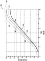
- FIG. 6 a schematic plot 600 representative of a health monitoring process in accordance with an embodiment of the present disclosure is shown.
- Plot 600 has time on the horizontal axis and distance traveled on the vertical axis.
- Plotted on plot 600 is a first motion state sensor signal 602 as generated by a first motion state sensor of a dynamic compensation control system, such as a machine motion state sensor.
- a second motion state sensor signal 604 is also shown and is generated by a second motion state sensor of the dynamic compensation control system, such as an on-car motion state sensor.
- a tolerance 606 is continuously monitored by a computing system.
- the tolerance 606 is a range of distance values that are calculated based on a machine motion state sensor signal.
- the tolerance 606 includes an upper boundary 608 and a lower boundary 610 .
- FIG. 6 illustrates a tolerance 606 that is a fixed or absolute limit (e.g., plus and minus), as an illustrative example. Other tolerance limits, such as relative limits, could also be employed, as will be appreciated by those of skill in the art.
- the health monitoring system will check a measurement of distance traveled that is recorded by the second motion state sensor (e.g., second motion state sensor signal 604 ) against a measurement of distance traveled that is recorded by the first motion state sensor (e.g., first motion state sensor signal 602 ). The health monitoring system will determined if the second motion state sensor signal is within the tolerance 606 . If the second motion state sensor signal 604 exceeds either the upper or lower boundaries 608 , 610 and thus exceeds the tolerance 606 , the health monitoring system may control a dynamic compensation control system to not perform a dynamic compensation control operation at the next landing (i.e., the dynamic compensation control system can be deactivated).
- the health monitoring system can also instruct an elevator machine or controller to perform traditional re-leveling operations at landings until the second motion state sensor signal 604 is measured within the tolerance 606 .
- the second motion state sensor signal 604 is shown deviating outside of the tolerance 606 at point 612 .
- the upper and lower boundaries may have different separations from the first motion state sensor signal 602 .
- FIG. 7 a schematic plot 700 representative of a health monitoring process in accordance with an embodiment of the present disclosure is shown.
- Plot 700 has time on the horizontal axis and distance traveled on the vertical axis.
- Plotted on plot 700 is a first motion state sensor signal 702 as generated by a first motion state sensor of a dynamic compensation control system, such as a machine motion state sensor.
- a second motion state sensor signal 704 is also shown and is generated by a second motion state sensor of the dynamic compensation control system, such as an on-car motion state sensor.
- a tolerance is continuously monitored by a computing system by measuring a distance or separation between the first motion state sensor signal 702 and the second motion state sensor signal 704 .
- the health monitoring system will check a distance traveled as recorded by the first and second motion state sensors and compare the first and second motion state sensor signals 702 , 704 .
- the health monitoring system will compare the two values (e.g., take an absolute value of the difference between the two motion state sensor signals) and determine if the determined difference is within a predefined tolerance value.
- the difference between the motion state sensor signals 702 , 704 is indicated at 706 a , 706 b , 706 c which are difference measurements taken at different times.
- the health monitoring system may control a dynamic compensation control system to not perform a dynamic compensation control operation at the next landing (i.e., the dynamic compensation control system can be deactivated).
- the health monitoring system can also instruct an elevator machine or controller to perform traditional re-leveling operations at landings until a difference between motion state sensor signals is within the tolerance.
- FIG. 8 a flow process 800 for operating an elevator system in accordance with an embodiment of the present disclosure is shown.
- the flow process 800 can be performed as part of a routine or maintenance schedule to monitor operating and/or mechanical conditions of an elevator system.
- the flow process 800 may be a process for monitoring a dynamic compensation control system of an elevator system.
- the elevator system includes an elevator car moveable within an elevator shaft between landings or floors.
- the elevator system further includes a first motion state sensor, such as an elevator machine motion state sensor, and a second motion state sensor that is located on the elevator car (e.g., associated with elevator car guiding devices such as roller guides).
- the first and second motion state sensors are arranged to provide motion state sensor signals to a position control system and/or dynamic compensation control system to perform dynamic compensation control operations when the elevator car is located at a landing.
- a health monitoring system is also in communication with the first and second motion state sensors to receive the motion state sensor signals therefrom.
- the health monitoring system and the dynamic compensation control system are a single unit and further may be process routines (e.g., programs) that are performed using an elevator controller.
- the elevator car is moved in a normal mode of operation, such as between elevator floors.
- the position of the elevator car e.g., movement
- an elevator machine e.g., as shown in FIGS. 1 A- 1 B .
- a first motion state sensor monitors the movement of the elevator car by monitoring a drive characteristic of an elevator machine (e.g., rotations) and a distance of travel can be calculated.
- the second motion state sensor that is on the elevator car can monitor a distance of travel by monitoring revolutions, rotations, or other characteristics of the elevator car itself (or a component thereof, such as a roller guide).
- the health monitoring system will monitor a first motion state sensor signal, as generated by the first motion state sensor.
- the health monitoring system will monitor a second motion state sensor signal, as generated by the second motion state sensor.
- blocks 804 - 806 can be performed simultaneously such that the two motion state sensor signals are monitored simultaneously.
- the determination may be an analysis of the first and second motion state sensor signals that is performed by a computing system.
- the health monitoring system can analyze and monitor for deviation of the second motion state sensor signal from (or relative to) the first motion state sensor signals (e.g., as shown in FIG. 7 ) or can monitor whether the second motion state sensor signal stays within or exceeds a tolerance based on a value of the first motion state sensor signal (e.g., as shown in FIG. 6 ).
- the determination made at block 808 is with respect to an operational status of the second motion state sensor.
- a first operational status may be a working condition (e.g., normal operation) and a second operational status may be a failure condition, wherein failure is determined by a deviation of the second motion state sensor signal relative to the first motion state sensor signal.
- the determination can include a comparison of the second motion state sensor signal to the first motion state sensor signal, and if the comparison is within a predetermined tolerance, it is determined that the second motion state sensor is operating properly, and the flow process 800 continues to block 810 .
- the dynamic compensation control mode can be employed.
- the first and second motion state sensor signals are used to perform dynamic compensation control (e.g., re-leveling) at the landing.
- the health monitoring system will deactivate a dynamic compensation control system. Deactivation may entail merely disabling and/or not running a dynamic compensation control mode of operation. As such, when the elevator car approaches a landing to stop and load/unload passengers, the elevator car will not be subject to dynamic compensation control.
- the motion state of the elevator car relative to the landing will be maintained using a traditional re-leveling mode of operation (e.g., based on the first motion state sensor signal only).
- the health monitoring system can generate a notification that can be transmitted on-site or off-site to indicate that maintenance is required with respect to the dynamic compensation control system.
- the tolerance can be a variable that changes based on a total distance traveled during normal operation mode. That is, the tolerance can be small for short distances of travel of an elevator car, and can increase as a length of travel increases. Further, in some embodiments, the tolerance can be a fixed value for all distances of travel or may be fixed based on a number of landings travelled (e.g., a first tolerance for traveling three of fewer landings, a second tolerance for travel that is four to seven landings, and a third tolerance for travel that is greater than a distance of seven landings). As will be appreciated by those of skill in the art, the tolerance (e.g., absolute values and how implemented) may be based on a particular elevator system and thus various arrangements and configurations are possible without departing from the scope of the present disclosure.
- the improper operation of the second motion state sensor may occur for various reasons, electrical and/or mechanical. However, the precise cause of possible failure or at least improper operation is not required to be known or anticipated. Embodiments of the present disclosure are arranged to enable prevention of unexpected dynamic compensation control operations (e.g., re-leveling by too much or too little distance).
- Various on-car (second) motion state sensor failures may include electrical failures (including, but not limited to, power supply failures, processing failures, connection and/or communication failures, noise on a communication line, etc.) and mechanical failures (including, but not limited to, lack of contact between motion state sensor and roller, lack of contact between roller and guide rail, breakage or damage to a component, partial loss of contact, loss of contact but continued spinning of motion state sensor and/or roller, etc.).
- electrical failures including, but not limited to, power supply failures, processing failures, connection and/or communication failures, noise on a communication line, etc.
- mechanical failures including, but not limited to, lack of contact between motion state sensor and roller, lack of contact between roller and guide rail, breakage or damage to a component, partial loss of contact, loss of contact but continued spinning of motion state sensor and/or roller, etc.
- health monitoring systems in accordance with the present disclosure can improve the quality, reliability, and service of dynamic compensation control systems, ensuring proper installation of on-car motion state sensors (e.g., alignment, contact pressure, etc.), and detecting on-car motion state sensor faults and failure modes that could produce large unexpected motions of the elevator car during loading and unloading operational scenarios. If the on-car motion state sensor fails or does not operate properly during dynamic compensation control mode, the dynamic compensation control system may generate a command that results in the elevator car moving away from floor level unexpectedly. Accordingly, embodiments of the present disclosure can disable the dynamic compensation control system in such instances to prevent the unexpected movement of the elevator car.
- on-car motion state sensors e.g., alignment, contact pressure, etc.
Landscapes
- Engineering & Computer Science (AREA)
- Automation & Control Theory (AREA)
- Maintenance And Inspection Apparatuses For Elevators (AREA)
Abstract
Description
Claims (14)
Priority Applications (1)
| Application Number | Priority Date | Filing Date | Title |
|---|---|---|---|
| US16/000,004 US11548758B2 (en) | 2017-06-30 | 2018-06-05 | Health monitoring systems and methods for elevator systems |
Applications Claiming Priority (2)
| Application Number | Priority Date | Filing Date | Title |
|---|---|---|---|
| US201762527249P | 2017-06-30 | 2017-06-30 | |
| US16/000,004 US11548758B2 (en) | 2017-06-30 | 2018-06-05 | Health monitoring systems and methods for elevator systems |
Publications (2)
| Publication Number | Publication Date |
|---|---|
| US20190002235A1 US20190002235A1 (en) | 2019-01-03 |
| US11548758B2 true US11548758B2 (en) | 2023-01-10 |
Family
ID=62837786
Family Applications (1)
| Application Number | Title | Priority Date | Filing Date |
|---|---|---|---|
| US16/000,004 Active 2041-08-04 US11548758B2 (en) | 2017-06-30 | 2018-06-05 | Health monitoring systems and methods for elevator systems |
Country Status (6)
| Country | Link |
|---|---|
| US (1) | US11548758B2 (en) |
| EP (1) | EP3421400B1 (en) |
| KR (1) | KR102609404B1 (en) |
| CN (1) | CN109205420B (en) |
| AU (1) | AU2018204749B2 (en) |
| ES (1) | ES2809800T3 (en) |
Families Citing this family (9)
| Publication number | Priority date | Publication date | Assignee | Title |
|---|---|---|---|---|
| EP3102522B1 (en) * | 2014-02-06 | 2019-11-13 | Otis Elevator Company | Brake operation management in elevators |
| US10494228B2 (en) * | 2017-02-28 | 2019-12-03 | Otis Elevator Company | Guiding devices for elevator systems having roller guides and motion sensors |
| US11472666B2 (en) * | 2019-04-05 | 2022-10-18 | Otis Elevator Company | Elevator maintenance app matching mechanics position with faults detected |
| US11718500B2 (en) * | 2019-07-10 | 2023-08-08 | Otis Elevator Company | Customer behavior driven predictive maintenance |
| EP3984936B1 (en) * | 2020-10-14 | 2026-02-11 | Otis Elevator Company | Monitoring system for conveyance system |
| EP3984940B1 (en) * | 2020-10-16 | 2025-06-25 | Otis Elevator Company | Elevator monitoring system |
| WO2022091376A1 (en) * | 2020-10-30 | 2022-05-05 | 三菱電機ビルテクノサービス株式会社 | Elevator failure diagnosis device |
| CN114291678B (en) * | 2021-12-30 | 2024-05-03 | 成都科达光电技术有限责任公司 | Method for judging safety state of construction elevator by using multifunctional construction elevator safety monitoring equipment |
| US12054359B1 (en) * | 2023-07-12 | 2024-08-06 | Otis Elevator Company | Roller guide mounted elevator monitoring systems |
Citations (34)
| Publication number | Priority date | Publication date | Assignee | Title |
|---|---|---|---|---|
| US4319665A (en) | 1979-05-11 | 1982-03-16 | Hitachi, Ltd. | AC Elevator control system |
| US4887695A (en) | 1987-11-27 | 1989-12-19 | Inventio Ag | Position control method and apparatus for an elevator drive |
| US5035301A (en) | 1989-07-03 | 1991-07-30 | Otis Elevator Company | Elevator speed dictation system |
| US5274203A (en) | 1989-06-30 | 1993-12-28 | Otis Elevator Company | "Smart" position transducer system for elevators |
| US5304751A (en) | 1991-07-16 | 1994-04-19 | Otis Elevator Company | Elevator horizontal suspensions and controls |
| JPH08301539A (en) | 1995-05-01 | 1996-11-19 | Hitachi Ltd | Elevator control device and control method |
| US5747755A (en) | 1995-12-22 | 1998-05-05 | Otis Elevator Company | Elevator position compensation system |
| US6089355A (en) * | 1997-09-09 | 2000-07-18 | Kabushiki Kaisha Toshiba | Elevator speed controller |
| JP2002241062A (en) | 2001-02-16 | 2002-08-28 | Mitsuru Takayama | Elevator controller |
| EP1278693A1 (en) | 2000-04-27 | 2003-01-29 | Inventio Ag | Device for producing elevator shaft information |
| JP2005051865A (en) | 2003-07-30 | 2005-02-24 | Toshiba Elevator Co Ltd | Motor drive controller for elevator |
| US7007774B2 (en) * | 2002-07-29 | 2006-03-07 | Mitsubishi Denki Kabushiki Kaisha | Active horizontal vibration reducing device for elevator |
| JP3958551B2 (en) | 2001-10-16 | 2007-08-15 | 株式会社日立製作所 | Elevator control method and apparatus |
| JP2009012932A (en) | 2007-07-04 | 2009-01-22 | Toshiba Elevator Co Ltd | Elevator control device |
| EP2048103A1 (en) | 2006-07-27 | 2009-04-15 | Mitsubishi Electric Corporation | Elevator device |
| US7588127B2 (en) | 2004-05-28 | 2009-09-15 | Mitsubishi Denki Kabushiki Kaisha | Elevator rail joint detector and elevator system |
| US7614482B2 (en) * | 2004-05-28 | 2009-11-10 | Mitsubishi Denki Kabushiki Kaisha | Elevator rope slip detector and elevator system |
| US7617911B2 (en) * | 2006-06-21 | 2009-11-17 | Kone Corporation | Method and system for detecting and stopping uncontrolled movement of an elevator car in an elevator |
| US7621377B2 (en) * | 2005-03-24 | 2009-11-24 | Inventio Ag | Elevator with vertical vibration compensation |
| EP1602610B1 (en) | 2004-06-02 | 2010-04-14 | Inventio Ag | Elevator supervision |
| JP2010275078A (en) | 2009-05-29 | 2010-12-09 | Mitsubishi Electric Corp | Elevator control device |
| US7950499B2 (en) | 2005-11-29 | 2011-05-31 | Mitsubishi Electric Corporation | Control apparatus for an elevator responsive to car-mounted position detectors |
| US8006808B2 (en) | 2006-01-30 | 2011-08-30 | Otis Elevator Company | Managing an encoder malfunction in an elevator drive system |
| US8261886B2 (en) * | 2007-06-21 | 2012-09-11 | Mitsubishi Electric Corporation | Safety device for elevator and rope slip detection method |
| CN102762480A (en) | 2010-03-17 | 2012-10-31 | 株式会社日立制作所 | Space-saving elevator |
| EP2527281A2 (en) | 2011-05-25 | 2012-11-28 | Hitachi Ltd. | Elevator |
| US20130118836A1 (en) | 2011-11-15 | 2013-05-16 | Inventio Ag | Elevator with safety device |
| US8746411B2 (en) * | 2008-12-05 | 2014-06-10 | Otis Elevator Company | Elevator car positioning including gain adjustment based upon whether a vibration damper is activated |
| CN104176577A (en) | 2014-07-21 | 2014-12-03 | 日立电梯(中国)有限公司 | Device and method for detecting absolute position of elevator car |
| CN204897072U (en) | 2015-03-09 | 2015-12-23 | 东芝电梯株式会社 | Elevator apparatus |
| US20160023864A1 (en) * | 2013-03-07 | 2016-01-28 | Otis Elevator Company | Active damping of vertical oscillation of a hovering elevator car |
| US20160214832A1 (en) | 2013-09-20 | 2016-07-28 | Mitsubishi Electric Corporation | Elevator apparatus |
| US20160221794A1 (en) * | 2013-11-01 | 2016-08-04 | Kone Corporation | Elevator and method for the use of an elevator control system in monitoring the load of a car and/or to determine the load situation |
| US20170057782A1 (en) | 2014-02-19 | 2017-03-02 | Otis Elevator Company | Improved elevator releveling control |
-
2018
- 2018-06-05 US US16/000,004 patent/US11548758B2/en active Active
- 2018-06-28 KR KR1020180074505A patent/KR102609404B1/en active Active
- 2018-06-29 CN CN201810706256.2A patent/CN109205420B/en active Active
- 2018-06-29 AU AU2018204749A patent/AU2018204749B2/en not_active Ceased
- 2018-06-29 ES ES18180901T patent/ES2809800T3/en active Active
- 2018-06-29 EP EP18180901.3A patent/EP3421400B1/en active Active
Patent Citations (34)
| Publication number | Priority date | Publication date | Assignee | Title |
|---|---|---|---|---|
| US4319665A (en) | 1979-05-11 | 1982-03-16 | Hitachi, Ltd. | AC Elevator control system |
| US4887695A (en) | 1987-11-27 | 1989-12-19 | Inventio Ag | Position control method and apparatus for an elevator drive |
| US5274203A (en) | 1989-06-30 | 1993-12-28 | Otis Elevator Company | "Smart" position transducer system for elevators |
| US5035301A (en) | 1989-07-03 | 1991-07-30 | Otis Elevator Company | Elevator speed dictation system |
| US5304751A (en) | 1991-07-16 | 1994-04-19 | Otis Elevator Company | Elevator horizontal suspensions and controls |
| JPH08301539A (en) | 1995-05-01 | 1996-11-19 | Hitachi Ltd | Elevator control device and control method |
| US5747755A (en) | 1995-12-22 | 1998-05-05 | Otis Elevator Company | Elevator position compensation system |
| US6089355A (en) * | 1997-09-09 | 2000-07-18 | Kabushiki Kaisha Toshiba | Elevator speed controller |
| EP1278693A1 (en) | 2000-04-27 | 2003-01-29 | Inventio Ag | Device for producing elevator shaft information |
| JP2002241062A (en) | 2001-02-16 | 2002-08-28 | Mitsuru Takayama | Elevator controller |
| JP3958551B2 (en) | 2001-10-16 | 2007-08-15 | 株式会社日立製作所 | Elevator control method and apparatus |
| US7007774B2 (en) * | 2002-07-29 | 2006-03-07 | Mitsubishi Denki Kabushiki Kaisha | Active horizontal vibration reducing device for elevator |
| JP2005051865A (en) | 2003-07-30 | 2005-02-24 | Toshiba Elevator Co Ltd | Motor drive controller for elevator |
| US7614482B2 (en) * | 2004-05-28 | 2009-11-10 | Mitsubishi Denki Kabushiki Kaisha | Elevator rope slip detector and elevator system |
| US7588127B2 (en) | 2004-05-28 | 2009-09-15 | Mitsubishi Denki Kabushiki Kaisha | Elevator rail joint detector and elevator system |
| EP1602610B1 (en) | 2004-06-02 | 2010-04-14 | Inventio Ag | Elevator supervision |
| US7621377B2 (en) * | 2005-03-24 | 2009-11-24 | Inventio Ag | Elevator with vertical vibration compensation |
| US7950499B2 (en) | 2005-11-29 | 2011-05-31 | Mitsubishi Electric Corporation | Control apparatus for an elevator responsive to car-mounted position detectors |
| US8006808B2 (en) | 2006-01-30 | 2011-08-30 | Otis Elevator Company | Managing an encoder malfunction in an elevator drive system |
| US7617911B2 (en) * | 2006-06-21 | 2009-11-17 | Kone Corporation | Method and system for detecting and stopping uncontrolled movement of an elevator car in an elevator |
| EP2048103A1 (en) | 2006-07-27 | 2009-04-15 | Mitsubishi Electric Corporation | Elevator device |
| US8261886B2 (en) * | 2007-06-21 | 2012-09-11 | Mitsubishi Electric Corporation | Safety device for elevator and rope slip detection method |
| JP2009012932A (en) | 2007-07-04 | 2009-01-22 | Toshiba Elevator Co Ltd | Elevator control device |
| US8746411B2 (en) * | 2008-12-05 | 2014-06-10 | Otis Elevator Company | Elevator car positioning including gain adjustment based upon whether a vibration damper is activated |
| JP2010275078A (en) | 2009-05-29 | 2010-12-09 | Mitsubishi Electric Corp | Elevator control device |
| CN102762480A (en) | 2010-03-17 | 2012-10-31 | 株式会社日立制作所 | Space-saving elevator |
| EP2527281A2 (en) | 2011-05-25 | 2012-11-28 | Hitachi Ltd. | Elevator |
| US20130118836A1 (en) | 2011-11-15 | 2013-05-16 | Inventio Ag | Elevator with safety device |
| US20160023864A1 (en) * | 2013-03-07 | 2016-01-28 | Otis Elevator Company | Active damping of vertical oscillation of a hovering elevator car |
| US20160214832A1 (en) | 2013-09-20 | 2016-07-28 | Mitsubishi Electric Corporation | Elevator apparatus |
| US20160221794A1 (en) * | 2013-11-01 | 2016-08-04 | Kone Corporation | Elevator and method for the use of an elevator control system in monitoring the load of a car and/or to determine the load situation |
| US20170057782A1 (en) | 2014-02-19 | 2017-03-02 | Otis Elevator Company | Improved elevator releveling control |
| CN104176577A (en) | 2014-07-21 | 2014-12-03 | 日立电梯(中国)有限公司 | Device and method for detecting absolute position of elevator car |
| CN204897072U (en) | 2015-03-09 | 2015-12-23 | 东芝电梯株式会社 | Elevator apparatus |
Non-Patent Citations (1)
| Title |
|---|
| European Search Report for EP Application No. 18180901.3, International Filing Date Jun. 29, 2018, dated Nov. 26, 2018, 11 pages. |
Also Published As
| Publication number | Publication date |
|---|---|
| EP3421400A1 (en) | 2019-01-02 |
| AU2018204749B2 (en) | 2023-11-23 |
| KR102609404B1 (en) | 2023-12-04 |
| CN109205420B (en) | 2021-01-12 |
| ES2809800T3 (en) | 2021-03-05 |
| KR20190003384A (en) | 2019-01-09 |
| AU2018204749A1 (en) | 2019-01-17 |
| US20190002235A1 (en) | 2019-01-03 |
| CN109205420A (en) | 2019-01-15 |
| EP3421400B1 (en) | 2020-05-20 |
Similar Documents
| Publication | Publication Date | Title |
|---|---|---|
| US11548758B2 (en) | Health monitoring systems and methods for elevator systems | |
| US10494228B2 (en) | Guiding devices for elevator systems having roller guides and motion sensors | |
| US11235948B2 (en) | Dynamic compensation control for elevator systems | |
| US10266372B2 (en) | Building settling detection | |
| US12162723B2 (en) | Elevator car position determination | |
| CN101316781A (en) | Arrangement for controlling elevator | |
| JP6987255B2 (en) | Elevator diagnostic system | |
| US11066273B2 (en) | Elevator overtravel testing systems and methods | |
| CN104718148A (en) | Safety device of an elevator system | |
| JP4252330B2 (en) | Elevator rope damping device | |
| EP3351498A1 (en) | Elevator hover mode operation using sensor-based potential load change detection | |
| WO2010067435A1 (en) | Elevator apparatus | |
| EP3553011A1 (en) | Overspeed detection and guiding devices for elevator systems | |
| US20190330015A1 (en) | Elevator safety system | |
| WO2025088681A1 (en) | Elevator device | |
| WO2019077645A1 (en) | Device and method for controlling elevator | |
| US20240409362A1 (en) | Monitoring of elevator pit tie-down and compensation |
Legal Events
| Date | Code | Title | Description |
|---|---|---|---|
| FEPP | Fee payment procedure |
Free format text: ENTITY STATUS SET TO UNDISCOUNTED (ORIGINAL EVENT CODE: BIG.); ENTITY STATUS OF PATENT OWNER: LARGE ENTITY |
|
| AS | Assignment |
Owner name: OTIS ELEVATOR COMPANY, CONNECTICUT Free format text: ASSIGNMENT OF ASSIGNORS INTEREST;ASSIGNORS:ROBERTS, RANDY;PIEDRA, EDWARD;SWAYBILL, BRUCE P.;SIGNING DATES FROM 20180511 TO 20180514;REEL/FRAME:046023/0932 |
|
| STPP | Information on status: patent application and granting procedure in general |
Free format text: DOCKETED NEW CASE - READY FOR EXAMINATION |
|
| STPP | Information on status: patent application and granting procedure in general |
Free format text: NON FINAL ACTION MAILED |
|
| STPP | Information on status: patent application and granting procedure in general |
Free format text: RESPONSE TO NON-FINAL OFFICE ACTION ENTERED AND FORWARDED TO EXAMINER |
|
| STPP | Information on status: patent application and granting procedure in general |
Free format text: FINAL REJECTION MAILED |
|
| STPP | Information on status: patent application and granting procedure in general |
Free format text: ADVISORY ACTION MAILED |
|
| STPP | Information on status: patent application and granting procedure in general |
Free format text: DOCKETED NEW CASE - READY FOR EXAMINATION |
|
| STPP | Information on status: patent application and granting procedure in general |
Free format text: NOTICE OF ALLOWANCE MAILED -- APPLICATION RECEIVED IN OFFICE OF PUBLICATIONS |
|
| STPP | Information on status: patent application and granting procedure in general |
Free format text: PUBLICATIONS -- ISSUE FEE PAYMENT VERIFIED |
|
| STCF | Information on status: patent grant |
Free format text: PATENTED CASE |