EP0406529B1 - Coating device - Google Patents
Coating device Download PDFInfo
- Publication number
- EP0406529B1 EP0406529B1 EP90107009A EP90107009A EP0406529B1 EP 0406529 B1 EP0406529 B1 EP 0406529B1 EP 90107009 A EP90107009 A EP 90107009A EP 90107009 A EP90107009 A EP 90107009A EP 0406529 B1 EP0406529 B1 EP 0406529B1
- Authority
- EP
- European Patent Office
- Prior art keywords
- coating
- roller
- doctor blade
- blade
- throttle
- Prior art date
- Legal status (The legal status is an assumption and is not a legal conclusion. Google has not performed a legal analysis and makes no representation as to the accuracy of the status listed.)
- Expired - Lifetime
Links
Images

Classifications
-
- B—PERFORMING OPERATIONS; TRANSPORTING
- B05—SPRAYING OR ATOMISING IN GENERAL; APPLYING FLUENT MATERIALS TO SURFACES, IN GENERAL
- B05C—APPARATUS FOR APPLYING FLUENT MATERIALS TO SURFACES, IN GENERAL
- B05C11/00—Component parts, details or accessories not specifically provided for in groups B05C1/00 - B05C9/00
- B05C11/02—Apparatus for spreading or distributing liquids or other fluent materials already applied to a surface ; Controlling means therefor; Control of the thickness of a coating by spreading or distributing liquids or other fluent materials already applied to the coated surface
- B05C11/023—Apparatus for spreading or distributing liquids or other fluent materials already applied to a surface
- B05C11/025—Apparatus for spreading or distributing liquids or other fluent materials already applied to a surface with an essentially cylindrical body, e.g. roll or rod
-
- B—PERFORMING OPERATIONS; TRANSPORTING
- B05—SPRAYING OR ATOMISING IN GENERAL; APPLYING FLUENT MATERIALS TO SURFACES, IN GENERAL
- B05C—APPARATUS FOR APPLYING FLUENT MATERIALS TO SURFACES, IN GENERAL
- B05C3/00—Apparatus in which the work is brought into contact with a bulk quantity of liquid or other fluent material
- B05C3/18—Apparatus in which the work is brought into contact with a bulk quantity of liquid or other fluent material only one side of the work coming into contact with the liquid or other fluent material
-
- D—TEXTILES; PAPER
- D21—PAPER-MAKING; PRODUCTION OF CELLULOSE
- D21H—PULP COMPOSITIONS; PREPARATION THEREOF NOT COVERED BY SUBCLASSES D21C OR D21D; IMPREGNATING OR COATING OF PAPER; TREATMENT OF FINISHED PAPER NOT COVERED BY CLASS B31 OR SUBCLASS D21G; PAPER NOT OTHERWISE PROVIDED FOR
- D21H23/00—Processes or apparatus for adding material to the pulp or to the paper
- D21H23/02—Processes or apparatus for adding material to the pulp or to the paper characterised by the manner in which substances are added
- D21H23/22—Addition to the formed paper
- D21H23/32—Addition to the formed paper by contacting paper with an excess of material, e.g. from a reservoir or in a manner necessitating removal of applied excess material from the paper
- D21H23/34—Knife or blade type coaters
- D21H23/36—Knife or blade forming part of the fluid reservoir, e.g. puddle-type trailing blade or short-dwell coaters
-
- B—PERFORMING OPERATIONS; TRANSPORTING
- B05—SPRAYING OR ATOMISING IN GENERAL; APPLYING FLUENT MATERIALS TO SURFACES, IN GENERAL
- B05C—APPARATUS FOR APPLYING FLUENT MATERIALS TO SURFACES, IN GENERAL
- B05C11/00—Component parts, details or accessories not specifically provided for in groups B05C1/00 - B05C9/00
- B05C11/02—Apparatus for spreading or distributing liquids or other fluent materials already applied to a surface ; Controlling means therefor; Control of the thickness of a coating by spreading or distributing liquids or other fluent materials already applied to the coated surface
- B05C11/04—Apparatus for spreading or distributing liquids or other fluent materials already applied to a surface ; Controlling means therefor; Control of the thickness of a coating by spreading or distributing liquids or other fluent materials already applied to the coated surface with blades
Landscapes
- Coating Apparatus (AREA)
- Piezo-Electric Or Mechanical Vibrators, Or Delay Or Filter Circuits (AREA)
- Ultra Sonic Daignosis Equipment (AREA)
- Medicines Containing Antibodies Or Antigens For Use As Internal Diagnostic Agents (AREA)
- Encapsulation Of And Coatings For Semiconductor Or Solid State Devices (AREA)
- Seal Device For Vehicle (AREA)
- Glass Compositions (AREA)
- Application Of Or Painting With Fluid Materials (AREA)
- Paints Or Removers (AREA)
- Finger-Pressure Massage (AREA)
- Vehicle Interior And Exterior Ornaments, Soundproofing, And Insulation (AREA)
- Electrochromic Elements, Electrophoresis, Or Variable Reflection Or Absorption Elements (AREA)
Abstract
Description
Die Erfindung betrifft eine Streicheinrichtung nach dem Oberbegriff des Patentanspruchs 1. Eine solche Streicheinrichtung ist bekannt aus der FR-A 2 606 673. Bei dieser Einrichtung ist ein Ablaufkanal vorgesehen, der den Überschuß der Streichmasse aus der Auftragskammer zunächst entlang dem Rakelelement abführt. Die Zufuhr der Streichmasse erfolgt entlang der Bahn und nicht entlang dem Rakelelement. Es müssen dabei Unterbrechungen des Zufuhr- und Abfuhrkanals in einem gewissen Bereich derselben vorgesehen werden, damit diese Strömungsführung möglich ist. Dazu ist ein Strömungskörper vorgesehen, der die entlang der Warenbahn zum Rakelelement strömende Streichmasse von der den Auftragsraum verlassenden Überschußmenge der Streichmasse trennt.The invention relates to a coating device according to the preamble of
Gemäß der DE-A-36 16 645 ist ein Auftragswerk vorgesehen, bei welchem auch durch einen Deckkörper die Streichmasse entlang der Warenbahn dem Rakelelement bzw. dessen an der Bahn anliegender Dosierkante zugeführt wird. Dabei wird ein Überschuß an Streichmasse am bahneinlaufseitigen Ende des Deckkörpers aus dem Auftragsraum abgeführt. Dabei soll ein hydrodynamischer Druck im Bereich des Deckkörpers und der Warenbahn erzeugt werden. Ferner wird der Zweck verfolgt, durch einen genau definierten Ableitpunkt der Streichmasse am bahneinlaufseitigen Ende des Auftragswerks das Mitreißen von Luft durch die Warenbahn in den Auftragsraum hinein zu verhindern.According to DE-A-36 16 645, an application unit is provided in which the coating slip is also supplied to the doctor element or its metering edge lying against the web through a cover body along the web. In this case, an excess of coating slip is removed from the application area at the end of the cover body on the web entry side. A hydrodynamic pressure is to be generated in the area of the cover body and the web. Furthermore, the purpose is pursued, by means of a precisely defined discharge point of the coating slip at the end of the application unit at the web entry end, to prevent air being carried along by the web into the order area.
Die Aufgabe der Erfindung ist es, die Qualität des aufgetragenen Strichs hinsichtlich Gleichmäßigkeit zu verbessern. Wegen der hohen Bahngeschwindigkeiten scheint es bei den bisher bekannten Auftragseinrichtungen der gattungsgemäßen Art schwierig zu sein, auftretende Turbulenzen in der Streichmasse zu verhindern.The object of the invention is to improve the quality of the applied stroke with regard to uniformity. Because of the high web speeds, it seems to be difficult with the previously known application devices of the generic type to prevent turbulence occurring in the coating slip.
Die genannte Aufgabe wird erfindungsgemäß durch die kennzeichnenden Merkmale des Patentanspruchs 1 gelöst.According to the invention, this object is achieved by the characterizing features of
Nachfolgend wird die Erfindung anhand mehrerer in der Zeichnung dargestellte Ausführungsbeispiele erläutert.The invention is explained below using several exemplary embodiments shown in the drawing.
Dabei stellt:
- Fig. 1
- prinzipmäßig einen Querschnitt durch die erfindungsgemäße Streicheinrichtung,
- Fig. 2
- eine andere Ausführungsform einer ähnlichen Darstellung,
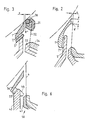
- Fig. 3
- eine wieder andere Ausführungsform,
- Fig. 4
- eine wieder andere Ausführungsform mit einem Drosselschieber,
- Fig. 5
- teilweise einen Längsschnitt zu Figur 4 gemäß dortiger Schnittangabe und
- Fig. 6
- eine Ausführungsform
ähnlich Figur 2.
- Fig. 1
- in principle a cross section through the coating device according to the invention,
- Fig. 2
- another embodiment of a similar representation,
- Fig. 3
- yet another embodiment,
- Fig. 4
- yet another embodiment with a throttle valve,
- Fig. 5
- partially a longitudinal section to Figure 4 according to the section and
- Fig. 6
- an embodiment similar to Figure 2.
Die Warenbahn wird von der Gegenwalze 2 im Bereich der Streichklinge 4 geführt. Die Streichmasse gelangt aus der Kammer 10 über den Mündungskanal 11′ zur Mündung 11 und von dort zur Streichklinge 4. Die Streichmasse wird mit einem gewissen Überschuß zugeführt, die jedoch in diesem Fall wesentlich kleiner sein kannn als bei den bisher bekannten Streicheinrichtungen. Eine obere Platte 1 als Deckkörper bildet gegenüber der Streichklinge 4 den Drosselspalt 8 von einer Weite (Breite) zwischen 3 und 15 mm, vorzugsweise zwischen 5 und 8 mm. Die Länge dieses Kanals beträgt zwischen 5 und 25 mm, vorzugsweise zwischen 5 und 15 mm. Die Spitze 16 der Platte 1 (also die höchstens mit einem Radius von 1 mm abgerundete, der Gegenwalze 2 nahe Kante) ist von der Gegenwalze 2 etwa 3 bis 10 mm entfernt. Die Platte 1 bildet mit einer weiteren Platte 5 als Basis-Deckkörper einen vom Auftragsraum 9 an der Streichklinge 4, wo die Streichmasse von der Mündung 11 zur Abstreifkante der Streichklinge fließt, wegführenden, weiteren Drosselkanal (Abflußkanal) 7, der sich hier im wesentlichen im Bereich zwischen der Mündung 11 und der vorderen Begrenzungswand 13 der Mündung 11 bzw. des Mündungskanals 11′ und der Kammer 10 erstreckt. Seine Höhe beträgt etwa zwischen 3 und 6 mm und seine Länge im wesentlichen zwischen dem Zehn- und Zwanzigfachen der angegebenen Höhe.The material web is guided by the
Die Drosselkanäle sind in Schnitten parallel zur Mittellängsachse der Gegenwalze 2 praktisch schlitzförmig, weil sie in dieser Richtung eine Gesamtlänge entsprechend der Länge der Gegenwalze haben, die z.B. bei 8 m Länge der Gegenwalze 2 und einer Kanal-(Schlitz)-Hohe von 5 oder 8 mm (siehe z.B. "e") letztere um Größenordnungen übertrifft (siehe z.B. auch Fig. 5).The throttle ducts are practically slit-shaped in sections parallel to the central longitudinal axis of the
Vorzugsweise befindet sich zwischen der Rückwand 17 des Mündungskanals 11', und der zweiten Platte 5 im Bereich derselben eine Verengungsstelle 18. Man kann dadurch den Fluß der Streichmasse noch mehr vergleichmäßigen.There is preferably a
Durch den zweiten Drosselkanal 7 fließt im wesentlichen die im Überschuß zugeführte Menge der Streichmasse ab.Through the
Es kann ebenso gut auch die Auftragskammer die Streichmasse direkt der Walze 2 zuführen, die dann in einem anderen Bereich von der Warenbahn umschlungen oder berührt ist, in welchem dann die Übertragung der Streichmasse auf die Warenbahn erfolgt.It is also possible for the application chamber to feed the coating slip directly to the
In Figur 2 ist der Vollständigkeit halber noch eine andere mögliche Ausführungsform von Basiskörper und Deckkörper dargestellt. Die Bezugszeichen sind jeweils mit einem zusätzlichen Apostroph versehen. Die Drosselkanäle erfüllen dabei jeweils die gestellten Bedingungen. Auch das Merkmal des Anspruchs 2 ist erfüllt.For the sake of completeness, FIG. 2 shows yet another possible embodiment of the base body and cover body. The reference symbols are each provided with an additional apostrophe. The throttle channels each meet the conditions. The feature of
In Figur 3 ist dargestellt, daß als Rakelelement auch eine Rollrakel 30 in Frage kommt, die in einem Rakelbett 31 drehbar geführt ist, welches an einer als Blattfeder ausgeführten Tragfeder 32 in der Rakel-Klemmhalterung 33, 34 befestigt ist. Dort wird von dem Deckkörper 1‴ der zweite Drosselkanal 8‴ gegenüber der Rakelhalterung 31 der Rollrakel 30 gebildet.In FIG. 3 it is shown that a
In Figur 4 und 5 ist gezeigt, daß der Drosselkanal 7‴ durch einen Drosselschieber 21 mit Drosselfenstern 22 in seiner Drosselstärke gesteuert werden kann. Jedem Schieber ist eine Drosselleiste 24 mit entsprechenden Fenstern 25 zugeordnet. Die Drosselwirkung des Drosselkanals kann auch im wesentlichen allein auf der Wirkung dieses Schiebers 21 beruhen. Diese Ausführungsform läßt sich natürlich in sehr umfassender Weise an die verschiedensten Verhältnisse des Streichprozesses, z.B. auch die Parameter der Streichmasse wie z.B. deren Konsistenz, anpassen.In Figures 4 and 5 it is shown that the
In Fig. 6 ist eine weitere Variante der erfindungsgemäßen Anordnung dargestellt, wobei der Deckkörper 36 direkt mit einer sehr dick ausgebildeten Vorderwand 43 der Mündung 41 der Kammer 50 für die Streichmasse den ersten Drosselkanal 37 bildet. Dies ist dann besonders vorteilhaft, wenn gerade diese Vorderwand 43 ein wesentlich tragendes Bauteil der Streicheinrichtung bzw. des Tragbalkens für die Streichklinge 4 bildet. Strichpunktiert ist dort dargestellt, wie durch einen nasenförmigen Vorsprung 44 der Vorderwand 43 eine Verengungsstelle am Austritt des Mündungskanals 41 gebildet werden kann.6 shows a further variant of the arrangement according to the invention, the
Es ist üblich, die Streichklinge 4 durch ein in ihrem freien Bereich angreifendes Druckstück einzustellen, das längs der Achse der Gegenwalze bzw. der Breite der Papierbahn auch unterteilt sein kann, um unterschiedliche Preßdrücke auf die Streichklinge 4 auszuüben. Dadurch kommt es zu einer Durchbiegung derselben, so daß der zweite Drosselkanal 8, 8′, 8˝ usw. ziemlich stark in seiner Dimension verändert werden könnte. Dies wird dann ausgeschlossen, wenn man eine Streicheinrichtung anwendet, bei der der Anliegewinkel der Streichklinge 4 an der Gegenwalze bzw. Papierbahn durch entsprechende Schwenkverhältnisse konstantgehalten wird. Eine solche Einrichtung ist u.a. bekanntgeworden aus der US-A-46 37 338. Noch verschiedene andere konstruktive Möglichkeiten in dieser Hinsicht sind bekannt. Bei diesen Einrichtungen wird der Tragbalken samt der Kammer für die Streichmasse einschließlich deren Mündung in die Auftragszone und damit auch der Deckkörper und gegenbenenfalls der Basiskörper in gleichem Maße mitgeschwenkt, wie sich die Winkellage der Einspannung der Streichklinge ändert. Dadurch bleiben die Verhältnisse im wesentlichen auch im Bereich des zweiten Drosselkanals bei allen Betriebszuständen erhalten, so daß sich die Dimensionen des zweiten Drosselkanals dabei nicht wesentlich ändern.It is customary to adjust the doctor blade 4 by means of a pressure piece engaging in its free area, which can also be divided along the axis of the counter roller or the width of the paper web in order to exert different pressures on the doctor blade 4. This leads to a deflection of the same, so that the
Claims (10)
- A coating means, particularly a means of coating continuous webs of material consisting of paper or card, whereby in the region of a roller guiding the web of material or directly at the roller there is a coating doctor blade (4, 30) of which the coating edge engages the web or is applied to the web along a coating line, the coating composition being contained in a chamber (10) in which it is kept at an aboveatmospheric pressure and out of which the coating composition can be fed via a mouth extending parallel with the web of material or counter-roller and extending over the width of the web of material, being fed to this latter or roller or coating blade or doctor blade, any excess coating composition being withdrawn from the area at least close to the coating doctor blade through at least one or a plurality of at least mutually parallel passages (7, 7', 7'', 7'''; 22, 25, 37) which follow one another in the direction of the axis of rotation of the roller and to an area which is remote from the roller, a covering member (1, 1', 1''; 35, 36) moving close to the roller at least in its area which is close to the coating doctor blade (4, 30) while the draw-off passage or passages (7, 7', 7'', 7'''; 22, 25, 37) are formed on the opposite boundary wall which is remote from the roller, characterised in that except for an area close to the coating edge or line of the coating doctor blade (4, 30), the covering body (1, 1', 1''; 35, 36) forms a throttle gap or throttle passage (8, 8', 8'') at the coating doctor blade (4, 30) through the coating composition flows to the coating edge or line of the coating doctor blade (4, 30) and in that the draw-off passage (7, 7', 7'', 7''', 37) is constructed in cross-section parallel with the axis of rotation of the roller so that it is shaped like a slit with a considerable throttle action over the entire roller length or correspondingly the draw-off passages distributed over the width of the web of material are constructed with a regulable throttle means (21-25).
- A coating means according to Claim 1, characterised in that the second throttle passage (8) has in the direction of flow a length (f) along the coating blade or doctor blade mounting of between 5 and 25 mm and preferably between 5 and 15 mm and a clearance (e) of between 3 and 15 mm and preferably between 5 and 8 mm.
- A coating means according to Claim 1 or 2, characterised in that a base body (5, 5', 5'') is provided between the mouth (11) of the applicator chamber (10) or its mouth passage (11') and the cover body (1, 1', 1'', 1'''), the mutually facing surfaces of the base body (5, 5', 5'') and of the cover body forming the discharge passage (7, 7', 7'', 7'''; 22, 37).
- A means according to one of Claims 1 to 3, characterised in that the cover body (1) has at the end of the second throttle passage (8) formed by the coating blade (4) or doctor blade mounting, and in the area close to the coating edge of the doctor blade element, an edge the radius of the rounded edge being at most 2 but preferably about 1 mm and in that it is at a distance (s) of between 3 and 15 mm and preferably between 5 and 10 mm from the counter-roller (2).
- A means according to one of Claims 3 or 4, characterised in that the base body (5) extends as far as the coating blade (4) or doctor blade mounting up to a distance which is not more than 10 mm greater than the distance between the cover body (1) and the coating blade (4) or doctor blade holder and which is at least the same as the clearance or inside diameter (e) of the second throttle passage (8) formed on the coating doctor blade (4, 30).
- A means according to one of Claims 3 to 5, characterised in that at its edge close to the coating blade (4) or doctor blade mounting the base body (5) is rounded off in the region of the first throttle passage (7) to a radius of at least 5 mm.
- A means according to one of Claims 1 to 6, characterised in that the height (inside diameter) of the first throttle passage (7) is between 3 and 6 mm.
- A means according to Claim 7, characterised in that the length of the first throttle passage (7) is ten to twenty times its height.
- A means according to Claims 1 to 7, characterised in that the throttle intensity of the first throttle passage (7''') can be regulated by means of a sliding throttle valve (21) having apertures (22).
- A coating means according to one of Claims 1 to 9, characterised in that the cover body (1), the discharge port (7) and the second throttle passage (8) extend over substantially the entire length of the coating blade (4) or doctor blade mounting (31), the cover body (1) being constructed substantially as a profile strip or plate and being plate- or shell-shaped, its distance from both the working edge of the coating blade (4) or roller doctor blade (30) as well as from the counter-roller increasing more and more by at least 1 mm (distance from the counter-roller) for every 10 mm distance from the working edge.
Applications Claiming Priority (4)
| Application Number | Priority Date | Filing Date | Title |
|---|---|---|---|
| DE3920381 | 1989-06-22 | ||
| DE3920381 | 1989-06-22 | ||
| DE3942590A DE3942590C2 (en) | 1989-06-22 | 1989-12-22 | Coating device |
| DE3942590 | 1989-12-22 |
Publications (3)
| Publication Number | Publication Date |
|---|---|
| EP0406529A2 EP0406529A2 (en) | 1991-01-09 |
| EP0406529A3 EP0406529A3 (en) | 1991-10-23 |
| EP0406529B1 true EP0406529B1 (en) | 1994-06-29 |
Family
ID=25882200
Family Applications (1)
| Application Number | Title | Priority Date | Filing Date |
|---|---|---|---|
| EP90107009A Expired - Lifetime EP0406529B1 (en) | 1989-06-22 | 1990-04-11 | Coating device |
Country Status (9)
| Country | Link |
|---|---|
| US (1) | US5078081A (en) |
| EP (1) | EP0406529B1 (en) |
| JP (1) | JPH0330862A (en) |
| AT (1) | ATE107981T1 (en) |
| BR (1) | BR9002989A (en) |
| CA (1) | CA2019703A1 (en) |
| ES (1) | ES2055823T3 (en) |
| FI (1) | FI902995A0 (en) |
| NO (1) | NO902079L (en) |
Families Citing this family (11)
| Publication number | Priority date | Publication date | Assignee | Title |
|---|---|---|---|---|
| US5133996A (en) * | 1991-10-29 | 1992-07-28 | Beloit Corporation | Method and apparatus for coating a web |
| US5376177A (en) * | 1993-08-09 | 1994-12-27 | Macmillan Bloedel Limited | Coat weight profiling |
| US5599369A (en) * | 1994-04-29 | 1997-02-04 | Owens-Brockway Glass Container Inc. | Hood for metal-oxide vapor coating glass containers |
| DE4444779B4 (en) * | 1994-12-15 | 2005-08-04 | Voith Sulzer Papiermaschinen Gmbh | Device for applying a liquid or pasty medium to a moving material web, in particular of paper or cardboard |
| US5599393A (en) * | 1995-04-25 | 1997-02-04 | Macmillan Bloedel Limited | Metering rod coaters |
| DE19723458A1 (en) | 1997-06-04 | 1998-12-10 | Voith Sulzer Papiermasch Gmbh | Device and method for applying a liquid or pasty medium to a moving surface |
| US5902401A (en) * | 1997-07-09 | 1999-05-11 | Pevifibe Papers Inc. | Coater head |
| US6555162B1 (en) * | 1999-01-14 | 2003-04-29 | Nok Kluber Co., Ltd | Coating layer forming machine and method of forming it |
| JP4830843B2 (en) * | 2006-12-21 | 2011-12-07 | 東洋紡績株式会社 | Reaction cup container and reaction measurement instrument set |
| EP2353736A1 (en) * | 2010-01-29 | 2011-08-10 | 3M Innovative Properties Company | Continuous process for forming a multilayer film and multilayer film prepared by such method |
| MX358309B (en) * | 2011-10-19 | 2018-08-14 | 3M Innovative Properties Co | Articles with thin melt coatings and methods for making same. |
Citations (2)
| Publication number | Priority date | Publication date | Assignee | Title |
|---|---|---|---|---|
| DE3612248A1 (en) * | 1985-05-09 | 1986-11-27 | Consolidated Papers Inc., Wisconsin Rapids, Wis. | PAINTING DEVICE |
| DE3513063C2 (en) * | 1985-04-12 | 1988-12-29 | Jagenberg Ag, 4000 Duesseldorf, De |
Family Cites Families (10)
| Publication number | Priority date | Publication date | Assignee | Title |
|---|---|---|---|---|
| SE360408B (en) * | 1968-12-30 | 1973-09-24 | Waertsilae Oy Ab | |
| US4405661A (en) * | 1981-09-10 | 1983-09-20 | Beloit Corporation | Blade type fountain coater and method |
| DE3338095A1 (en) * | 1983-10-20 | 1985-05-09 | J.M. Voith Gmbh, 7920 Heidenheim | PAINTING DEVICE |
| CH663362A5 (en) * | 1984-01-07 | 1987-12-15 | Jagenberg Ag | DEVICE FOR COATING MATERIAL SHEETS RUNNING ON A SUPPORT ROLLER WITH ADJUSTABLE APPLICATION THICKNESS. |
| FI71081C (en) * | 1984-05-11 | 1986-11-24 | Waertsilae Oy Ab | coating method |
| DE3438380A1 (en) * | 1984-10-19 | 1986-04-24 | J.M. Voith Gmbh, 7920 Heidenheim | COATING DEVICE FOR COATING RUNNING PRODUCTS |
| DE3505769A1 (en) * | 1985-02-20 | 1986-08-21 | J.M. Voith Gmbh, 7920 Heidenheim | PAINTING DEVICE |
| DE3616645A1 (en) * | 1986-05-16 | 1987-11-19 | Voith Gmbh J M | PAINTING DEVICE |
| FI81640C (en) * | 1986-11-14 | 1990-11-12 | Valmet Paper Machinery Inc | Short-dwell coating device for coating a web of material with coating mass |
| DE3734900A1 (en) * | 1987-05-07 | 1988-12-01 | Voith Gmbh J M | DEVICE FOR COATING A RUNNING PAPER OR CARDBOARD |
-
1990
- 1990-04-11 EP EP90107009A patent/EP0406529B1/en not_active Expired - Lifetime
- 1990-04-11 AT AT90107009T patent/ATE107981T1/en active
- 1990-04-11 ES ES90107009T patent/ES2055823T3/en not_active Expired - Lifetime
- 1990-05-10 NO NO90902079A patent/NO902079L/en unknown
- 1990-06-14 FI FI902995A patent/FI902995A0/en not_active IP Right Cessation
- 1990-06-19 US US07/540,476 patent/US5078081A/en not_active Expired - Fee Related
- 1990-06-21 BR BR909002989A patent/BR9002989A/en not_active IP Right Cessation
- 1990-06-22 JP JP2163058A patent/JPH0330862A/en active Pending
- 1990-06-22 CA CA002019703A patent/CA2019703A1/en not_active Abandoned
Patent Citations (2)
| Publication number | Priority date | Publication date | Assignee | Title |
|---|---|---|---|---|
| DE3513063C2 (en) * | 1985-04-12 | 1988-12-29 | Jagenberg Ag, 4000 Duesseldorf, De | |
| DE3612248A1 (en) * | 1985-05-09 | 1986-11-27 | Consolidated Papers Inc., Wisconsin Rapids, Wis. | PAINTING DEVICE |
Also Published As
| Publication number | Publication date |
|---|---|
| ES2055823T3 (en) | 1994-09-01 |
| EP0406529A3 (en) | 1991-10-23 |
| JPH0330862A (en) | 1991-02-08 |
| CA2019703A1 (en) | 1990-12-22 |
| ATE107981T1 (en) | 1994-07-15 |
| NO902079L (en) | 1990-12-27 |
| US5078081A (en) | 1992-01-07 |
| EP0406529A2 (en) | 1991-01-09 |
| NO902079D0 (en) | 1990-05-10 |
| BR9002989A (en) | 1991-08-20 |
| FI902995A0 (en) | 1990-06-14 |
Similar Documents
| Publication | Publication Date | Title |
|---|---|---|
| EP0147536B1 (en) | Apparatus for evenly distributing a liquid flow over a given width | |
| AT392807B (en) | FABRIC DRAIN FOR A PAPER MACHINE OR THE LIKE. | |
| DE3420412C2 (en) | Coating device for coating running webs | |
| DE3438380A1 (en) | COATING DEVICE FOR COATING RUNNING PRODUCTS | |
| DE3338095A1 (en) | PAINTING DEVICE | |
| DE3336552C2 (en) | Coating device for coating moving webs of material | |
| EP0406529B1 (en) | Coating device | |
| DE4432177A1 (en) | An applicator gap is adjustable as pulp coat flows on moving paper web | |
| DE3931793A1 (en) | A DEVICE FOR COATING A DRIVING TRAIN | |
| EP0826824B1 (en) | Coating device for applying directly or indirectly a fluid or pasty coating colour onto a moving web, especially of paper or board | |
| DE19651739A1 (en) | Web coating applicator | |
| DE1511218C3 (en) | Paper pulp feed device for paper machines | |
| DE19602483C1 (en) | Precision adjustable roller squeegee assembly for e.g. paper coater | |
| DE3605409C2 (en) | ||
| EP0882839B1 (en) | Apparatus for the application of a liquid or pasty fluid to a moving web | |
| EP0571849A1 (en) | Coating device for moving webs | |
| DE2607822B2 (en) | Headbox for paper machines | |
| DE4116729C2 (en) | Nozzle-like coating device for applying a coating slip to a running paper web | |
| DE3942590C2 (en) | Coating device | |
| DE19827712A1 (en) | Device for the direct or indirect application of a liquid or pasty application medium to a running material web | |
| DE4230276A1 (en) | Coating device for running webs, especially paper or cardboard | |
| DE4402626C2 (en) | Device for spreading a paper web | |
| EP0848109A1 (en) | Device for applying directly or indirectly fluid or pasty material onto a moving web | |
| DE4327544C1 (en) | Dosing system | |
| EP0726358B1 (en) | Apparatus for impregnating a web of porous material |
Legal Events
| Date | Code | Title | Description |
|---|---|---|---|
| PUAI | Public reference made under article 153(3) epc to a published international application that has entered the european phase |
Free format text: ORIGINAL CODE: 0009012 |
|
| AK | Designated contracting states |
Kind code of ref document: A2 Designated state(s): AT CH DE ES FR GB IT LI SE |
|
| 17P | Request for examination filed |
Effective date: 19901220 |
|
| PUAL | Search report despatched |
Free format text: ORIGINAL CODE: 0009013 |
|
| AK | Designated contracting states |
Kind code of ref document: A3 Designated state(s): AT CH DE ES FR GB IT LI SE |
|
| 17Q | First examination report despatched |
Effective date: 19921008 |
|
| GRAA | (expected) grant |
Free format text: ORIGINAL CODE: 0009210 |
|
| AK | Designated contracting states |
Kind code of ref document: B1 Designated state(s): AT CH DE ES FR GB IT LI SE |
|
| REF | Corresponds to: |
Ref document number: 107981 Country of ref document: AT Date of ref document: 19940715 Kind code of ref document: T |
|
| ET | Fr: translation filed | ||
| GBT | Gb: translation of ep patent filed (gb section 77(6)(a)/1977) |
Effective date: 19940701 |
|
| REF | Corresponds to: |
Ref document number: 59006286 Country of ref document: DE Date of ref document: 19940804 |
|
| REG | Reference to a national code |
Ref country code: ES Ref legal event code: FG2A Ref document number: 2055823 Country of ref document: ES Kind code of ref document: T3 |
|
| ITF | It: translation for a ep patent filed |
Owner name: STUDIO TORTA SOCIETA' SEMPLICE |
|
| EAL | Se: european patent in force in sweden |
Ref document number: 90107009.4 |
|
| PGFP | Annual fee paid to national office [announced via postgrant information from national office to epo] |
Ref country code: ES Payment date: 19950317 Year of fee payment: 6 |
|
| PGFP | Annual fee paid to national office [announced via postgrant information from national office to epo] |
Ref country code: GB Payment date: 19950320 Year of fee payment: 6 |
|
| PGFP | Annual fee paid to national office [announced via postgrant information from national office to epo] |
Ref country code: FR Payment date: 19950404 Year of fee payment: 6 |
|
| PGFP | Annual fee paid to national office [announced via postgrant information from national office to epo] |
Ref country code: SE Payment date: 19950411 Year of fee payment: 6 Ref country code: AT Payment date: 19950411 Year of fee payment: 6 |
|
| PLBE | No opposition filed within time limit |
Free format text: ORIGINAL CODE: 0009261 |
|
| STAA | Information on the status of an ep patent application or granted ep patent |
Free format text: STATUS: NO OPPOSITION FILED WITHIN TIME LIMIT |
|
| PGFP | Annual fee paid to national office [announced via postgrant information from national office to epo] |
Ref country code: DE Payment date: 19950517 Year of fee payment: 6 |
|
| PGFP | Annual fee paid to national office [announced via postgrant information from national office to epo] |
Ref country code: CH Payment date: 19950526 Year of fee payment: 6 |
|
| 26N | No opposition filed | ||
| PG25 | Lapsed in a contracting state [announced via postgrant information from national office to epo] |
Ref country code: GB Effective date: 19960411 Ref country code: AT Effective date: 19960411 |
|
| PG25 | Lapsed in a contracting state [announced via postgrant information from national office to epo] |
Ref country code: SE Effective date: 19960412 Ref country code: ES Free format text: LAPSE BECAUSE OF NON-PAYMENT OF DUE FEES Effective date: 19960412 |
|
| PG25 | Lapsed in a contracting state [announced via postgrant information from national office to epo] |
Ref country code: LI Effective date: 19960430 Ref country code: CH Effective date: 19960430 |
|
| GBPC | Gb: european patent ceased through non-payment of renewal fee |
Effective date: 19960411 |
|
| REG | Reference to a national code |
Ref country code: CH Ref legal event code: PL |
|
| PG25 | Lapsed in a contracting state [announced via postgrant information from national office to epo] |
Ref country code: FR Effective date: 19961227 |
|
| PG25 | Lapsed in a contracting state [announced via postgrant information from national office to epo] |
Ref country code: DE Effective date: 19970101 |
|
| EUG | Se: european patent has lapsed |
Ref document number: 90107009.4 |
|
| REG | Reference to a national code |
Ref country code: FR Ref legal event code: ST |
|
| REG | Reference to a national code |
Ref country code: ES Ref legal event code: FD2A Effective date: 19990201 |
|
| PG25 | Lapsed in a contracting state [announced via postgrant information from national office to epo] |
Ref country code: IT Free format text: LAPSE BECAUSE OF NON-PAYMENT OF DUE FEES;WARNING: LAPSES OF ITALIAN PATENTS WITH EFFECTIVE DATE BEFORE 2007 MAY HAVE OCCURRED AT ANY TIME BEFORE 2007. THE CORRECT EFFECTIVE DATE MAY BE DIFFERENT FROM THE ONE RECORDED. Effective date: 20050411 |