EP0826824B1 - Coating device for applying directly or indirectly a fluid or pasty coating colour onto a moving web, especially of paper or board - Google Patents
Coating device for applying directly or indirectly a fluid or pasty coating colour onto a moving web, especially of paper or board Download PDFInfo
- Publication number
- EP0826824B1 EP0826824B1 EP97109821A EP97109821A EP0826824B1 EP 0826824 B1 EP0826824 B1 EP 0826824B1 EP 97109821 A EP97109821 A EP 97109821A EP 97109821 A EP97109821 A EP 97109821A EP 0826824 B1 EP0826824 B1 EP 0826824B1
- Authority
- EP
- European Patent Office
- Prior art keywords
- coating
- edge limiting
- metering gap
- coating edge
- applicator unit
- Prior art date
- Legal status (The legal status is an assumption and is not a legal conclusion. Google has not performed a legal analysis and makes no representation as to the accuracy of the status listed.)
- Expired - Lifetime
Links
Images


Classifications
-
- D—TEXTILES; PAPER
- D21—PAPER-MAKING; PRODUCTION OF CELLULOSE
- D21H—PULP COMPOSITIONS; PREPARATION THEREOF NOT COVERED BY SUBCLASSES D21C OR D21D; IMPREGNATING OR COATING OF PAPER; TREATMENT OF FINISHED PAPER NOT COVERED BY CLASS B31 OR SUBCLASS D21G; PAPER NOT OTHERWISE PROVIDED FOR
- D21H23/00—Processes or apparatus for adding material to the pulp or to the paper
- D21H23/02—Processes or apparatus for adding material to the pulp or to the paper characterised by the manner in which substances are added
- D21H23/22—Addition to the formed paper
- D21H23/32—Addition to the formed paper by contacting paper with an excess of material, e.g. from a reservoir or in a manner necessitating removal of applied excess material from the paper
-
- B—PERFORMING OPERATIONS; TRANSPORTING
- B05—SPRAYING OR ATOMISING IN GENERAL; APPLYING FLUENT MATERIALS TO SURFACES, IN GENERAL
- B05C—APPARATUS FOR APPLYING FLUENT MATERIALS TO SURFACES, IN GENERAL
- B05C5/00—Apparatus in which liquid or other fluent material is projected, poured or allowed to flow on to the surface of the work
- B05C5/02—Apparatus in which liquid or other fluent material is projected, poured or allowed to flow on to the surface of the work the liquid or other fluent material being discharged through an outlet orifice by pressure, e.g. from an outlet device in contact or almost in contact, with the work
- B05C5/0254—Coating heads with slot-shaped outlet
- B05C5/0262—Coating heads with slot-shaped outlet adjustable in width, i.e. having lips movable relative to each other in order to modify the slot width, e.g. to close it
-
- B—PERFORMING OPERATIONS; TRANSPORTING
- B05—SPRAYING OR ATOMISING IN GENERAL; APPLYING FLUENT MATERIALS TO SURFACES, IN GENERAL
- B05C—APPARATUS FOR APPLYING FLUENT MATERIALS TO SURFACES, IN GENERAL
- B05C5/00—Apparatus in which liquid or other fluent material is projected, poured or allowed to flow on to the surface of the work
- B05C5/02—Apparatus in which liquid or other fluent material is projected, poured or allowed to flow on to the surface of the work the liquid or other fluent material being discharged through an outlet orifice by pressure, e.g. from an outlet device in contact or almost in contact, with the work
- B05C5/0254—Coating heads with slot-shaped outlet
- B05C5/0266—Coating heads with slot-shaped outlet adjustable in length, e.g. for coating webs of different width
-
- B—PERFORMING OPERATIONS; TRANSPORTING
- B05—SPRAYING OR ATOMISING IN GENERAL; APPLYING FLUENT MATERIALS TO SURFACES, IN GENERAL
- B05C—APPARATUS FOR APPLYING FLUENT MATERIALS TO SURFACES, IN GENERAL
- B05C11/00—Component parts, details or accessories not specifically provided for in groups B05C1/00 - B05C9/00
- B05C11/02—Apparatus for spreading or distributing liquids or other fluent materials already applied to a surface ; Controlling means therefor; Control of the thickness of a coating by spreading or distributing liquids or other fluent materials already applied to the coated surface
- B05C11/04—Apparatus for spreading or distributing liquids or other fluent materials already applied to a surface ; Controlling means therefor; Control of the thickness of a coating by spreading or distributing liquids or other fluent materials already applied to the coated surface with blades
Definitions
- the present invention relates to a commissioned work for direct or indirect application of a liquid or pasty coating medium on a running material web, in particular made of paper or cardboard.
- Coating lines used to make a running web of material for example made of paper, cardboard or a textile material exists, on one or both sides with one or more Layers of the coating medium, for example color, thickness, Impregnation liquid or the like.
- the liquid or pasty coating medium directly from an application device applied to the surface of the running material web, that during the order on a rotating counter surface, for example an endless belt or a counter roller, is supported.
- a support surface e.g. the surface of one as an applicator roller designed counter roll, applied to from there in one Nip through which the material web runs from the application roller to be transferred to the material web.
- the one Dosing device with a free jet nozzle Dosing gap includes that between an inlet and a drain-side lip is formed, wherein in a Embodiment at the free end of the inlet side or lip on the outlet side adjusts itself to the metering gap subsequent concave curved deflection surface for the liquid or pasty coating medium is arranged. That lip of the two lips forming the metering gap, which on the Side of the metering gap is on the indirect application of the medium the application roller or in the direct application of the Medium, the material web runs towards the application referred to as the inlet lip.
- the second lip on the side of the metering gap the application roller or the material web from the application unit runs away referred to as the drain-side lip.
- the present invention is therefore based on the object a generic commission, that is a commission in the type of "Jet Flow F" described above, such to train that even under the most varied Coating conditions with a high quality order clean streak marks is achieved.
- This first commissioned work according to the invention for direct or indirect application of a liquid or pasty Coating medium on a running material web, in particular of paper or cardboard comprises at least one Dosing device with a free jet nozzle Dosing gap that is formed between two lips, one of which seen in the direction of flow of the coating medium a longer than the other and is a guide surface for the coating medium forms, as well as a streak border limiting device at least two delimitation elements between the two lips are arranged and the metering gap seal the side edges essentially sealing, considering one Cross-border element in cross-section at its Output of the metering gap associated end Connects wall section, which extends along the Guide surface of the longer of the two lips essentially up extends to the free end of the longer lip.
- a streak boundary element according to the invention the respective cross-sectional design, preferably the Cross-sectional shape of the metering gap is adapted, so protrudes with said wall section through the metering gap through while the remaining sections of the Scraper border element in a below the Dosing gap output edge area between the two Extend lips in the metering gap.
- the exact shape of the Wall portion of a streak border element adapted to the shape of the guide surface of the longer lip, so that said wall section of the Scraper border element flush and without space lies flat against the guide surface.
- the top of the Wall section of a streak boundary element preferably ends at the free upper edge of the guide surface longer of the two lips, or slightly below it.
- the guide surface of the longer one of the two lips to adjust the angle of incidence of the adjustable coating medium flowing along the guide surface be formed, for example by a in the area of the exit of the Dosing gap provided pivot axis or the like.
- the application mechanism according to the invention avoids advantageous Way the disadvantages inherent in the prior art and enables even the most diverse Coating conditions and the use of different Coating medium types with a high quality order clean edges and a sharp separation between one painted and uncoated section of the material web or the application roller.
- An advantageous feature of the invention provides before that the upper end of the wall portion of the Streichrandbegrenzungsijns in the direction of flow Coating medium seen over the free end of the longer lip extends beyond.
- the coating medium is even after Leaving the guiding surface of the longer of the two lips lateral guide surface provided which the Permitted to produce a sharp, clean streak.
- the guide surface of the longer lip is preferably in is essentially straight or concave or convex. Appropriate mixed forms are also conceivable in principle.
- the wall section of a Stroke boundary element in the area of the guide surface has a substantially constant wall thickness. So can said wall section looks particularly good on the Adapt the respective shape of the guide surface to the longer lip. Corresponds to the wall thickness of the wall section of the Scraper border limiting element of the metering gap width, can the streak border element due to this Dimensioning also slightly downwards through the metering gap pulled out and removed or replaced.
- invention is of course not based on this Embodiment limited.
- the Applicator according to the invention has a Stroke boundary element one to a middle section of the metering gap, essentially plane Inside surface, which, as explained above, as a side Guide surface for the liquid or pasty coating medium serves.
- a delimitation element is particularly easy to manufacture and achieved with most Applications the advantages described above.
- At least one preferred embodiment of the invention is at least one delimiter with a Recess to accommodate a variety of defined profile columns provided passage columns equipped, as from DE-A-19 532 920 published on 13.03.1997 is known to the applicant.
- This recess is related to the direction of flow of the liquid or pasty Coating medium preferably before the exit of the metering gap provided in the streak border element. So you can the streak border elements according to the invention also in Connection with a profile bar of the type mentioned be used.
- the streak border elements of the invention Applicator are preferably made of a plastic material manufactured, in contrast to conventional Streak border elements that are usually made up of Metal, such as bronze.
- the streak border elements are essentially parallel to the longitudinal extent of the metering gap, i.e. so arranged transversely to the direction of travel of the material web, movable. This allows easy adjustment of each required line format.
- the setting can can be done continuously or gradually. Are expedient the delimiter elements in a selected one Format position fixable.
- the Streichrandbegrenzungs comprise essentially parallel to Longitudinal extension of the metering gap gradually and / or are arranged to oscillate and move.
- the commissioned work expediently includes at least in this context one connected to the streak border elements Drive device which the graduated border elements and / or drives oscillating and / or if necessary to adjust the desired stroke width moves. The movement can always done manually. Furthermore, it can Application unit at least one with the drive device corresponding control and / or regulating device exhibit.
- the two lips preferably end at approximately the same height. At least one border delimiter extends over the free ends of both lips addition, whereby an even better sealing effect can be achieved.
- FIG. 1 is a schematic cross-sectional representation a preferred embodiment of the invention Applicator for direct or indirect application of a liquid or pasty coating medium 2 on a running Material web 4, in particular made of paper or cardboard, in Take the area of the application or dosing device.
- the Applicator comprises a counter roller 6, on which one with the liquid or pasty coating medium 2 to be provided Material web 4 runs and during the application process from the counter roller 6 is supported.
- the running direction of the material web 4 is by the in the Figure with an arrow indicated direction of rotation of the counter roller 6 predetermined.
- the metering device which is essentially across the entire Machine width and the running material web 4 extends, is the Counter roll 6 opposite.
- the metering device is in the direction of rotation Material web 4 extends over the entire machine width Rak element, such as a doctor blade or the like, downstream, that excess applied coating medium 2 on a suitable profile scrapes off.
- the doctor element is therefore not shown in the drawing, because it can also be omitted if, for example, only so much Coating medium is applied as is to remain on the web.
- the metering device comprises a free jet nozzle formed metering gap 8, the between two lips 10, 12, namely an inlet side 10 and an outlet side Lip 12, is formed.
- the applicator also includes one of the metering device assigned streak boundary device with two Plastic-made border elements, in called subsequent format slider 16, which between the arranged on the inlet side 10 and the outlet side lip 12 are.
- the format slides 16 close the metering gap 8 sealing on its two side edges and thus give a certain line width on the running material web 4 in front.
- the Format slide 16 one of the cross-sectional shape of the metering gap 8 adapted cross-sectional design.
- the format slides 16 have a conical cross-sectional basic shape on, which is essentially steadily going up, that is called towards the exit of the metering gap 8, tapered.
- the format slider 16 can of course also be one have other suitable cross-sectional shape, such as one simple rectangular cross-sectional shape.
- a concavely curved wall section 18 which follows along the concave guide surface of the lip 10 on the inlet side up to its upper free end extends.
- a respective format slider 16 also projects its concavely curved wall section 18 through the Dosing gap 8 through while the remaining ones Sections of the format slider 16 in a below the Dosing gap output edge area between the inlet-side 10 and outlet-side lip 12 in the metering gap 8 extend.
- the shape of the concave curved Wall section 18 of the format slide 16 is on the shape the concave guide surface 14 matched so that said wall section 18 flush and without space between the concave guide surface 14 is present.
- the upper edge of the concavely curved wall section 18 ends at the present embodiment, as already mentioned, on the free Upper edge of the concave guide surface 14 of the lip 10 on the inlet side however, the wall section 18 can also extend to just below the upper edge or protrude beyond it, as shown in FIG. 1a. End with this figure the two lips 10 and 12 at approximately the same height.
- Fig. 1 has the concavely curved wall section 18 of the format slide 16 in the region of the concave guide surface 14 a constant wall thickness, which in essentially corresponds to the gap width of the metering gap 8. The invention is not fixed to this dimensioning of said wall section 18.
- Fig. 2 shows a schematic frontal view of the 1 in the area of the format slide 16, the viewing direction of the direction of arrow X in FIG. 1 corresponds. As shown in the drawing, these are opposite format slider 16, the Dosing gap 8 in its longitudinal extent between them frame, aligned to each other so that to the End the middle section of the metering gap 8 Inner side surfaces 20 of the format slide 16 essentially run parallel to each other. The middle section of the Dosing gap 8 is shown in the drawing by a vertical Line of symmetry represented.
- the inner side surfaces 20 serve the liquid or emerging from the metering gap 8 pasty coating medium 2 in the area of Dosing gap side edges as lateral guide surfaces which the coating medium 2 flows along until it Dosing device at the upper free end of the concave Guide surface 14 and immediately before that to be coated Material web 4 leaves. A side discharge or Squirt out of the escaping from the metering gap 8 Coating medium 2 is thus effectively avoided.
- the format slides 16 are movable in the present example within the lateral edge areas of the metering gap 8 positioned.
- the moving arrangement of each Format slider 16 is such that the format slider 16 both for setting the stroke width parallel to Longitudinal extension of the metering gap 8, that is, transverse to running material web 4, easy to move as well a step margin manipulation step by step and / or is oscillatingly movable.
- This mobility of the Format slider 16 is in Fig. 2 by a double arrow and the easy displacement of the format slide 16 by two separate, opposite arrows from opposite direction indicated.
- a respective format slider 16 is suitable Connection means coupled to a drive device, and movable from this in the manner described above.
- the drive device is preferably in a control loop and a control circuit of a control / regulating and Control device integrated, by means of one Operator an average stroke width for a given Material web width or for a given width of Set the counter roller and, if necessary, the exact shape of the oscillating movement of the format slider 16 can specify.
- the drive device, the control circuit, the control circuit as well as the control / regulating and control device are in the Drawings not shown.
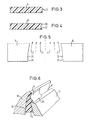
- FIG. 3 is a schematic Longitudinal sectional view of a format slide 16 along the Line I-I in Fig. 2 shows that to a central portion of the metering gap 8 facing inner surface 20 of the Format slide 16 in the embodiment of FIGS. 1 and 2 designed as a simple flat and smooth surface.
- FIG. 4 is analogous to FIG. 3 A schematic longitudinal sectional view of a second embodiment of a format slider 16 of Applicator work shown.
- the inside surface 20 of the format slide has one trough-like indentation 22, which the leadership effect of Inside surface 20 increased.
- Fig. 5 shows a schematic frontal view of a third Embodiment of a format slider 16, analogous to that 2, but the complete Inlet and outlet lip of clarity were omitted for the sake of it.
- a format slider 16 analogous to that 2, but the complete Inlet and outlet lip of clarity were omitted for the sake of it.
- the central portion of the metering gap 8 facing inner side surfaces 20 of the format slider 16, 18th an arcuate edge course 24 so that the Inner side surfaces 20 of the opposite one another Format slider 16 have a converging arrangement.
- the inner side surfaces 20 of the Format slider 16 flowing liquid or pasty Coating medium 2 additionally one inwards, that is in Direction towards a central section of the concave guide surface 14 directed impulse, which is an adverse lateral Flowing out or spraying out of the coating medium 2 additionally counteracts.
- the middle section of the concave Guide surface 14 is shown in the drawing by a vertical Line of symmetry represented. Instead of an arched one Edge course 24 is of course a straight line, however sloping edge course possible, which also to the previous described converging configuration leads.
- Fig. 6 shows a schematic perspective view of a fourth embodiment of the format slider, in which the concavely curved wall section 18 based on its Cross-sectional shape in the area of the concave guide surface 14 a step-like paragraph 26 widened on the Top of the drain lip 12 rests.
- the step-like paragraph 26 can be used, for example, as a guide element serve when moving the format slider 16.
- FIG. 7 shows an analogous to the representation in FIG. 1 schematic cross-sectional representation of a fifth Embodiment of the application unit according to the invention.
- This Variant essentially corresponds to its basic structure 1, 1a, however, has the longer inlet side Lip 10 has a straight guide surface 14 and the one in it Cross-sectional design according to adapted format slider 16 are - in the flow direction of the coating medium 2 in Dosing gap seen - in an area in front of or below the Exit of the metering gap 8 each with a recess 30 to accommodate one with a variety of defined Passage columns 28.2 provided profile strip 28 fitted.
- the cutouts 30 and the profile strip 28 can also be seen particularly clearly in FIG is a schematic sectional view of FIG. 7 in the area of Dosing gap 8 and the profile strip 28 shows.
Abstract
Description
Die vorliegende Erfindung betrifft ein Auftragwerk zum direkten oder indirekten Auftragen eines flüssigen oder pastösen Streichmediums auf eine laufende Materialbahn, insbesondere aus Papier oder Karton.The present invention relates to a commissioned work for direct or indirect application of a liquid or pasty coating medium on a running material web, in particular made of paper or cardboard.
Gattungsgemäße Auftragwerke werden im Rahmen von sogenannten Streichanlagen eingesetzt, um eine laufende Materialbahn, die beispielsweise aus Papier, Karton oder einem Textilwerkstoff besteht, ein- oder beidseitig mit einer oder mehreren Schichten des Streichmediums, beispielsweise Farbe, Stärke, Imprägnierflüssigkeit oder dergleichen, zu versehen.Generic commissioned works are part of so-called Coating lines used to make a running web of material for example made of paper, cardboard or a textile material exists, on one or both sides with one or more Layers of the coating medium, for example color, thickness, Impregnation liquid or the like.
Beim sogenannten direkten Auftrag wird das flüssige oder pastöse Streichmedium von einer Auftragseinrichtung direkt auf die Oberfläche der laufenden Materialbahn aufgetragen, die während des Auftrags auf einer umlaufenden Gegenfläche, beispielsweise einem Endlosband oder einer Gegenwalze, gestützt wird. Beim indirekten Auftrag des Mediums wird das flüssige oder pastöse Streichmedium hingegen zunächst auf eine Trägerfläche, z.B. die Oberfläche einer als Auftragwalze ausgestalteten Gegenwalze, aufgebracht, um von dort in einem Walzenspalt, durch den die Materialbahn hindurchläuft, von der Auftragwalze auf die Materialbahn übertragen zu werden.With the so-called direct application, the liquid or pasty coating medium directly from an application device applied to the surface of the running material web, that during the order on a rotating counter surface, for example an endless belt or a counter roller, is supported. When the medium is applied indirectly, this becomes liquid or pasty coating medium, however, initially a support surface, e.g. the surface of one as an applicator roller designed counter roll, applied to from there in one Nip through which the material web runs from the application roller to be transferred to the material web.
Aus der US-A-5, 435, 847 ist ein Auftragwerk bekannt, mit einer Auftrageinrichtung, die einen zwischen zwei einander gegenüberliegenden Wänden gebildeten Spalt von konstanter Breite aufweist, durch den das aufzutragenden Streichmedium unter Druck auf eine Materialbahn geleitet wird, die üblicherweise von einer der Auftrageinrichtung zugeordneten Gegenwalze gestützt ist. Dieses Auftragwerk umfaßt des weiteren eine Streichrandbegrenzungseinrichtung mit zwei Streichrandbegrenzungselementen in der Gestalt von Formatschiebern, die zwischen den einander gegenüberliegenden Wänden im Spalt angeordnet sind und diesen an seinen Seitenrändern abdichtend verschließen. Die Formatschieber sind an die konstante Breite des Spaltes angepaßt und weisen eine im wesentlichen rechteckige Querschnittsform auf. Des weiteren ist ein jeweiliger Formatschieber zur Einstellung der Strichbreite auf der laufenden Materialbahn in einer quer zur laufenden Materialbahn liegenden Richtung im Spalt verschiebbar und fixierbar und verbleibt während des laufenden Betriebs des Auftragwerks in der einmal eingestellten Position. Bei diesem bekannten Auftragwerk treten Nachteile dahingehend auf, daß das flüssige oder pastöse Streichmedium in Abhängigkeit von bestimmten Auftrags- oder Streichbedingungen beim Austritt aus dem Spalt oftmals seitlich ausströmt oder herausspritzt, was auf der beschichteten Materialbahn zu einem unsauberen Rand beziehungsweise Randverlauf und damit zu einer Beeinträchtigung der Qualität des gefertigten Produktes führt. From US-A-5, 435, 847 an application is known, with a Application device, the one between two each other opposite walls formed gap of constant Has width through which the coating medium to be applied is passed under pressure onto a material web which usually from one assigned to the application device Counter roll is supported. This commission includes the further a streak border device with two Streak border elements in the shape of Format sliders that are between the opposite Walls are arranged in the gap and this on his Seal the side edges with a seal. The format slider are adapted to the constant width of the gap and have has a substantially rectangular cross-sectional shape. Of another is a format slider for adjustment the line width on the running material web in a cross to the running material web in the gap slidable and fixable and remains during the ongoing operation of the commissioning plant in the once set position. With this well-known commission Disadvantages occur in that the liquid or pasty coating medium depending on certain Application or deletion conditions when leaving the gap often flows out of the side or squirts out what's on the coated material web to an unclean edge or edge course and thus to one Impairment of the quality of the manufactured product leads.
Des weiteren ist aus der US-A-5, 436, 030 ein Auftragwerk zum direkten oder indirekten Auftragen eines flüssigen oder pastösen Streichmediums auf eine laufende Materialbahn, insbesondere aus Papier oder Karton, bekannt, das eine Dosiereinrichtung mit einem als Freistrahldüse ausgebildeten Dosierspalt umfaßt, der zwischen einer zulaufseitigen und einer ablaufseitigen Lippe gebildet ist, wobei in einer Ausführungsform an dem freien Ende der zulaufseitigen oder ablaufseitigen Lippe eine sich an den Dosierspalt anschließende konkav gekrümmte Umlenkfläche für das flüssige oder pastöse Streichmedium angeordnet ist. Diejenige Lippe der beiden den Dosierspalt bildenden Lippen, die auf der Seite des Dosierspalts liegt, auf der beim indirekten Auftrag des Mediums die Auftragwalze bzw. beim direkten Auftrag des Mediums die Materialbahn auf das Auftragwerk zuläuft, wird als zulaufseitige Lippe bezeichnet. Entsprechend wird die zweite Lippe, die auf der Seite des Dosierspalts liegt, auf der die Auftragwalze bzw. die Materialbahn vom Auftragwerk wegläuft, als ablaufseitige Lippe bezeichnet. Bei einem Einsatz einer sich an den Dosierspalt anschließenden konkav gekrümmten Umlenkfläche für das flüssige oder pastöse Streichmedium hat es sich herausgestellt, daß sich in Abhängigkeit von bestimmten Streichbedingungen beziehungsweise dem jeweils verwendeten flüssigen oder pastösen Streichmedium sogenannte "Farbsegel", das heißt ein sich aus an dem Seitenrand des Ausgangs des Dosierspalts bildenden Nasen des Streichmediums ziehender dünner Film, an der konkaven Umlenkfläche bilden können, die unter Umständen zu einem unsauberen Streichrand führen.Furthermore, from US-A-5, 436, 030 an application for direct or indirect application of a liquid or pasty coating medium on a running material web, especially known from paper or cardboard, the one Dosing device with a free jet nozzle Dosing gap includes that between an inlet and a drain-side lip is formed, wherein in a Embodiment at the free end of the inlet side or lip on the outlet side adjusts itself to the metering gap subsequent concave curved deflection surface for the liquid or pasty coating medium is arranged. That lip of the two lips forming the metering gap, which on the Side of the metering gap is on the indirect application of the medium the application roller or in the direct application of the Medium, the material web runs towards the application referred to as the inlet lip. Accordingly, the second lip on the side of the metering gap the application roller or the material web from the application unit runs away, referred to as the drain-side lip. At a Use of a concave adjoining the metering gap curved deflection surface for the liquid or pasty Coating medium, it has been found that in Dependence on certain coating conditions or the respectively used liquid or pasty coating medium so-called "color sail", that is, a out on the side edge of the exit of the metering gap thin film forming noses of the coating medium the concave deflection surface can form, which may lead to a dirty streak.
Ein mit dem Auftragwerk gemäß der US-A-5,436,030 vergleichbares Auftragwerk wird auch von der Anmelderin unter der Handelsbezeichnung "Jet Flow F" vertrieben. One with the applicator according to US-A-5,436,030 Comparable commissioned work is also under by the applicant sold under the trade name "Jet Flow F".
Der vorliegenden Erfindung liegt daher die Aufgabe zugrunde ein gattungsgemäßes Auftragwerk, das heißt ein Auftragwerk in der Art des zuvor beschriebenen "Jet Flow F", derart weiterzubilden, daß auch unter unterschiedlichsten Streichbedingungen ein qualitativ hochwertiger Auftrag mit sauberen Streichrändern erzielt wird.The present invention is therefore based on the object a generic commission, that is a commission in the type of "Jet Flow F" described above, such to train that even under the most varied Coating conditions with a high quality order clean streak marks is achieved.
Diese Aufgabe wird gelöst durch ein erstes erfindungsgemäßes Auftragswerk mit den Merkmalen des Anspruchs 1, sowie ein zweites Auftragswerk mit den Merkmalen des Anspruches 2.This object is achieved by a first invention Commissioned work with the features of claim 1, and a second Commissioned work with the features of claim 2.
Dieses erste erfindungsgemäße Auftragswerk zum direkten oder indirekten Auftragen eines flüssigen oder pastösen Streichmediums auf eine laufende Materialbahn, insbesondere aus Papier oder Karton, umfaßt wenigstens eine Dosiereinrichtung mit einem als Freistrahldüse ausgebildeten Dosierspalt, der zwischen zwei Lippen gebildet ist, von denen in Strömungsrichtung des Streichmediums gesehen eine länger als die andere ist und eine Leitfläche für das Streichmedium bildet, sowie eine Streichrandbegrenzungseinrichtung mit wenigstens zwei Streichrandbegrenzungselementen, die zwischen den beiden Lippen angeordnet sind und den Dosierspalt an dessen Seitenrändern im wesentlichen abdichtend verschließen, wobei sich bei Betrachtung eines Streichrandbegrenzungselementes im Querschnitt an dessen dem Ausgang des Dosierspalts zugeordneten Ende ein Wandungsabschnitt anschließt, welcher sich entlang der Leitfläche der längeren der beiden Lippen im wesentlichen bis zu dem freien Ende der längeren Lippe erstreckt.This first commissioned work according to the invention for direct or indirect application of a liquid or pasty Coating medium on a running material web, in particular of paper or cardboard, comprises at least one Dosing device with a free jet nozzle Dosing gap that is formed between two lips, one of which seen in the direction of flow of the coating medium a longer than the other and is a guide surface for the coating medium forms, as well as a streak border limiting device at least two delimitation elements between the two lips are arranged and the metering gap seal the side edges essentially sealing, considering one Cross-border element in cross-section at its Output of the metering gap associated end Connects wall section, which extends along the Guide surface of the longer of the two lips essentially up extends to the free end of the longer lip.
Ein erfindungsgemäßes Streichrandbegrenzungselement, dessen jeweilige Querschnittsgestaltung vorzugsweise der Querschnittsform des Dosierspaltes angepaßt ist, ragt also mit dem besagten Wandungsabschnitt durch den Dosierspalt hindurch, während sich die verbleibenden Abschnitte des Streichrandbegrenzungselements in einem unterhalb des Dosierspaltausgangs liegenden Randbereich zwischen den beiden Lippen im Dosierspalt erstrecken. Die genaue Form des Wandungsabschnitts eines Streichrandbegrenzungselementes ist der Form der Leitfläche der längeren Lippe angepaßt, so daß der besagte Wandungsabschnitt des Streichrandbegrenzungselementes bündig und ohne Zwischenraum flächig an der Leitfläche anliegt. Der obere Rand des Wandungsabschnitts eines Streichrandbegrenzungselementes endet vorzugsweise an dem freien Oberrand der Leitfläche der längeren der beiden Lippen, oder etwas unterhalb davon. Bei dem erfindungsgemäßen Auftragwerk können die beiden Lippen, zwischen denen der Dosierspalt gebildet ist, zur Einstellung der Spaltbreite des Dosierspaltes relativ zueinander beweglich sein. Des weiteren kann die Leitfläche der längeren der beiden Lippen zur Einstellung des Auftreffwinkels des an der Leitfläche entlangströmenden Streichmediums verstellbar ausgebildet sein, etwa durch eine im Bereich des Ausgangs des Dosierspaltes vorgesehene Schwenkachse oder dergleichen.A streak boundary element according to the invention, the respective cross-sectional design, preferably the Cross-sectional shape of the metering gap is adapted, so protrudes with said wall section through the metering gap through while the remaining sections of the Scraper border element in a below the Dosing gap output edge area between the two Extend lips in the metering gap. The exact shape of the Wall portion of a streak border element adapted to the shape of the guide surface of the longer lip, so that said wall section of the Scraper border element flush and without space lies flat against the guide surface. The top of the Wall section of a streak boundary element preferably ends at the free upper edge of the guide surface longer of the two lips, or slightly below it. At the lips according to the invention, between which the metering gap is formed for adjustment the gap width of the metering gap relative to each other be agile. Furthermore, the guide surface of the longer one of the two lips to adjust the angle of incidence of the adjustable coating medium flowing along the guide surface be formed, for example by a in the area of the exit of the Dosing gap provided pivot axis or the like.
Das erfindungsgemäße Auftragwerk vermeidet auf vorteilhafte Art und Weise die dem Stand der Technik anhaftenden Nachteile und ermöglicht auch bei unterschiedlichsten Streichbedingungen und der Verwendung von unterschiedlichen Streichmediumtypen einen qualitativ hochwertigen Auftrag mit sauberen Rändern und einer scharfen Trennung zwischen einem gestrichenen und ungestrichenen Abschnitt der Materialbahn beziehungsweise der Auftragwalze. Aufgrund der erfindungsgemäß ausgestalteten Streichrandbegrenzungselemente mit einem Wandungsabschnitt, der sich von dem Ausgang des Dosierspaltes bis vorzugsweise direkt an das obere freie Ende der Leitfläche der längeren Lippe erstreckt, wird dem aus dem Dosierspalt austretenden flüssigen oder pastösen Streichmedium an den Seitenrändern des Dosierspaltes und darüber hinaus eine durch die zum Dosierspalt weisende Innenseitenfläche des Streichrandbegrenzungselementes gebildete zusätzliche seitliche Führungsfläche zur Verfügung gestellt, an der das Streichmedium entlangströmt bis es die Dosiereinrichtung an dem oberen freien Ende der Leitfläche und unmittelbar vor der zu beschichtenden Fläche verläßt. Ein seitliches Ausströmen oder Herausspritzen des aus dem Dosierspalt austretenden Streichmediums wird somit auf einfache und effektive Weise vermieden.The application mechanism according to the invention avoids advantageous Way the disadvantages inherent in the prior art and enables even the most diverse Coating conditions and the use of different Coating medium types with a high quality order clean edges and a sharp separation between one painted and uncoated section of the material web or the application roller. Due to the Stroke boundary elements designed according to the invention with a wall section that extends from the exit of the Dosing gap until preferably directly to the upper free end the leading surface of the longer lip extends from the Dosing gap emerging liquid or pasty Coating medium on the side edges of the metering gap and moreover one through the one facing the metering gap Inner side surface of the coating edge delimiting element formed additional side guide surface available along which the coating medium flows until it reaches the Dosing device at the upper free end of the guide surface and leaves immediately in front of the surface to be coated. On lateral discharge or splashing out of the Dosing gap emerging coating medium is thus on avoided simple and effective way.
Ein vorteilhaftes Ausgestaltungsmerkmal der Erfindung sieht vor, daß sich das obere Ende des Wandungsabschnitts des Streichrandbegrenzungselementes in Strömungsrichtung des Streichmediums gesehen über das freie Ende der längeren Lippe hinaus erstreckt. Somit wird dem Streichmedium sogar nach Verlassen der Leitfläche der längeren der beiden Lippen eine seitliche Führungsfläche bereitgestellt, welche die Herstellung eines scharfen, sauberen Streichrands gestattet.An advantageous feature of the invention provides before that the upper end of the wall portion of the Streichrandbegrenzungselementes in the direction of flow Coating medium seen over the free end of the longer lip extends beyond. Thus, the coating medium is even after Leaving the guiding surface of the longer of the two lips lateral guide surface provided which the Permitted to produce a sharp, clean streak.
Die Leitfläche der längeren Lippe ist vorzugsweise im wesentlichen gerade oder konkav oder konvex geformt ist. Grundsätzlich sind auch entsprechende Mischformen denkbar.The guide surface of the longer lip is preferably in is essentially straight or concave or convex. Appropriate mixed forms are also conceivable in principle.
Ein anderes vorteilhaftes Ausgestaltungsmerkmal der Erfindung sieht vor, daß der Wandungsabschnitt eines Streichrandbegrenzungselementes im Bereich der Leitfläche eine im wesentlichen konstante Wandstärke besitzt. Somit kann sich der besagte Wandungsabschnitt besonders gut an die jeweilige Form der Leitfläche der längeren Lippe anpassen. Entspricht die Wandstärke des Wandungsabschnitts des Streichrandbegrenzungselements der Dosierspaltbreite, kann das Streichrandbegrenzungselement aufgrund dieser Dimensionierung auch leicht nach unten durch den Dosierspalt herausgezogen und entfernt bzw. ausgewechselt werden. Die Erfindung ist jedoch selbstverständlich nicht auf diese Ausführungsform beschränkt.Another advantageous design feature of the invention provides that the wall section of a Stroke boundary element in the area of the guide surface has a substantially constant wall thickness. So can said wall section looks particularly good on the Adapt the respective shape of the guide surface to the longer lip. Corresponds to the wall thickness of the wall section of the Scraper border limiting element of the metering gap width, can the streak border element due to this Dimensioning also slightly downwards through the metering gap pulled out and removed or replaced. The However, invention is of course not based on this Embodiment limited.
Gemäß einer anderen günstigen Ausführungsvariante des erfindungsgemäßen Auftragwerks besitzt ein Streichrandbegrenzungselement eine zu einem Mittelabschnitt des Dosierspalts weisende, im wesentlichen plane Innenseitenfläche, die, wie oben erläutert, als seitliche Führungsfläche für das flüssige oder pastöse Streichmedium dient. Ein derartiges Streichrandbegrenzungselement ist besonders einfach herzustellen und erzielt bei den meisten Anwendungen die zuvor geschilderten Vorteile.According to another cheap variant of the Applicator according to the invention has a Stroke boundary element one to a middle section of the metering gap, essentially plane Inside surface, which, as explained above, as a side Guide surface for the liquid or pasty coating medium serves. Such a delimitation element is particularly easy to manufacture and achieved with most Applications the advantages described above.
Für bestimmte Anwendungsfälle hat es sich indes als von Vorteil erwiesen, daß ein Streichrandbegrenzungselement eine zu einem Mittelabschnitt des Dosierspalts weisende rinnenartige Innenseitenfläche besitzt. Auf diese Weise kann die Führungswirkung der Innenseitenfläche weiter gesteigert werden, was auch bei problematischeren Streichmedien zu guten Ergebnissen führt.For certain applications, however, it has turned out to be Proved advantage that a streak border element towards a central section of the metering gap has groove-like inside surface. That way the leadership effect of the inside surface further increased become, which is also good for more problematic coating media Results.
In der einfachsten Ausführungsform sind die einander gegenüberliegenden Streichrandbegrenzungselemente vorzugsweise derart zueinander ausgerichtet, daß ihre zu dem Mittelabschnitt des Dosierspalts weisenden Innenseitenflächen im wesentlichen parallel zueinander verlaufen. Eine andere vorteilhafte erfindungsgemäße Variante sieht hingegen vor, daß die zu dem Mittelabschnitt des Dosierspalts weisende Innenseitenfläche eines Streichrandbegrenzungselementes bei Betrachtung des Streichrandbegrenzungselementes in einer Frontalansicht einen bogenförmigen Randverlauf besitzt, so daß die Innenseitenflächen der einander gegenüberliegenden Streichrandbegrenzungselemente eine konvergierende Anordnung aufweisen. Somit erhält das an den Innenseitenflächen der Streichrandbegrenzungselemente entlangströmende flüssige oder pastöse Medium zusätzlich einen nach innen, das heißt in Richtung auf einen Mittelabschnitt der Leitfläche gerichteten Impuls, der einem nachteiligen seitlichen Ausströmen oder Herausspritzen des Streichmediums zusätzlich entgegenwirkt. Anstelle eines bogenförmigen Randverlaufs ist natürlich auch ein geradliniger, jedoch schräger Randverlauf möglich, der ebenfalls zu der zuvor beschriebenen konvergierenden Konfiguration führt.In the simplest embodiment, they are each other opposite streak border elements preferably aligned with each other so that their to the Middle section of the metering gap facing inner side surfaces run essentially parallel to each other. Another advantageous variant according to the invention, however, provides that facing the central portion of the metering gap Inner side surface of a coating border delimitation element Consideration of the border delimitation element in one Frontal view has an arcuate course, so that the inside faces of the opposing Stroke boundary elements a converging arrangement exhibit. This gives the inside of the Stroke boundary elements flowing along liquid or pasty medium additionally one inside, that is, in Direction towards a central portion of the guide surface Impulse causing an adverse side leak or Spraying out the coating medium also counteracts. Instead of an arched edge course is of course also a straight, but sloping edge course possible, the also converging to that previously described Configuration leads.
In wenigstens einer bevorzugten Ausführungsform der Erfindung ist mindestens ein Streichrandbegrenzungselement mit einer Aussparung zur Aufnahme einer mit einer Vielzahl von definierten Durchtrittsspalten versehenen Profilleiste ausgestattet, wie sie aus der am 13.03.1997 veröffentlichten DE-A-19 532 920 der Anmelderin bekannt ist. Diese Aussparung ist bezogen auf die Strömungsrichtung des flüssigen oder pastösen Streichmediums vorzugsweise vor dem Ausgang des Dosierspaltes in dem Streichrandbegrenzungselement vorgesehen. Somit können die erfindungsgemäßen Streichrandbegrenzungselemente auch in Verbindung mit einer Profilleiste der genannten Art eingesetzt werden.In at least one preferred embodiment of the invention is at least one delimiter with a Recess to accommodate a variety of defined profile columns provided passage columns equipped, as from DE-A-19 532 920 published on 13.03.1997 is known to the applicant. This recess is related to the direction of flow of the liquid or pasty Coating medium preferably before the exit of the metering gap provided in the streak border element. So you can the streak border elements according to the invention also in Connection with a profile bar of the type mentioned be used.
Die Streichrandbegrenzungselemente des erfindungsgemäßen Auftragwerks sind bevorzugt aus einem Kunststoffmaterial hergestellt, im Gegensatz zu konventionellen Streichrandbegrenzungselementen, die üblicherweise aus Metall, wie etwa Bronze, gefertigt sind.The streak border elements of the invention Applicator are preferably made of a plastic material manufactured, in contrast to conventional Streak border elements that are usually made up of Metal, such as bronze.
In einer weiteren vorteilhaften Ausführungsform der Erfindung sind die Streichrandbegrenzungselemente im wesentlichen parallel zur Längserstreckung des Dosierspaltes, d.h. also quer zur Laufrichtung der Materialbahn, beweglich angeordnet. Dies gestattet eine einfache Einstellung des jeweils erforderlichen Strichformates. Die Einstellung kann hierbei stufenlos oder schrittweise erfolgen. Zweckmäßigerweise sind die Streichrandbegrenzungselemente in einer gewählten Formatposition fixierbar.In a further advantageous embodiment of the invention the streak border elements are essentially parallel to the longitudinal extent of the metering gap, i.e. so arranged transversely to the direction of travel of the material web, movable. This allows easy adjustment of each required line format. The setting can can be done continuously or gradually. Are expedient the delimiter elements in a selected one Format position fixable.
Schließlich ist gemäß einem besonders vorteilhaften Ausgestaltungsmerkmal der Erfindung vorgesehen, daß die Streichrandbegrenzungselemente im wesentlichen parallel zur Längserstreckung des Dosierspaltes schrittweise und/oder oszillierend beweglich angeordnet sind. Das Auftragwerk umfaßt in diesem Zusammenhang zweckmäßigerweise mindestens eine mit den Streichrandbegrenzungselementen verbundene Antriebseinrichtung, welche die Streichrandbegrenzungselemente schrittweise und/oder oszillierend antreibt und/oder bei Bedarf zur Einstellung der gewünschten Strichbreite bewegt. Die Bewegung kann grundsätzlich auch manuell erfolgen. Des weiteren kann das Auftragwerk wenigstens eine mit der Antriebseinrichtung korrespondierende Kontroll- und/oder Regeleinrichtung aufweisen. Diese bewegliche Anordnung der Streichrandbegrenzungselemente gestattet auf einfache und effektive Art und Weise eine beträchtliche Reduzierung und Vergleichmäßigung des örtlichen Verschleißes eines Rakelelements, wie es üblicherweise bei Auftragwerken der gattungsgemäßen zum Abrakeln des Auftrags eingesetzt wird, an den Übergangsstellen zwischen dem gestrichenen und ungestrichenen Rand und damit eine Erhöhung der Standzeit des Rakelelements. Dies ermöglicht gegenüber dem bekannten Stand der Technik längere Wartungsintervalle bis zum erforderlichen Austauschen des Rakelelements, wodurch wiederum längere Stillstandszeiten des Auftragwerks vermieden und geringere Gesamtbetriebskosten erzielt werden. Da bei dem erfindungsgemäßen Auftragwerk keine ausgeprägte örtliche Verschleißstelle an dem Rakelelement auftritt, ist das Rakelelement für eine gegenüber einer ursprünglichen Einstellung geänderte Formateinstellung, d.h. Strichbreite, verwendbar, ohne daß ein Austauschen des Rakelelements notwendig ist oder eine Qualitätsminderung des gefertigten Produktes eintritt. Auch kann in dem Fall, in dem die Übergangsstellen zwischen dem gestrichenen und ungestrichenen Rand nicht auf der Auftrag- oder Gegenwalze sondern auf der Materialbahn selbst liegen, ein abrupter Dickenunterschied zwischen einem gestrichenen und ungestrichenen Abschnitt der Materialbahn wirksam vermieden werden. Das erfindungsgemäße Auftragwerk schafft vielmehr einen weichen oder "verwischten" Übergang zwischen dem gestrichenen und ungestrichenen Abschnitt der Materialbahn, was auch das Aufrollen, Abrollen oder Umrollen der Materialbahn sowie die Handhabung des fertigen Erzeugnisses erheblich erleichtert.Finally, according to a particularly advantageous Design feature of the invention provided that the Streichrandbegrenzungselemente essentially parallel to Longitudinal extension of the metering gap gradually and / or are arranged to oscillate and move. The commissioned work expediently includes at least in this context one connected to the streak border elements Drive device which the Graduated border elements and / or drives oscillating and / or if necessary to adjust the desired stroke width moves. The movement can always done manually. Furthermore, it can Application unit at least one with the drive device corresponding control and / or regulating device exhibit. This movable arrangement of the Stroke boundary elements allowed on simple and effective way a significant reduction and Uniformization of local wear and tear Doctor element, as is usually the case with applicators is used for doctoring the order the transition points between the deleted and uncoated edge and thus an increase in the service life of the Doctor element. This enables compared to the known state the technology longer maintenance intervals until the required Replacing the doctor element, which in turn longer Downtimes of the application unit avoided and less Total cost of ownership can be achieved. Because with that Application work according to the invention is not a distinct local one Wear point occurs on the doctor element, that is Doctor element for one versus an original Setting changed format setting, i.e. Line width, usable without replacing the doctor element is necessary or a reduction in quality of the manufactured Product occurs. Also, in the event that the Transition points between the deleted and uncoated Edge not on the application or counter roller but on the Material web itself, an abrupt difference in thickness between a painted and an uncoated section of the Material web can be avoided effectively. The invention Rather, commissioned work creates a soft or "blurred" Transition between the deleted and uncoated Section of the material web, which is also the rolling up, unrolling or rewinding the material web and handling the finished product considerably easier.
Beim zweiten erfindungsgemäßen Auftragswerk enden die beiden Lippen vorzugsweise in annähernd gleicher Höhe. Wenigstens ein Streichrandbegrenzungselement erstreckt sich hierbei über die freien Enden beider Lippen hinaus, wodurch eine noch bessere Abdichtwirkung erzielbar ist. Eine Erläuterung der zweckmäßigen Ausgestaltung der zweiten Erfindung soll hier nicht erfolgen, da diese Ausgestaltungsmöglichkeiten im wesentlichen jenen der ersten Erfindung entsprechen. In the second application work according to the invention, the two lips preferably end at approximately the same height. At least one border delimiter extends over the free ends of both lips addition, whereby an even better sealing effect can be achieved. An explanation of the practical embodiment of the second invention should not be done here because these design options in correspond essentially to those of the first invention.
Bevorzugte Ausführungsbeispiele der Erfindung mit zusätzlichen Ausgestaltsdetails und weiteren Vorteilen sind nachfolgend unter Bezugnahme auf die beigefügten Zeichnungen näher beschrieben und erläutert. Es zeigt:
- Fig. 1
- eine schematische Querschnittsdarstellung einer bevorzugten Ausführungsform des ersten erfindungsgemäßen Auftragwerks im Bereich der Dosiereinrichtung,
- Fig. 1a
- eine schematische Querschnittsdarstellung einer bevorzugten Ausführungsform des zweiten erfindungsgemäßen Auftragwerks im Bereich der Dosiereinrichtung,
- Fig. 2
- eine schematische Frontalansicht des Auftragwerks von Fig. 1 im Bereich eines Streichrandbegrenzungselementes, in Blickrichtung des Pfeils X in Fig. 1,
- Fig. 3
- eine schematische Längsschnittansicht eines Streichrandbegrenzungselementes entlang der Linie I-I in Fig. 2,
- Fig. 4
- eine schematische Längsschnittansicht einer zweiten Ausführungsform eines Streichrandbegrenzungselementes, analog zu der Darstellungsweise in Fig. 3,
- Fig. 5
- eine schematische Frontalansicht einer dritten Ausführungsform von Streichrandbegrenzungselementen, analog zu der Darstellungsweise in Fig. 2,
- Fig. 6
- eine schematische Perspektivansicht einer vierten Ausführungsform eines Streichrandbegrenzungselementes,
- Fig. 7
- eine schematische Querschnittsdarstellung einer fünften Ausführungsform des erfindungsgemäßen Auftragwerks, analog zu der Darstellungsweise in Fig. 1, und
- Fig. 8
- eine schematische Schnittansicht der Fig. 7 im Bereich des Dosierspaltes.
- Fig. 1
- 2 shows a schematic cross-sectional representation of a preferred embodiment of the first application unit according to the invention in the area of the metering device,
- Fig. 1a
- 2 shows a schematic cross-sectional representation of a preferred embodiment of the second application unit according to the invention in the area of the metering device,
- Fig. 2
- 2 shows a schematic frontal view of the applicator unit from FIG. 1 in the area of a coating boundary element, in the direction of the arrow X in FIG. 1,
- Fig. 3
- 2 shows a schematic longitudinal sectional view of a coating edge delimiting element along the line II in FIG. 2,
- Fig. 4
- 2 shows a schematic longitudinal sectional view of a second embodiment of a coating edge delimitation element, analogous to the representation in FIG. 3,
- Fig. 5
- 2 shows a schematic frontal view of a third embodiment of streak border elements, analogous to the representation in FIG. 2,
- Fig. 6
- 2 shows a schematic perspective view of a fourth embodiment of a coating edge delimiting element,
- Fig. 7
- is a schematic cross-sectional view of a fifth embodiment of the application unit according to the invention, analogous to the representation in Fig. 1, and
- Fig. 8
- is a schematic sectional view of FIG. 7 in the region of the metering gap.
In der nachfolgenden Beschreibung und in den Figuren werden zur Vermeidung von Wiederholungen gleiche Bauteile und Komponenten auch mit gleichen Bezugszeichen gekennzeichnet, sofern keine weitere Differenzierung erforderlich ist.In the description below and in the figures To avoid repetitions, the same components and Components also identified with the same reference symbols, unless further differentiation is required.
Der Fig. 1 ist in einer schematischen Querschnittsdarstellung
eine bevorzugte Ausführungsform des erfindungsgemäßen
Auftragwerks zum direkten oder indirekten Auftragen eines
flüssigen oder pastösen Streichmediums 2 auf eine laufende
Materialbahn 4, insbesondere aus Papier oder Karton, im
Bereich der Auftrag- bzw. Dosiereinrichtung zu entnehmen. Das
Auftragwerk umfaßt eine Gegenwalze 6, auf der eine mit dem
flüssigen oder pastösen Streichmedium 2 zu versehene
Materialbahn 4 läuft und während des Auftragsvorgangs von der Gegenwalze
6 gestützt wird. Die Laufrichtung der Materialbahn 4 ist durch die in der
Figur mit einem Pfeil angedeutete Drehrichtung der Gegenwalze 6 vorgegeben.
Die Dosiereinrichtung, die sich im wesentlichen quer über die gesamte
Maschinenbreite und die laufende Materialbahn 4 erstreckt, liegt der
Gegenwalze 6 gegenüber. Der Dosiereinrichtung ist in Laufrichtung der
Materialbahn 4 ein sich über die gesamte Maschinenbreite erstreckendes
Rakelement, etwa eine Rakelklinge oder dergleichen, nachgeschaltet, das
überschüssiges aufgetragenes Streichmedium 2 auf ein geeignetes Profil
abrakelt. Das Rakelelement ist in der Zeichnung deshalb nicht gezeigt,
weil es auch weggelassen werden kann, wenn beispielsweise nur soviel
Streichmedium aufgetragen wird, wie auf der Warenbahn verbleiben soll.
Die Dosiereinrichtung umfaßt einen als Freistrahldüse
ausgebildeten Dosierspalt 8, der zwischen zwei Lippen 10, 12,
nämlich einer zulaufseitigen 10 und einer ablaufseitigen
Lippe 12, gebildet ist. In Strömungsrichtung des
Streichmediums 2 im Dosierspalt gesehen ist im vorliegenden
Fall die zulaufseitige Lippe 10 länger als die ablaufseitige
Lippe 12 ausgestaltet und bildet in dem sich an den Ausgang
des Dosierspalts anschließenden Bereich eine Leitfläche 14
für das flüssige oder pastöse Streichmedium 2. Diese
Leitfläche 14 ist bei dem vorliegenden Ausführungsbeispiel
konkav geformt. Die zulaufseitige 10 und die ablaufseitige
Lippe 12 können zur Einstellung der Spaltbreite des
Dosierspaltes 8 relativ zueinander beweglich sein. Des
weiteren ist die konkave Leitfläche 14 zur Einstellung des
Auftreffwinkels des an der Leitfläche 14 entlangströmenden
Streichmediums 2 zusammen mit der zulaufseitigen Lippe 10
verstellbar ausgebildet. Dies ist hier durch eine im Bereich
unterhalb des Dosierspaltausgangs an der zulaufseitigen Lippe
10 vorgesehene örtliche Dünnstelle 10.2, die eine
Schwenkachse bildet, realisiert. Die Stellglieder zur
Verstellung der zulaufseitigen Lippe 10 sind in der Zeichnung
der Übersichtlichkeit halber nicht dargestellt.1 is a schematic cross-sectional representation
a preferred embodiment of the invention
Applicator for direct or indirect application of a
liquid or pasty coating medium 2 on a running
Material web 4, in particular made of paper or cardboard, in
Take the area of the application or dosing device. The
Applicator comprises a counter roller 6, on which one with the
liquid or pasty coating medium 2 to be provided
Material web 4 runs and during the application process from the counter roller
6 is supported. The running direction of the material web 4 is by the in the
Figure with an arrow indicated direction of rotation of the counter roller 6 predetermined.
The metering device, which is essentially across the entire
Machine width and the running material web 4 extends, is the
Counter roll 6 opposite. The metering device is in the direction of rotation
Material web 4 extends over the entire machine width
Rak element, such as a doctor blade or the like, downstream, that
excess applied coating medium 2 on a suitable profile
scrapes off. The doctor element is therefore not shown in the drawing,
because it can also be omitted if, for example, only so much
Coating medium is applied as is to remain on the web.
The metering device comprises a free jet nozzle
formed
Das Auftragwerk umfaßt ferner eine der Dosiereinrichtung
zugeordnete Streichrandbegrenzungseinrichtung mit zwei aus
Kunststoff hergestellten Streichrandbegrenzungselementen, im
nachfolgenden Formatschieber 16 genannt, die zwischen der
zulaufseitigen 10 und der ablaufseitigen Lippe 12 angeordnet
sind. Die Formatschieber 16 verschließen den Dosierspalt 8
abdichtend an dessen beiden Seitenrändern und geben somit
eine bestimmte Strichbreite auf der laufenden Materialbahn 4
vor. Wie in der Fig. 1 zu erkennen, besitzen die
Formatschieber 16 eine der Querschnittsform des Dosierspaltes
8 angepaßte Querschnittgestaltung. Im vorliegenden Fall
weisen die Formatschieber 16 eine konische Querschnitts-Grundform
auf, die sich im wesentlichen stetig nach oben, das
heißt zum Ausgang des Dosierspaltes 8 hin, verjüngt.
Prinzipiell können die Formatschieber 16 natürlich auch eine
andere geeignete Querschnittsform aufweisen, etwa eine
einfache rechteckige Querschnittsform.The applicator also includes one of the metering device
assigned streak boundary device with two
Plastic-made border elements, in
called
Der Fig. 1 ist des weiteren zu entnehmen, daß sich an einem
dem Ausgang des Dosierspalts 8 zugeordneten Abschnitt der
Formatschieber 16 ein konkav gekrümmter Wandungsabschnitt 18
anschließt, welcher sich entlang der konkaven Leitfläche der
zulaufseitigen Lippe 10 bis zu deren oberen freien Ende
erstreckt. Ein jeweiliger Formatschieber 16 ragt also mit
seinem konkav gekrümmten Wandungsabschnitt 18 durch den
Dosierspalt 8 hindurch, während sich die verbleibenden
Abschnitte des Formatschiebers 16 in einem unterhalb des
Dosierspaltausgangs liegenden Randbereich zwischen der
zulaufseitigen 10 und ablaufseitigen Lippe 12 im Dosierspalt
8 erstrecken. Die Form des konkav gekrümmten
Wandungsabschnitts 18 des Formatschiebers 16 ist auf die Form
der konkaven Leitfläche 14 abgestimmt, so daß der besagte Wandungsabschnitt
18 bündig und ohne Zwischenraum flächig an der konkaven Leitfläche 14
anliegt. Der obere Rand des konkav gekrümmten Wandungsabschnitts 18 endet bei
dem vorliegenden Ausführungsbeispiel, wie bereits erwähnt, an dem freien
Oberrand der konkaven Leitfläche 14 der zulaufseitigen Lippe 10. Ebenso
kann der Wandungsabschnitt 18 jedoch auch bis kurz unterhalb des Oberrandes
oder über diesen hinaus ragen, wie Fig. 1a zeigt. Bei dieser Figur enden
die beiden Lippen 10 und 12 in etwa gleicher Höhe. Gemäß der Darstellung in
Fig. 1 besitzt der konkav gekrümmte Wandungsabschnitt 18 des Formatschiebers
16 im Bereich der konkaven Leitfläche 14 eine konstante Wandstärke, die im
wesentlichen der Spaltbreite des Dosierspaltes 8 entspricht. Die Erfindung ist
indes nicht auf diese Dimensionierung des besagten Wandungsabschnitts 18 fixiert.1 can also be seen that on a
the outlet of the
Fig. 2 zeigt eine schematische Frontalansicht des
Auftragwerks von Fig. 1 im Bereich der Formatschieber 16,
wobei die Blickrichtung der Richtung des Pfeils X in Fig. 1
entspricht. Wie in der Zeichnung dargestellt, sind die
einander gegenüberliegenden Formatschieber 16, die den
Dosierspalt 8 in seiner Längserstreckung zwischen sich
einrahmen, derart zueinander ausgerichtet, daß die zu dem
Mittelabschnitt des Dosierspalts 8 weisenden
Innenseitenflächen 20 der Formatschieber 16 im wesentlichen
parallel zueinander verlaufen. Der Mittelabschnitt des
Dosierspalts 8 wird in der Zeichnung durch eine vertikale
Symmetrielinie repräsentiert. Die Innenseitenflächen 20
dienen dem aus dem Dosierspalt 8 austretenden flüssigen oder
pastösen Streichmedium 2 im Bereich der
Dosierspaltseitenränder als seitliche Führungsflächen, an
denen das Streichmedium 2 entlangströmt bis es die
Dosiereinrichtung an dem oberen freien Ende der konkaven
Leitfläche 14 und unmittelbar vor der zu beschichtenden
Materialbahn 4 verläßt. Ein seitliches Ausströmen oder
Herausspritzen des aus dem Dosierspalt 8 austretenden
Streichmediums 2 wird somit effektiv vermieden.Fig. 2 shows a schematic frontal view of the
1 in the area of the
Die Formatschieber 16 sind im vorliegenden Beispiel beweglich
innerhalb der seitlichen Randbereiche des Dosierspalts 8
positioniert. Die bewegliche Anordnung eines jeweiligen
Formatschiebers 16 ist hierbei derart, daß der Formatschieber
16 sowohl zur Einstellung der Strichbreite parallel zur
Längserstreckung des Dosierspalts 8, das heißt quer zur
laufenden Materialbahn 4, einfach verschiebbar als auch für
eine Streichrandmanipulation schrittweise und/oder
oszillierend beweglich ist. Diese Beweglichkeit des
Formatschiebers 16 ist in der Fig. 2 durch einen Doppelpfeil
und die einfache Verschiebbarkeit des Formatschiebers 16
durch zwei getrennte, einander gegenüberliegende Pfeile von
entgegengesetzter Richtung angedeutet.The format slides 16 are movable in the present example
within the lateral edge areas of the
Ein jeweiliger Formatschieber 16 ist über geeignete
Verbindungsmittel an eine Antriebseinrichtung gekoppelt, und
von dieser in der zuvor beschriebenen Art und Weise bewegbar.
Die Antriebseinrichtung ist vorzugsweise in einen Regelkreis
und eine Steuerschaltung einer Steuer-/Regel- und
Kontrolleinrichtung eingebunden, mittels der eine
Bedienperson eine mittlere Strichbreite für eine gegebene
Materialbahnbreite bzw. für eine gegebene Breite der
Gegenwalze einstellen und bei Bedarf die genaue Form der
oszillierenden Bewegung der Formatschieber 16 vorgeben kann.
Die Antriebseinrichtung, der Regelkreis, die Steuerschaltung
sowie die Steuer-/Regel- und Kontrolleinrichtung sind in den
Zeichnungen nicht dargestellt.A
Wie in der Fig. 3 angedeutet, die eine schematische
Längsschnittansicht eines Formatschiebers 16 entlang der
Linie I-I in Fig. 2 zeigt, ist die zu einem Mittelabschnitt
des Dosierspalts 8 weisende Innenseitenfläche 20 des
Formatschiebers 16 in dem Ausführungsbeispiel nach Fig. 1 und
2 als einfache ebene und glatte Fläche ausgestaltet.As indicated in Fig. 3, which is a schematic
Longitudinal sectional view of a
In der Fig. 4 ist in einer zu der Fig. 3 analogen
Darstellungsweise ein schematischer Längsschnittansicht einer
zweiten Ausführungsform eines Formatschiebers 16 des
erfindungsgemäßen Auftragwerks gezeigt. Bei dieser Variante
besitzt die Innenseitenfläche 20 des Formatschiebers eine
rinnenartige Einbuchtung 22, welche die Führungswirkung der
Innenseitenfläche 20 erhöht.FIG. 4 is analogous to FIG. 3
A schematic longitudinal sectional view of a
second embodiment of a
Fig. 5 zeigt eine schematische Frontalansicht einer dritten
Ausführungsform eines Formatschiebers 16, analog zu der
Darstellungsweise gemäß Fig. 2, wobei jedoch die vollständige
zulaufseitige und ablaufseitige Lippe der Übersichtlichkeit
halber weggelassen wurden. Wie in der Zeichnung zu erkennen,
besitzen die zu dem Mittelabschnitt des Dosierspalts 8
weisenden Innenseitenflächen 20 der Formatschieber 16, 18
einen bogenförmigen Randverlauf 24, so daß die
Innenseitenflächen 20 der einander gegenüberliegenden
Formatschieber 16 eine konvergierende Anordnung aufweisen.
Somit erhält das an den Innenseitenflächen 20 der
Formatschieber 16 entlangströmende flüssige oder pastöse
Streichmedium 2 zusätzlich einen nach innen, das heißt in
Richtung auf einen Mittelabschnitt der konkave Leitfläche 14
gerichteten Impuls, der einem nachteiligen seitlichen
Ausströmen oder Herausspritzen des Streichmediums 2
zusätzlich entgegenwirkt. Der Mittelabschnitt der konkaven
Leitfläche 14 wird in der Zeichnung durch eine vertikale
Symmetrielinie repräsentiert. Anstelle eines bogenförmigen
Randverlaufs 24 ist natürlich auch ein geradliniger, jedoch
schräger Randverlauf möglich, der ebenfalls zu der zuvor
beschriebenen konvergierenden Konfiguration führt. Fig. 5 shows a schematic frontal view of a third
Embodiment of a
Fig. 6 zeigt eine schematische Perspektivansicht einer
vierten Ausführungsform des Formatschiebers, bei dem sich der
konkav gekrümmte Wandungsabschnitt 18 bezogen auf seine
Querschnittform im Bereich der konkaven Leitfläche 14 zu
einem stufenartigen Absatz 26 verbreitert, der auf der
Oberseite der ablaufseitigen Lippe 12 aufliegt. Der
stufenartige Absatz 26 kann zum Beispiel als Führungselement
beim Bewegen des Formatschiebers 16 dienen.Fig. 6 shows a schematic perspective view of a
fourth embodiment of the format slider, in which the
concavely
Fig. 7 zeigt analog zu der Darstellungsweise in Fig. 1 eine
schematische Querschnittsdarstellung einer fünften
Ausführungsform des erfindungsgemäßen Auftragwerks. Diese
Variante entspricht von ihrem Grundaufbau her im wesentlichen
der nach Fig. 1, 1a jedoch besitzt die längere zulaufseitige
Lippe 10 eine gerade Leitfläche 14 und die in ihrer
Querschnittsgestaltung entsprechend angepaßten Formatschieber
16 sind - in Strömungsrichtung des Streichmediums 2 im
Dosierspalt gesehen - in einem Bereich vor bzw. unterhalb des
Ausgangs des Dosierspaltes 8 jeweils mit einer Aussparung 30
zur Aufnahme einer mit einer Vielzahl von definierten
Durchtrittsspalten 28.2 versehenen Profilleiste 28
ausgestattet. Die Aussparungen 30 und die Profilleiste 28
sind auch besonders deutlich in der Fig. 8 erkennbar, die
eine schematische Schnittansicht der Fig. 7 im Bereich des
Dosierspaltes 8 und der Profilleiste 28 zeigt.FIG. 7 shows an analogous to the representation in FIG. 1
schematic cross-sectional representation of a fifth
Embodiment of the application unit according to the invention. This
Variant essentially corresponds to its basic structure
1, 1a, however, has the longer
Die Erfindung ist nicht auf die obigen Ausführungsbeispiele, die lediglich der allgemeinen Erläuterung des Grundgedankens der Erfindung dienen, beschränkt. Im Rahmen des Schutzumfangs kann das erfindungsgemäße Auftragwerk vielmehr auch andere als die oben beschriebenen Ausgestaltungsformen annehmen. Das Auftragwerk kann hierbei insbesondere Merkmale aufweisen, die eine Kombination aus den jeweiligen Einzelmerkmalen der Ansprüche darstellen. Entgegen den obigen Ausführungsbeispielen kann statt der zulaufseitigen Lippe selbstverständlich auch die ablaufseitige Lippe länger ausgestaltet sein. Anstelle des in den Ausführungsbeispielen verwendeten Kunststoffmaterials kann für die Streichrandbegrenzungselemente generell auch ein anderer geeigneter Werkstoff eingesetzt werden, so etwa Bronze, Stahl und dergleichen. Schließlich kann nicht nur ein Streichrandbegrenzungselement Führungselemente zum Führen des Streichrandbegrenzungselement während einer Verstellbewegung oder der schrittweisen und/oder oszillierenden Bewegung umfassen, sondern auch die zulaufseitige und/oder ablaufseitige Lippe. The invention is not limited to the above embodiments, which is only the general explanation of the basic idea serve the invention, limited. Within the scope of protection the application unit according to the invention can rather also others as the configurations described above. The Application work can in particular have features that a combination of the individual characteristics of the Represent claims. Contrary to the above Embodiments can instead of the inlet lip of course the lip on the drain side is also longer be designed. Instead of that in the exemplary embodiments used plastic material can for the Streak border elements generally another suitable material can be used, such as bronze, steel and the same. After all, not just one Streichrandbegrenzungselement guide elements for guiding the Scraper border limiting element during an adjustment movement or the gradual and / or oscillating movement include, but also the inlet side and / or lip on the outlet side.
Es bezeichnen:
- 2
- flüssiges oder pastöse Streichmedium
- 4
- Materialbahn
- 6
- Gegenwalze
- 8
- Dosierspalt
- 10
zulaufseitige Lippe von 8- 10.2
- örtliche Dünnstelle an 10
- 12
ablaufseitige Lippe von 8- 14
- Leitfläche / konkave Leitfläche
- 16
- Streichrandbegrenzungselemente / Formatschieber
- 18
- konkav gekrümmter
Wandungsabschnitt von 16 - 20
Innenseitenflächen von 16- 22
- rinnenartige Einbuchtung in 20
- 24
bogenförmiger Randverlauf von 20- 26
- stufenartige Absatz
- 28
- Profilleiste
- 28.2
Durchtrittsspalten von 28- 30
- Aussparungen
- X
- Blickrichtungen
- 2
- liquid or pasty coating medium
- 4th
- Material web
- 6
- Counter roll
- 8th
- Dosing gap
- 10
- inlet lip of 8
- 10.2
- local thin section at 10
- 12th
- drain lip of 8
- 14
- Guide surface / concave guide surface
- 16
- Delimitation elements / format slider
- 18th
- concave wall section of 16
- 20th
- Inside faces from 16
- 22
- channel-like indentation in 20
- 24th
- arched edge course of 20
- 26
- step-like paragraph
- 28
- Profile bar
- 28.2
- Passage columns of 28
- 30th
- Recesses
- X
- Viewing directions
Claims (13)
- Applicator unit for the direct or indirect application of a liquid or pasty coating medium (2) to a moving web (4), in particular a paper or board web, comprisingat least one metering device having a metering gap (8) which is designed as a free-jet nozzle which is formed between two lips (10, 12) of which, as viewed in the flow direction of the coating medium (2), one (10) is longer than the other (12) and forms a guide surface (14) for the coating medium (2), anda coating edge limiting device (16) having at least two coating edge limiting elements (16), which are arranged between the two lips (10, 12) and close the metering gap (8) at its side edges in a substantially sealed manner, and, if a coating edge limiting element (16) is viewed in cross section, its end associated with the output of the metering gap (8) being adjoined by a wall section (18) which extends along the guide surface (14) of the longer (10) of the two lips (10, 12), substantially as far as its (10) free end.
- Applicator unit for the direct or indirect application of a liquid or pasty coating medium (2) to a moving web (4), in particular a paper or board web, comprisingat least one metering device having a metering gap (8) which is designed as a free-jet nozzle which is formed between two lips (10, 12), anda coating edge limiting device (16) having at least two coating edge limiting elements (16), which are arranged between the two lips (10, 12) and close the metering gap (8) at its side edges in a substantially sealed manner, and, if a coating edge limiting element (16) is viewed in cross section, its end associated with the output of the metering gap (8) being adjoined by a wall section (18) which extends beyond the free ends of the two lips (10, 12)
- Applicator unit according to Claim 1, characterized in that the upper end of the wall section (18), as viewed in the flow direction of the coating medium (2), extends beyond the free end of the longer lip (10).
- Applicator unit according to Claim 1, characterized in that the guide surface (14) is substantially straight or concavely or convexly shaped.
- Applicator unit according to one of Claims 1, 3 or 4, characterized in that the wall section (18) of a coating edge limiting element (16) has a substantially constant wall thickness in the area of the guide surface (14).
- Applicator unit according to one of Claims 1 to 5, characterized in that at least one coating edge limiting element (16) has a substantially planar inner side face (20) pointing towards a central section of the metering gap (8).
- Applicator unit according to one of Claims 1 to 6, characterized in that at least one coating edge limiting element (16) has a channel-like (22) inner side face (20) pointing towards a central section of the metering gap (8).
- Applicator unit according to one of Claims 1 to 7, characterized in that the inner side faces (20) pointing towards the central section of the metering gap (8) and belonging to the mutually opposite coating edge limiting elements (16) run substantially parallel to each other.
- Applicator unit according to one of Claims 1 to 8, characterized in that the inner side face (20) pointing towards the central section of the metering gap (8) and belonging to a coating edge limiting element (16), if the coating edge limiting element (16) is viewed in a front view, has an arcuate edge course (24), so that the inner side faces (20) of the mutually opposite coating edge limiting elements (16) have a converging arrangement.
- Applicator unit according to one or more of the preceding claims, characterized in that at least one coating edge limiting element (16) is equipped with a cutout 30 to accommodate a profiled strip (28) provided with a large number of defined passage gaps (28.2).
- Applicator unit according to one or more of the preceding claims, characterized in that the coating edge limiting elements (16) are fabricated from a polymer material.
- Applicator unit according to one or more of the preceding claims, characterized in that the coating edge limiting elements (16) are arranged such that they can move substantially parallel to the longitudinal extent of the metering gap (8).
- Applicator unit according to Claim 11, characterized in that the coating edge limiting elements (16) are arranged such that they can move step by step and/or in an oscillatory manner substantially parallel to the longitudinal extent of the metering gap (8).
Applications Claiming Priority (2)
| Application Number | Priority Date | Filing Date | Title |
|---|---|---|---|
| DE29613687U | 1996-08-07 | ||
| DE29613687U DE29613687U1 (en) | 1996-08-07 | 1996-08-07 | Applicator for direct or indirect application of a liquid or pasty coating medium to a running material web, in particular made of paper or cardboard |
Publications (3)
| Publication Number | Publication Date |
|---|---|
| EP0826824A2 EP0826824A2 (en) | 1998-03-04 |
| EP0826824A3 EP0826824A3 (en) | 1999-02-24 |
| EP0826824B1 true EP0826824B1 (en) | 2001-10-17 |
Family
ID=8027539
Family Applications (1)
| Application Number | Title | Priority Date | Filing Date |
|---|---|---|---|
| EP97109821A Expired - Lifetime EP0826824B1 (en) | 1996-08-07 | 1997-06-17 | Coating device for applying directly or indirectly a fluid or pasty coating colour onto a moving web, especially of paper or board |
Country Status (6)
| Country | Link |
|---|---|
| US (2) | US6053978A (en) |
| EP (1) | EP0826824B1 (en) |
| JP (1) | JPH1066914A (en) |
| AT (1) | ATE207159T1 (en) |
| BR (1) | BR9702731A (en) |
| DE (2) | DE29613687U1 (en) |
Families Citing this family (15)
| Publication number | Priority date | Publication date | Assignee | Title |
|---|---|---|---|---|
| DE19631888A1 (en) * | 1996-08-07 | 1998-02-12 | Voith Sulzer Papiermasch Gmbh | Applicator for direct or indirect application of a liquid or pasty coating medium to a running material web, in particular made of paper or cardboard |
| DE29613687U1 (en) * | 1996-08-07 | 1996-10-24 | Voith Sulzer Papiermasch Gmbh | Applicator for direct or indirect application of a liquid or pasty coating medium to a running material web, in particular made of paper or cardboard |
| DE19807000A1 (en) | 1998-02-19 | 1999-08-26 | Voith Sulzer Papiertech Patent | Device and method for applying a liquid or pasty application medium to an application area of a running substrate |
| DE20216794U1 (en) * | 2002-10-30 | 2004-03-11 | Nordson Corporation, Westlake | Fluid application device |
| US6955742B2 (en) * | 2003-03-05 | 2005-10-18 | Astenjohnson, Inc. | Removable shower strip for a papermaking machine |
| US8545574B2 (en) * | 2003-06-17 | 2013-10-01 | The Procter & Gamble Company | Methods for treating fibrous structures |
| US7291362B2 (en) * | 2004-01-20 | 2007-11-06 | 3M Innovative Properties Company | Method and apparatus for controlling coating width |
| EP2213380B1 (en) * | 2009-01-22 | 2012-01-18 | Coroplast Fritz Müller GmbH & Co. KG | Application tool and method for coating a web-type carrier in strips |
| DE102009045823A1 (en) | 2009-10-20 | 2011-04-21 | Voith Patent Gmbh | coater |
| JP5437867B2 (en) * | 2010-03-15 | 2014-03-12 | 富士フイルム株式会社 | Extrusion coating apparatus, coating method therefor, and coating film manufacturing method |
| JP5491250B2 (en) * | 2010-03-26 | 2014-05-14 | 富士フイルム株式会社 | Extrusion coating device and coating film manufacturing method |
| JP6319798B2 (en) * | 2014-06-06 | 2018-05-09 | Necエナジーデバイス株式会社 | Coating apparatus and method for manufacturing secondary battery electrode |
| EP3381571B1 (en) | 2017-03-27 | 2019-11-06 | Robatech AG | Slit nozzle |
| DE102019113896A1 (en) * | 2019-05-24 | 2020-11-26 | Atlas Copco Ias Gmbh | Application nozzle |
| CN111672706B (en) * | 2020-06-17 | 2021-10-08 | 杭州路坦生物科技有限公司 | Automatic glue spreader for solar cell frame |
Family Cites Families (22)
| Publication number | Priority date | Publication date | Assignee | Title |
|---|---|---|---|---|
| US3348526A (en) * | 1964-03-27 | 1967-10-24 | Crown Zellerbach Corp | Coating apparatus for coating webs |
| US3941550A (en) * | 1972-02-04 | 1976-03-02 | Marion George J | Apparatus using solid insulating material as a center plate between multiple flat extrusion streams |
| US3870454A (en) * | 1973-02-01 | 1975-03-11 | Beloit Corp | Cooled deckle for die structure |
| US4057385A (en) * | 1974-06-29 | 1977-11-08 | Mitsubishi Petrochemical Co., Ltd. | Deckle cooling means to prevent leakage |
| US4250211A (en) * | 1978-05-31 | 1981-02-10 | Consolidated Papers, Inc. | Paper coating method and apparatus |
| US4354452A (en) * | 1981-04-21 | 1982-10-19 | Consolidated Papers, Inc. | Expandable edge dam assembly for paper coating apparatus |
| US4405661A (en) * | 1981-09-10 | 1983-09-20 | Beloit Corporation | Blade type fountain coater and method |
| US4434194A (en) * | 1982-02-22 | 1984-02-28 | Consolidated Papers, Inc. | Edge dam for paper coating apparatus and method |
| US4440105A (en) * | 1983-01-17 | 1984-04-03 | Consolidated Papers, Inc. | Paper coating apparatus having a replaceable orifice plate |
| DE8610164U1 (en) * | 1986-04-15 | 1989-03-16 | J.M. Voith Gmbh, 7920 Heidenheim, De | |
| FI82107C (en) * | 1987-05-07 | 1991-01-10 | Valmet Paper Machinery Inc | Edge gasket for short-dwell coating device |
| FI81032C (en) * | 1987-06-12 | 1990-09-10 | Ahlstroem Oy | Method and apparatus for coating paper web |
| JP2514847B2 (en) * | 1989-09-01 | 1996-07-10 | 富士写真フイルム株式会社 | Coating device |
| US5435847A (en) * | 1989-09-01 | 1995-07-25 | Fuji Photo Film Co., Ltd. | Coating apparatus |
| EP0579142B1 (en) * | 1992-07-17 | 1997-11-19 | The Cloeren Company | Internal deckle system |
| US5436030A (en) * | 1992-09-11 | 1995-07-25 | Consolidated Papers, Inc. | Apparatus for and method of minimizing skip coating on a paper web |
| KR100272064B1 (en) * | 1992-10-27 | 2000-12-01 | 미우라 아끼라 | Die coater |
| US5389150A (en) * | 1993-03-26 | 1995-02-14 | Eastman Kodak Company | Coating hopper inserts |
| US5700342A (en) * | 1993-06-30 | 1997-12-23 | Simmonds Precision Products Inc. | Composite enclosure for electronic hardware |
| DE4425137C1 (en) * | 1994-07-15 | 1995-09-14 | Feldmuehle Ag Stora | Scraper blade assembly margins held to paper web by water pressure block |
| DE29520678U1 (en) * | 1995-12-29 | 1996-05-30 | Voith Sulzer Papiermasch Gmbh | Applicator for direct or indirect application of a liquid or pasty medium to a running material web |
| DE29613687U1 (en) * | 1996-08-07 | 1996-10-24 | Voith Sulzer Papiermasch Gmbh | Applicator for direct or indirect application of a liquid or pasty coating medium to a running material web, in particular made of paper or cardboard |
-
1996
- 1996-08-07 DE DE29613687U patent/DE29613687U1/en not_active Expired - Lifetime
-
1997
- 1997-06-17 AT AT97109821T patent/ATE207159T1/en active
- 1997-06-17 DE DE59704944T patent/DE59704944D1/en not_active Expired - Lifetime
- 1997-06-17 EP EP97109821A patent/EP0826824B1/en not_active Expired - Lifetime
- 1997-08-05 JP JP9210337A patent/JPH1066914A/en active Pending
- 1997-08-06 US US08/905,274 patent/US6053978A/en not_active Expired - Lifetime
- 1997-08-07 BR BR9702731A patent/BR9702731A/en not_active Application Discontinuation
-
2000
- 2000-04-11 US US09/547,164 patent/US6475281B1/en not_active Expired - Fee Related
Also Published As
| Publication number | Publication date |
|---|---|
| JPH1066914A (en) | 1998-03-10 |
| US6053978A (en) | 2000-04-25 |
| DE59704944D1 (en) | 2001-11-22 |
| US6475281B1 (en) | 2002-11-05 |
| BR9702731A (en) | 1998-10-27 |
| DE29613687U1 (en) | 1996-10-24 |
| ATE207159T1 (en) | 2001-11-15 |
| EP0826824A3 (en) | 1999-02-24 |
| EP0826824A2 (en) | 1998-03-04 |
Similar Documents
| Publication | Publication Date | Title |
|---|---|---|
| EP0826824B1 (en) | Coating device for applying directly or indirectly a fluid or pasty coating colour onto a moving web, especially of paper or board | |
| DE3927680C2 (en) | Application device | |
| CH626000A5 (en) | ||
| DE3336552C2 (en) | Coating device for coating moving webs of material | |
| DE3338095A1 (en) | PAINTING DEVICE | |
| DE3341816A1 (en) | COATING DEVICE FOR COATING RUNNING PRODUCTS | |
| DE3300612A1 (en) | COATING DEVICE WITH A Squeegee, especially for coating paper webs | |
| EP0761877A2 (en) | Device for applying directly or indirectly fluid or pasty material onto a moving web, in particular paper or board | |
| DE4446308C2 (en) | Device for applying a liquid or pasty medium to a running web of material | |
| DE19651739A1 (en) | Web coating applicator | |
| DE4444779B4 (en) | Device for applying a liquid or pasty medium to a moving material web, in particular of paper or cardboard | |
| DE3446757A1 (en) | PAINTING DEVICE | |
| EP0406529B1 (en) | Coating device | |
| EP0855464A2 (en) | Apparatus and process for applying directly or indirectly a liquid or pasty medium onto a moving web | |
| EP0761878B1 (en) | Device for applying fluid or pasty material onto a moving web, in particular paper or board | |
| DE3605409A1 (en) | Device for coating travelling web goods | |
| EP1598115B1 (en) | Curtain coating apparatus | |
| DE3612248C2 (en) | Coating device | |
| DE19631913A1 (en) | Web coating applicator for coating ink or dye to web of paper, etc. | |
| DE19532920A1 (en) | Paper coating machine with simple means for precise breadthways dosing | |
| DE3942590C2 (en) | Coating device | |
| EP0849396B1 (en) | Apparatus for applying directly or inderectly a fluid or pasty material onto a moving web, especially of paper or cardboard | |
| EP2055832A2 (en) | Device for regulating the width of a coating to be fixed with a curtain painting machine | |
| EP2017012A2 (en) | Curtain coating machine | |
| DE4402626C2 (en) | Device for spreading a paper web |
Legal Events
| Date | Code | Title | Description |
|---|---|---|---|
| PUAI | Public reference made under article 153(3) epc to a published international application that has entered the european phase |
Free format text: ORIGINAL CODE: 0009012 |
|
| AK | Designated contracting states |
Kind code of ref document: A2 Designated state(s): AT DE FI FR GB IT SE |
|
| PUAL | Search report despatched |
Free format text: ORIGINAL CODE: 0009013 |
|
| AK | Designated contracting states |
Kind code of ref document: A3 Designated state(s): AT DE FI FR GB IT SE |
|
| 17P | Request for examination filed |
Effective date: 19990824 |
|
| AKX | Designation fees paid |
Free format text: AT DE FI FR GB IT SE |
|
| RAP1 | Party data changed (applicant data changed or rights of an application transferred) |
Owner name: VOITH SULZER PAPIERTECHNIK PATENT GMBH |
|
| 17Q | First examination report despatched |
Effective date: 19991208 |
|
| RAP1 | Party data changed (applicant data changed or rights of an application transferred) |
Owner name: VOITH PAPER PATENT GMBH |
|
| GRAG | Despatch of communication of intention to grant |
Free format text: ORIGINAL CODE: EPIDOS AGRA |
|
| GRAG | Despatch of communication of intention to grant |
Free format text: ORIGINAL CODE: EPIDOS AGRA |
|
| GRAH | Despatch of communication of intention to grant a patent |
Free format text: ORIGINAL CODE: EPIDOS IGRA |
|
| GRAH | Despatch of communication of intention to grant a patent |
Free format text: ORIGINAL CODE: EPIDOS IGRA |
|
| GRAA | (expected) grant |
Free format text: ORIGINAL CODE: 0009210 |
|
| AK | Designated contracting states |
Kind code of ref document: B1 Designated state(s): AT DE FI FR GB IT SE |
|
| PG25 | Lapsed in a contracting state [announced via postgrant information from national office to epo] |
Ref country code: GB Free format text: LAPSE BECAUSE OF FAILURE TO SUBMIT A TRANSLATION OF THE DESCRIPTION OR TO PAY THE FEE WITHIN THE PRESCRIBED TIME-LIMIT Effective date: 20011017 |
|
| REF | Corresponds to: |
Ref document number: 207159 Country of ref document: AT Date of ref document: 20011115 Kind code of ref document: T |
|
| REF | Corresponds to: |
Ref document number: 59704944 Country of ref document: DE Date of ref document: 20011122 |
|
| ET | Fr: translation filed | ||
| GBV | Gb: ep patent (uk) treated as always having been void in accordance with gb section 77(7)/1977 [no translation filed] |
Effective date: 20011017 |
|
| PLBE | No opposition filed within time limit |
Free format text: ORIGINAL CODE: 0009261 |
|
| STAA | Information on the status of an ep patent application or granted ep patent |
Free format text: STATUS: NO OPPOSITION FILED WITHIN TIME LIMIT |
|
| 26N | No opposition filed | ||
| PGFP | Annual fee paid to national office [announced via postgrant information from national office to epo] |
Ref country code: SE Payment date: 20110613 Year of fee payment: 15 Ref country code: FR Payment date: 20110630 Year of fee payment: 15 |
|
| PGFP | Annual fee paid to national office [announced via postgrant information from national office to epo] |
Ref country code: IT Payment date: 20110625 Year of fee payment: 15 |
|
| PGFP | Annual fee paid to national office [announced via postgrant information from national office to epo] |
Ref country code: FI Payment date: 20120613 Year of fee payment: 16 |
|
| REG | Reference to a national code |
Ref country code: SE Ref legal event code: EUG |
|
| PG25 | Lapsed in a contracting state [announced via postgrant information from national office to epo] |
Ref country code: SE Free format text: LAPSE BECAUSE OF NON-PAYMENT OF DUE FEES Effective date: 20120618 Ref country code: IT Free format text: LAPSE BECAUSE OF NON-PAYMENT OF DUE FEES Effective date: 20120617 |
|
| PGFP | Annual fee paid to national office [announced via postgrant information from national office to epo] |
Ref country code: AT Payment date: 20120613 Year of fee payment: 16 |
|
| REG | Reference to a national code |
Ref country code: FR Ref legal event code: ST Effective date: 20130228 |
|
| PG25 | Lapsed in a contracting state [announced via postgrant information from national office to epo] |
Ref country code: FR Free format text: LAPSE BECAUSE OF NON-PAYMENT OF DUE FEES Effective date: 20120702 |
|
| PGFP | Annual fee paid to national office [announced via postgrant information from national office to epo] |
Ref country code: DE Payment date: 20130620 Year of fee payment: 17 |
|
| REG | Reference to a national code |
Ref country code: AT Ref legal event code: MM01 Ref document number: 207159 Country of ref document: AT Kind code of ref document: T Effective date: 20130617 |
|
| PG25 | Lapsed in a contracting state [announced via postgrant information from national office to epo] |
Ref country code: FI Free format text: LAPSE BECAUSE OF NON-PAYMENT OF DUE FEES Effective date: 20130617 |
|
| PG25 | Lapsed in a contracting state [announced via postgrant information from national office to epo] |
Ref country code: AT Free format text: LAPSE BECAUSE OF NON-PAYMENT OF DUE FEES Effective date: 20130617 |
|
| REG | Reference to a national code |
Ref country code: DE Ref legal event code: R119 Ref document number: 59704944 Country of ref document: DE |
|
| REG | Reference to a national code |
Ref country code: DE Ref legal event code: R119 Ref document number: 59704944 Country of ref document: DE Effective date: 20150101 |
|
| PG25 | Lapsed in a contracting state [announced via postgrant information from national office to epo] |
Ref country code: DE Free format text: LAPSE BECAUSE OF NON-PAYMENT OF DUE FEES Effective date: 20150101 |