US5902401A - Coater head - Google Patents
Coater head Download PDFInfo
- Publication number
- US5902401A US5902401A US08/890,409 US89040997A US5902401A US 5902401 A US5902401 A US 5902401A US 89040997 A US89040997 A US 89040997A US 5902401 A US5902401 A US 5902401A
- Authority
- US
- United States
- Prior art keywords
- metering
- coater head
- coating
- nip
- chamber
- Prior art date
- Legal status (The legal status is an assumption and is not a legal conclusion. Google has not performed a legal analysis and makes no representation as to the accuracy of the status listed.)
- Expired - Lifetime
Links
- 238000000576 coating method Methods 0.000 claims abstract description 75
- 239000011248 coating agent Substances 0.000 claims abstract description 72
- 238000002156 mixing Methods 0.000 claims abstract description 38
- 238000011144 upstream manufacturing Methods 0.000 claims description 12
- 238000003825 pressing Methods 0.000 claims description 7
- 230000015572 biosynthetic process Effects 0.000 claims description 2
- 239000012530 fluid Substances 0.000 description 20
- 239000007787 solid Substances 0.000 description 10
- 239000008199 coating composition Substances 0.000 description 7
- 238000000265 homogenisation Methods 0.000 description 2
- 239000007788 liquid Substances 0.000 description 2
- 239000000463 material Substances 0.000 description 2
- 230000003134 recirculating effect Effects 0.000 description 2
- 238000000518 rheometry Methods 0.000 description 2
- 239000000758 substrate Substances 0.000 description 2
- YSGSDAIMSCVPHG-UHFFFAOYSA-N valyl-methionine Chemical compound CSCCC(C(O)=O)NC(=O)C(N)C(C)C YSGSDAIMSCVPHG-UHFFFAOYSA-N 0.000 description 2
- 230000004308 accommodation Effects 0.000 description 1
- 238000013459 approach Methods 0.000 description 1
- 230000001627 detrimental effect Effects 0.000 description 1
- 230000000694 effects Effects 0.000 description 1
- 238000009472 formulation Methods 0.000 description 1
- 238000000034 method Methods 0.000 description 1
- 239000000203 mixture Substances 0.000 description 1
- 238000012986 modification Methods 0.000 description 1
- 230000004048 modification Effects 0.000 description 1
- 230000002093 peripheral effect Effects 0.000 description 1
- 238000005086 pumping Methods 0.000 description 1
- 230000003014 reinforcing effect Effects 0.000 description 1
- 238000007789 sealing Methods 0.000 description 1
Images


Classifications
-
- B—PERFORMING OPERATIONS; TRANSPORTING
- B05—SPRAYING OR ATOMISING IN GENERAL; APPLYING FLUENT MATERIALS TO SURFACES, IN GENERAL
- B05C—APPARATUS FOR APPLYING FLUENT MATERIALS TO SURFACES, IN GENERAL
- B05C11/00—Component parts, details or accessories not specifically provided for in groups B05C1/00 - B05C9/00
- B05C11/02—Apparatus for spreading or distributing liquids or other fluent materials already applied to a surface ; Controlling means therefor; Control of the thickness of a coating by spreading or distributing liquids or other fluent materials already applied to the coated surface
- B05C11/023—Apparatus for spreading or distributing liquids or other fluent materials already applied to a surface
- B05C11/025—Apparatus for spreading or distributing liquids or other fluent materials already applied to a surface with an essentially cylindrical body, e.g. roll or rod
-
- D—TEXTILES; PAPER
- D21—PAPER-MAKING; PRODUCTION OF CELLULOSE
- D21H—PULP COMPOSITIONS; PREPARATION THEREOF NOT COVERED BY SUBCLASSES D21C OR D21D; IMPREGNATING OR COATING OF PAPER; TREATMENT OF FINISHED PAPER NOT COVERED BY CLASS B31 OR SUBCLASS D21G; PAPER NOT OTHERWISE PROVIDED FOR
- D21H23/00—Processes or apparatus for adding material to the pulp or to the paper
- D21H23/02—Processes or apparatus for adding material to the pulp or to the paper characterised by the manner in which substances are added
- D21H23/22—Addition to the formed paper
- D21H23/52—Addition to the formed paper by contacting paper with a device carrying the material
- D21H23/56—Rolls
-
- B—PERFORMING OPERATIONS; TRANSPORTING
- B05—SPRAYING OR ATOMISING IN GENERAL; APPLYING FLUENT MATERIALS TO SURFACES, IN GENERAL
- B05C—APPARATUS FOR APPLYING FLUENT MATERIALS TO SURFACES, IN GENERAL
- B05C3/00—Apparatus in which the work is brought into contact with a bulk quantity of liquid or other fluent material
- B05C3/18—Apparatus in which the work is brought into contact with a bulk quantity of liquid or other fluent material only one side of the work coming into contact with the liquid or other fluent material
Definitions
- the present invention relates to a coater head, more particularly, the present invention relates to an improved coater head for metering size press application of coatings.
- Size press coating of paper substrates generally involves the application of a coating via a coater head onto the surface of the size press application roll and then transferring the coating from the size press application roll surface to the paper web or the like in a size press application nip.
- the paper web does not pick up all of the coating available in the application nip of the size press and thus, some of the coating is carried on the application roll surface back to the coater head where it is mixed with and picks up fresh coating delivered to the head and carries same through a metering nip formed at the outlet end of the coater head.
- the wet film of coating on the roll surface between the coater head and the application nip of the size press be relatively uniform, hence, the use of some form of metering device generally a smooth metering rod at the outlet end of the coater head is used to form a metering nip with the size press roll.
- This rod is intended to ensure that the wet film on the roll between the metering nip and the application nip is as uniform as possible and to meter the amount of coating in the wet film of the roll, i.e. the thickness of the wet film measured from the roll surface.
- the speed of the equipment (peripheral speed of the size press rolls) is relatively fast, generally over a thousand meters a minute.
- the hydrodynamic conditions generated in the coater head influences the ability of the metering rod to properly meter the coating.
- Another significant factor is the properties of the coating fluid as it approaches the metering nip.
- U.S. Pat. No. 4,945,855 uses a different technique in that the fluid is applied before a first metering device and then flows past the first metering device to the final metering device and a return flow passage is provided from adjacent final metering device for its recirculation or removal of excess coating. As with the other devices, no accommodation is made to control vortexes that are formed upstream of the metering device.
- U.S. Pat. No. 5,078,081 issued Jan. 7, 1992 to Kustermann discloses a coating applicator head having a throttle gap leading into or toward the metering nip of the applicator and a second throttling channel upstream of the throttle leading to the metering end of the flow chamber, the second throttling channel permitting escape of excess coating fluid being delivered to the metering device.
- the two throttles co-operate to adjust the flow to the metering end of the flow passage.
- the present invention relates to a coater head for application of a coating to a receiving surface on a size press roll of a size press type coater, said roll rotating relative to said coater head to move said surface past said coater head, said coater head comprising a flow passage, a metering means at an outlet end of said flow passage forming a metering nip with said surface, a metering chamber in said flow passage immediately upstream of said metering mean in the direction of movement of said surface past said coater head, a shear developing passage, said shear developing passage having an outlet end for delivering coating into said metering chamber and a receiving end remote from said outlet end, a mixing passage opening into said metering chamber, said surface forming one wall of said mixing passage and said metering chamber, said rotating of said surface moving said surface relative to said coater head a direction from said mixing passage toward said metering means, an unobstructed space within said metering chamber, an expansion angle ⁇ of at least 25° and having its vertex at
- said coater head further comprises a throttle adjacent to said opening of said mixing passage into said metering chamber, said throttle narrowing said mixing passage adjacent to said opening to throttle flow between said metering chamber and said mixing passage and being spaced from said nip by a second distance L of between 45 and 65 mm.
- said outlet end of said shear developing passage opens directly into said metering chamber through said rear wall.
- said outlet end is positioned on the side of said portion of said rear wall remote from said surface.
- said metering means comprises a metering rod and means pressing said metering rod toward said surface to form said nip.
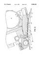
- FIG. 1 is a section through a metering head incorporating the present invention.
- FIG. 2 is a view similar to FIG. 1 showing flow patterns within the head.
- FIG. 3 is a plot of wet film weight leaving the coating applicator versus tube loading pressures (metering nip pressures) at different coating solids content.
- the coater head generally indicated at 10 applies coating to a application roll 12 having a surface 14 onto which the coating is applied for delivery into a application nip (not shown) of a size press where it is applied to a substrate and to be coated in the conventional manner.
- the coater head 10 is provided at its outlet end with a metering device which in the illustrated invention is in the form of a metering rod 16 mounted on an arm 18 and biased toward the roll 12 via pneumatic tubes or the like 20 (in the illustrated arrangement, two such tubes have been shown). These tubes that are intended to receive air under pressure, i.e. provide pneumatic pressure on the arm 18 to force the metering rod 16 against the application roll 12 and form the metering nip 17.
- a flow path generally indicated at 22 includes an expansion or a homogenization chamber 24 at its inlet end and a metering chamber 26 adjacent to the metering rod 16 at its outlet end.
- a shear developing passage 28 forms the portion of the flow path 22 that connects the homogenization chamber 24 to the metering chamber 26.
- a mixing passage 30 formed adjacent to the surface 14 of the application roll 12 opens into the metering chamber 26 and is provided with a throttle 32 (restriction of the passage 30) adjacent to the opening of the passage 30 into the metering chamber 26.
- the prime purpose of the mixing passage 30 is to ensure better mixing of the coating fluid leaving the vortex in the mixing chamber 26 with the fresh coating fluid entering the system and to ensure there is no entrainment of air with the roll surfacel4.
- the shape of the mixing passage 30 gradually increases in width (spacing from the surface 14) in a direction upstream of the direction of movement of surface 14 as indicated by the arrow 34.
- the passage 30 is provided with a restriction as indicated at 36 adjacent to the free end of a sealing blade 38 which limits the rearward flow of coating fluid through the openings 40 in the doctor blade. This rearward flow must be maintained at least at a selected minimum to ensure there is no air entrainment into the mixing passage 30 with the recirculating flow as will be described in more detail below.
- the blade 38 is not essential to the invention and may be omitted with an appropriately designed mixing passage that prevent air entrainment into the metering chamber 26
- An inlet header 42 delivers coating liquid into the head 10 and directs the coating liquid from the header 42 into the chamber 24 via passage 44.
- the shear developing passage 28 is important to permit operation with relatively high solids content coating formulations (high viscosity coating formulations), thus, the length l measured from the inlet end 45 at the chamber 24 to the outlet end 48 emptying into the chamber 26 combined with the thickness t of the passage are designed in known manner to generate sufficient shear or resistance to flow of the coating formulation therethrough to significantly reduce its viscosity and thereby facilitate the application of low coat weights to the roll 12 as it leaves the metering nip 17 between the roll 12 and rod 16.
- the viscosity of a coating fluid having a solids content of at least about 58% required, a length 1 of at least 100 mm for a passage having a thickness t 3 mm to effectively reduce the viscosity by one order of magnitude for the specific formulation being used and this permitted reduction of the coat weight applied in the application nip (not shown) by about 25%.
- the length l may be shorter if the thickness or height t is also reduced, i.e. l may be changed depending on the dimension t in known manner to accommodate different viscosity and different desired changes in viscosity. It will be apparent that there are limits to the solids contents of the coatings that may effectively be treated to reduce their viscosity for better performance.
- the metering chamber 26 must also be properly sized to maintain a stable vortex or the coating application will not be uniform.
- the unobstructed space 47 defined on a pair of opposite sides by an expansion angle ot i.e. the angle ⁇ from the nip 17 between the surface 14 and the adjacent surface of the arm 18 must be at least 25°. It is also important that the length of the unobstructed space 47 in the metering chamber 26 as measured from the nip 17 to the portion of rear wall 46 of the chamber 26 within the angle ⁇ as indicated by the radius r be at least 40 mm and not greater than 60 mm.
- the vortex formed in the chamber 26 becomes too restricted and generates instabilities that affect the ability of the metering nip to uniformly meter the amount of coating applied and similarly if the length r is too long control of the vortex is lost and instabilities that affect the metering are generated.
- the space 48 above the vortex formed by the angle cc should not be excessive.
- outlet end of the passage at 28, i.e. the inlet into the chamber 26 extend through the rear wall 46 preferably into the space 48, i.e. on the side of the portion of the wall 46 within the angle a remote from the surface 14 although it may be directed into the chamber 26 at any point above the opening into the mixing passage 30.
- the opening as indicated at 50 from the chamber 26 to the mixing passage 30 is provided with a throttle 32 having a throttle gap or height indicated at T which will normally be 1 to 3 mm.
- gap T controls the flow between the mixing passage 30 and the metering chamber 26 as well as the pressure in the chamber 26 and thus must be appropriately set.
- the throttle 32 is spaced from the nip 17 by length along the surface 14 indicated by the dimension L,.
- This dimension L in effect defines the size of the chamber 26 in a manner similar to the dimension r.
- L better defines the length along the surface 14 immediately upstream of the nip where unstable vortexes may form. This length L should not exceed 65 mm.
- the length of the mixing passage 30 measured in the direction of the arrow 34 must be sufficient to prevent air entrainment with the return or recycled fluid 70 accompanying the surface 14 as it moves into and under the coater head 10.
- this mixing passage 30 will have a length of at least about 20 mm measured upstream from throttle 32.
- the width or thickness of the passage 30 measured perpendicular from the surface 14 must be set to prevent air entrainment (thus may differ if a blade 38 is used), and generally will be about 1 to 3 mm at the throttle 36 and will expand to about 6 mm at its upstream end (restriction 36 in the illustrated arrangement).
- the coating formulation passes from the header 42 passage 44 into the homogenizing chamber 24 and from that chamber into the passage 28 where shear is applied to reduce the viscosity of coating formulation as required.
- the coating fluid then enters the metering chamber 26 and is diverted to flow as indicated by the arrow 60 down along the rear face 46 of the chamber 26 and into the opening 50 between the mixing passage 30 and the metering chamber 26.
- This flow 60 is mixed to a limited degree and entrained with or entrains some of the flow from the stable vortex 62 to be described below as schematically represented by the arrow 64 to provide a combined flow 68 entering the opening 50.
- This combined flow 68 passes through the throttle 32, i.e. between the throttle point 32 and the surface 14 of the roll 12 into the mixing passage 30 where the combined flow 68 is entrained by the in-coming recirculating flow generally indicated at 70 that travels with the surface 14.
- This flow 70 entrains fresh coating from the combined coating flow 68 and reverses its direction of flow as indicated by the arrow 72 to induce flow of the layer 70 plus the entrained fresh coating through the throttle 32 and into the chamber 26 moving in the direction of the arrow 34, i.e.
- a stable vortex 62 is formed by the excess fluid delivered to the nip 17 and not forming part of the wet film 74.
- the length L is too long, unstable vortices will be developed at the interface of the stable vortex 62 and the surface of the material carried by the roll 12 or surface 14 and the mixing passage 30 to the nip 17 and these vortices will further disrupt the wet film 74 and in many cases may be detrimental to wet film uniformity.
- the length L must not be too long as it defines the time for generating eddies in the incoming coating flowing toward the nip 17.
- the passage 28 had a thickness t of 3 mm and a length l of 11 cm.
- the radius r was 4.5 cm and the length L 5.5 cm.
- the passage 30 rearward of the throttle 32 to the tip of the blade 38, i.e. notch 34 was 6 cm and the angle a was about 25°.
- the wet film weight in grams/m 2 of the surface area of the surface 14 was measured using different loading tube pressures in the tubes 20 and compared with a control. It can be seen from FIG. 3 that at high solids content of 59.3% (of the present invention) was able to be applied a significant lower film weight using the present invention than was obtainable by the control (the same device less the cross-hatched element indicated at 100 and 102 in FIG. 1). However, at low solids content, there appears to be minimal difference.
- the important feature intended to be obtained by the present invention is to permit the use of high solids content above 59% (lower solids content, for example, 58 or 57% significantly increase the cost of coating and generally do not develop the same coating appearance as the higher solids coating composition).
- a blade 38 at the outlet (upstream) end of the mixing passage 30 the blade need not be provided but in such a case, a second throttle or a weir is preferably provided to slightly narrow the passage between the surface 14 and the coater head.
Landscapes
- Coating Apparatus (AREA)
- Paper (AREA)
Abstract
Description
Claims (19)
Priority Applications (6)
| Application Number | Priority Date | Filing Date | Title |
|---|---|---|---|
| US08/890,409 US5902401A (en) | 1997-07-09 | 1997-07-09 | Coater head |
| CA002294065A CA2294065C (en) | 1997-07-09 | 1998-07-07 | Coater head |
| PCT/CA1998/000657 WO1999002776A1 (en) | 1997-07-09 | 1998-07-07 | Coater head |
| DE19882522T DE19882522T1 (en) | 1997-07-09 | 1998-07-07 | Coater head |
| SE9904743A SE514541C2 (en) | 1997-07-09 | 1999-12-23 | coater |
| FI20000031A FI119651B (en) | 1997-07-09 | 2000-01-07 | The coating station |
Applications Claiming Priority (1)
| Application Number | Priority Date | Filing Date | Title |
|---|---|---|---|
| US08/890,409 US5902401A (en) | 1997-07-09 | 1997-07-09 | Coater head |
Publications (1)
| Publication Number | Publication Date |
|---|---|
| US5902401A true US5902401A (en) | 1999-05-11 |
Family
ID=25396635
Family Applications (1)
| Application Number | Title | Priority Date | Filing Date |
|---|---|---|---|
| US08/890,409 Expired - Lifetime US5902401A (en) | 1997-07-09 | 1997-07-09 | Coater head |
Country Status (6)
| Country | Link |
|---|---|
| US (1) | US5902401A (en) |
| CA (1) | CA2294065C (en) |
| DE (1) | DE19882522T1 (en) |
| FI (1) | FI119651B (en) |
| SE (1) | SE514541C2 (en) |
| WO (1) | WO1999002776A1 (en) |
Cited By (6)
| Publication number | Priority date | Publication date | Assignee | Title |
|---|---|---|---|---|
| US6017419A (en) * | 1997-09-16 | 2000-01-25 | Voith Sulzer Paper Technology North America, Inc. | Method and assembly for storing, transporting and using a metering size press rod assembly in a paper-making machine |
| US6343501B1 (en) | 2000-03-08 | 2002-02-05 | Polyvalor S.E.C. | System and method for determining the process viscosity of a fluid in a film metering device |
| WO2005123269A1 (en) * | 2004-06-18 | 2005-12-29 | Voith Patent Gmbh | Doctor blade device |
| US20130153595A1 (en) * | 2011-12-14 | 2013-06-20 | Marchesini Group S.P.A. | Apparatus For Regulating Release Of Tablets Into Cells Of A Heat Formed Strip |
| EP3023163A1 (en) * | 2014-11-18 | 2016-05-25 | Valmet Technologies, Inc. | Sealing blade |
| US9925555B2 (en) | 2016-02-08 | 2018-03-27 | Valmet Technologies, Inc. | Folded sealing blade for a coating applicator |
Families Citing this family (1)
| Publication number | Priority date | Publication date | Assignee | Title |
|---|---|---|---|---|
| WO2020131311A1 (en) | 2018-12-18 | 2020-06-25 | Exxonmobil Research And Engineering Company | Modified asphalts and methods for producing the same |
Citations (9)
| Publication number | Priority date | Publication date | Assignee | Title |
|---|---|---|---|---|
| US4396684A (en) * | 1979-07-20 | 1983-08-02 | Mitsubishi Paper Mills, Ltd. | Heat-sensitive recording paper causing reduced thermal head abrasion |
| US4405661A (en) * | 1981-09-10 | 1983-09-20 | Beloit Corporation | Blade type fountain coater and method |
| US4688516A (en) * | 1984-01-07 | 1987-08-25 | Jagenberg Ag | Device for coating webs of material traveling over a backing roll to a controlled thickness |
| US4780336A (en) * | 1987-04-06 | 1988-10-25 | Consolidated Papers, Inc. | Doctor blade for paper coater |
| US4839201A (en) * | 1987-12-03 | 1989-06-13 | Valmet Paper Machinery Inc. | Method and apparatus for applying coating liquid to a moving base |
| US4945855A (en) * | 1984-05-11 | 1990-08-07 | Valmet Paper Machinery Inc. | Coater |
| US5078081A (en) * | 1989-06-22 | 1992-01-07 | J. M. Voith Gmbh | Device for coating a material web |
| US5192591A (en) * | 1991-11-14 | 1993-03-09 | Beloit Technologies, Inc. | Short dwell coater apparatus |
| US5397601A (en) * | 1992-01-30 | 1995-03-14 | Valmet Paper Machinery, Inc. | Size press having a detachable throttle |
Family Cites Families (2)
| Publication number | Priority date | Publication date | Assignee | Title |
|---|---|---|---|---|
| US4396648A (en) * | 1982-02-08 | 1983-08-02 | Consolidated Papers, Inc. | Paper coating apparatus and method |
| DE9417321U1 (en) * | 1994-10-28 | 1994-12-08 | Voith Sulzer Papiermaschinen GmbH, 89522 Heidenheim | Application unit for direct or indirect application of a liquid or pasty medium |
-
1997
- 1997-07-09 US US08/890,409 patent/US5902401A/en not_active Expired - Lifetime
-
1998
- 1998-07-07 WO PCT/CA1998/000657 patent/WO1999002776A1/en active Application Filing
- 1998-07-07 CA CA002294065A patent/CA2294065C/en not_active Expired - Fee Related
- 1998-07-07 DE DE19882522T patent/DE19882522T1/en not_active Ceased
-
1999
- 1999-12-23 SE SE9904743A patent/SE514541C2/en not_active IP Right Cessation
-
2000
- 2000-01-07 FI FI20000031A patent/FI119651B/en not_active IP Right Cessation
Patent Citations (9)
| Publication number | Priority date | Publication date | Assignee | Title |
|---|---|---|---|---|
| US4396684A (en) * | 1979-07-20 | 1983-08-02 | Mitsubishi Paper Mills, Ltd. | Heat-sensitive recording paper causing reduced thermal head abrasion |
| US4405661A (en) * | 1981-09-10 | 1983-09-20 | Beloit Corporation | Blade type fountain coater and method |
| US4688516A (en) * | 1984-01-07 | 1987-08-25 | Jagenberg Ag | Device for coating webs of material traveling over a backing roll to a controlled thickness |
| US4945855A (en) * | 1984-05-11 | 1990-08-07 | Valmet Paper Machinery Inc. | Coater |
| US4780336A (en) * | 1987-04-06 | 1988-10-25 | Consolidated Papers, Inc. | Doctor blade for paper coater |
| US4839201A (en) * | 1987-12-03 | 1989-06-13 | Valmet Paper Machinery Inc. | Method and apparatus for applying coating liquid to a moving base |
| US5078081A (en) * | 1989-06-22 | 1992-01-07 | J. M. Voith Gmbh | Device for coating a material web |
| US5192591A (en) * | 1991-11-14 | 1993-03-09 | Beloit Technologies, Inc. | Short dwell coater apparatus |
| US5397601A (en) * | 1992-01-30 | 1995-03-14 | Valmet Paper Machinery, Inc. | Size press having a detachable throttle |
Cited By (11)
| Publication number | Priority date | Publication date | Assignee | Title |
|---|---|---|---|---|
| US6017419A (en) * | 1997-09-16 | 2000-01-25 | Voith Sulzer Paper Technology North America, Inc. | Method and assembly for storing, transporting and using a metering size press rod assembly in a paper-making machine |
| US6343501B1 (en) | 2000-03-08 | 2002-02-05 | Polyvalor S.E.C. | System and method for determining the process viscosity of a fluid in a film metering device |
| WO2005123269A1 (en) * | 2004-06-18 | 2005-12-29 | Voith Patent Gmbh | Doctor blade device |
| US20070113780A1 (en) * | 2004-06-18 | 2007-05-24 | Christoph Henninger | Doctor device |
| US8418645B2 (en) | 2004-06-18 | 2013-04-16 | Voith Patent Gmbh | Doctor device |
| US20130153595A1 (en) * | 2011-12-14 | 2013-06-20 | Marchesini Group S.P.A. | Apparatus For Regulating Release Of Tablets Into Cells Of A Heat Formed Strip |
| US9135769B2 (en) * | 2011-12-14 | 2015-09-15 | Marchesini Group S.P.A. | Apparatus for regulating release of tablets into cells of a heat formed strip |
| EP3023163A1 (en) * | 2014-11-18 | 2016-05-25 | Valmet Technologies, Inc. | Sealing blade |
| CN105603822A (en) * | 2014-11-18 | 2016-05-25 | 维美德技术有限公司 | Sealing blade |
| CN105603822B (en) * | 2014-11-18 | 2018-04-10 | 维美德技术有限公司 | Seal blades |
| US9925555B2 (en) | 2016-02-08 | 2018-03-27 | Valmet Technologies, Inc. | Folded sealing blade for a coating applicator |
Also Published As
| Publication number | Publication date |
|---|---|
| CA2294065C (en) | 2006-06-06 |
| SE9904743D0 (en) | 1999-12-23 |
| FI119651B (en) | 2009-01-30 |
| CA2294065A1 (en) | 1999-01-21 |
| SE9904743L (en) | 2000-02-29 |
| DE19882522T1 (en) | 2000-05-31 |
| SE514541C2 (en) | 2001-03-12 |
| FI20000031A7 (en) | 2000-03-03 |
| WO1999002776A1 (en) | 1999-01-21 |
Similar Documents
| Publication | Publication Date | Title |
|---|---|---|
| US4945855A (en) | Coater | |
| US7338559B2 (en) | Apparatus for decreasing skip coating on a paper web | |
| EP0804292B1 (en) | Method and apparatus for coating substrates using an air knife | |
| US3916077A (en) | Web coating method | |
| US2252204A (en) | Method and apparatus for coating paper | |
| US5665163A (en) | Film applicator with entrained air removal and surface control | |
| JPH01194966A (en) | Method and apparatus for adapting and adding coating substance to moving substrate | |
| US5902401A (en) | Coater head | |
| US6001179A (en) | Coating medium applicator with guide surface | |
| EP0675984A1 (en) | Method of minimizing skip coating on a paper web | |
| CA2325909C (en) | Method and apparatus for the high speed application of coating to a traveling paper web | |
| US2865260A (en) | Flow control apparatus | |
| JPS5830365A (en) | Coating apparatus | |
| JPH09187724A (en) | Paper web coating method and apparatus | |
| US3799111A (en) | Web coating apparatus | |
| US5683510A (en) | Coater with air collector | |
| US4407224A (en) | Apparatus for high speed size application | |
| Triantafillopoulos et al. | Operational issues in high speed curtain coating of paper | |
| US5776252A (en) | Assembly for preventing striping in a short dwell time applicator | |
| JPH08507964A (en) | Short dwell coater device | |
| FI109043B (en) | Apparatus for applying a coating of coating material to a moving paper or cardboard web | |
| US20020172771A1 (en) | Short dwell time coater and method | |
| JPH0451905Y2 (en) | ||
| US5914155A (en) | Method and applicator for direct or indirect application of a liquid or pasty coating medium onto a traveling material web, notably of paper or cardboard | |
| CA2152619A1 (en) | Method of minimizing skip coating on a paper web |
Legal Events
| Date | Code | Title | Description |
|---|---|---|---|
| AS | Assignment |
Owner name: MACMILLAN BLOEDEL LIMITED, CANADA Free format text: ASSIGNMENT OF ASSIGNORS INTEREST;ASSIGNORS:ELVIDGE, DAVID RICHARD;SMITH, MALCOLM KENNETH;REGLAT, OLIVIER;AND OTHERS;REEL/FRAME:008687/0403;SIGNING DATES FROM 19970704 TO 19970707 |
|
| AS | Assignment |
Owner name: MB PAPER LIMITED, CANADA Free format text: ASSIGNMENT OF ASSIGNORS INTEREST;ASSIGNOR:MACMILLAN BLOEDEL LIMITED;REEL/FRAME:009279/0226 Effective date: 19980529 |
|
| STCF | Information on status: patent grant |
Free format text: PATENTED CASE |
|
| AS | Assignment |
Owner name: PACIFICA PAPERS INC., CANADA Free format text: MERGER;ASSIGNORS:PACIFICA PAPERS INC.;PACIFICA INDUSTRIES LTD.;REEL/FRAME:013663/0108 Effective date: 19990312 |
|
| FPAY | Fee payment |
Year of fee payment: 4 |
|
| AS | Assignment |
Owner name: PACIFICA PAPERS INC., CANADA Free format text: RELEASE OF SECURITY INTEREST;ASSIGNOR:CANADIAN IMPERIAL BANK OF COMMERCE;REEL/FRAME:013552/0473 Effective date: 20020628 |
|
| AS | Assignment |
Owner name: NORSKE SKOG CANADA LIMITED, CANADA Free format text: MERGER;ASSIGNORS:PACIFICA PAPERS INC.;NORSKE SKOG CANADA LIMITED;REEL/FRAME:013663/0105 Effective date: 20010901 Owner name: PACIFICA PAPERS INC., CANADA Free format text: CHANGE OF NAME;ASSIGNOR:MB PAPER LIMITED;REEL/FRAME:013663/0116 Effective date: 19980615 Owner name: PACIFICA PAPERS INC., CANADA Free format text: MERGER;ASSIGNORS:PACIFICA PAPERS INC.;PACIFICA PAPER ACQUISITION COMPANY LTD.;REEL/FRAME:013663/0100 Effective date: 19980630 |
|
| AS | Assignment |
Owner name: CATALYST PAPER CORPORATION, CANADA Free format text: CHANGE OF NAME;ASSIGNOR:NORSKE SKOG CANADA LIMITED;REEL/FRAME:017388/0813 Effective date: 20051003 |
|
| FPAY | Fee payment |
Year of fee payment: 8 |
|
| AS | Assignment |
Owner name: CIT BUSINESS CREDIT CANADA INC., AS COLLATERAL AGE Free format text: SECURITY AGREEMENT;ASSIGNOR:CATALYST PAPER CORPORATION;REEL/FRAME:024055/0391 Effective date: 20100310 Owner name: COMPUTERSHARE TRUST COMPANY OF CANADA, AS COLLATER Free format text: SECURITY AGREEMENT;ASSIGNOR:CATALYST PAPER CORPORATION;REEL/FRAME:024055/0600 Effective date: 20100310 |
|
| FPAY | Fee payment |
Year of fee payment: 12 |
|
| AS | Assignment |
Owner name: CANADIAN IMPERIAL BANK OF COMMERCE, AS AGENT, CANA Free format text: SECURITY AGREEMENT;ASSIGNOR:CATALYST PAPER CORPORATION;REEL/FRAME:029009/0818 Effective date: 20120913 |
|
| AS | Assignment |
Owner name: CATALYST PAPER CORPORATION, CANADA Free format text: RELEASE OF LIEN ON PATENTS;ASSIGNOR:COMPUTERSHARE TRUST COMPANY OF CANADA;REEL/FRAME:029058/0463 Effective date: 20120914 |
|
| AS | Assignment |
Owner name: CATALYST PAPER CORPORATION, CANADA Free format text: RELEASE OF LIEN ON PATENTS;ASSIGNOR:JPMORGAN CHASE BANK, N.A., TORONTO BRANCH;REEL/FRAME:029075/0101 Effective date: 20120914 |
|
| AS | Assignment |
Owner name: CATALYST PAPER CORPORATION, CANADA Free format text: RELEASE OF LIEN ON PATENTS;ASSIGNOR:JPMORGAN CHASE BANK, N.A., TORONTO BRANCH;REEL/FRAME:029095/0280 Effective date: 20120914 |
|
| AS | Assignment |
Owner name: COMPUTERSHARE TRUST COMPANY OF CANADA, CANADA Free format text: SECURITY AGREEMENT;ASSIGNOR:CATALYST PAPER CORPORATION;REEL/FRAME:029133/0326 Effective date: 20120913 |
|
| AS | Assignment |
Owner name: CATALYST PAPER CORPORATION, CANADA Free format text: RELEASE BY SECURED PARTY;ASSIGNOR:CANADIAN IMPERIAL BANK OF COMMERCE;REEL/FRAME:048824/0526 Effective date: 20190315 Owner name: CATALYST PAPER CORPORATION, CANADA Free format text: RELEASE BY SECURED PARTY;ASSIGNOR:COMPUTERSHARE TRUST COMPANY OF CANADA;REEL/FRAME:048824/0559 Effective date: 20190315 |