EP0406462B1 - Behandlungstisch, insbesondere für physikalische Therapie - Google Patents
Behandlungstisch, insbesondere für physikalische Therapie Download PDFInfo
- Publication number
- EP0406462B1 EP0406462B1 EP89112281A EP89112281A EP0406462B1 EP 0406462 B1 EP0406462 B1 EP 0406462B1 EP 89112281 A EP89112281 A EP 89112281A EP 89112281 A EP89112281 A EP 89112281A EP 0406462 B1 EP0406462 B1 EP 0406462B1
- Authority
- EP
- European Patent Office
- Prior art keywords
- pillar
- hinge
- support surface
- treatment table
- casing
- Prior art date
- Legal status (The legal status is an assumption and is not a legal conclusion. Google has not performed a legal analysis and makes no representation as to the accuracy of the status listed.)
- Expired - Lifetime
Links
- 238000000554 physical therapy Methods 0.000 title claims abstract 3
- 241000876833 Emberizinae Species 0.000 claims 3
- 238000002560 therapeutic procedure Methods 0.000 description 2
- 229910000831 Steel Inorganic materials 0.000 description 1
- 238000010276 construction Methods 0.000 description 1
- 230000001771 impaired effect Effects 0.000 description 1
- 239000010959 steel Substances 0.000 description 1
- 238000003466 welding Methods 0.000 description 1
Images
Classifications
-
- A—HUMAN NECESSITIES
- A61—MEDICAL OR VETERINARY SCIENCE; HYGIENE
- A61G—TRANSPORT, PERSONAL CONVEYANCES, OR ACCOMMODATION SPECIALLY ADAPTED FOR PATIENTS OR DISABLED PERSONS; OPERATING TABLES OR CHAIRS; CHAIRS FOR DENTISTRY; FUNERAL DEVICES
- A61G13/00—Operating tables; Auxiliary appliances therefor
- A61G13/009—Physiotherapeutic tables, beds or platforms; Chiropractic or osteopathic tables
-
- A—HUMAN NECESSITIES
- A61—MEDICAL OR VETERINARY SCIENCE; HYGIENE
- A61G—TRANSPORT, PERSONAL CONVEYANCES, OR ACCOMMODATION SPECIALLY ADAPTED FOR PATIENTS OR DISABLED PERSONS; OPERATING TABLES OR CHAIRS; CHAIRS FOR DENTISTRY; FUNERAL DEVICES
- A61G13/00—Operating tables; Auxiliary appliances therefor
- A61G13/02—Adjustable operating tables; Controls therefor
- A61G13/08—Adjustable operating tables; Controls therefor the table being divided into different adjustable sections
Definitions
- the invention relates to a treatment table according to the preamble of patent claim 1.
- the vertical support column also has a fixed column core and a column jacket which is axially movable and tapered upwards on this column.
- One of the joints with which the lying surface sections are articulated is mounted in the tip of the column casing.
- a working cylinder in particular a hydraulic cylinder, is provided in the column core, which acts on the column jacket.
- Other working cylinders, which are articulated on the one hand on the column jacket and on the other hand on the lying surface sections, are also provided for pivoting the lying surface sections against one another.
- the support surface can only be pivoted with respect to the vertical support column about the joint axis running transversely to the longitudinal direction of the support surface, the joint of which is mounted in the tip of the column jacket.
- An operating table is known from EP 0 139 118 B1, in which the support surface, which is also composed of bed surface sections, can be tilted both transversely to its longitudinal direction and parallel to its longitudinal direction.
- a first frame is provided which is connected to a column head and is pivotably mounted about an axis running transversely to the longitudinal direction of the support surface.
- a bearing sleeve is provided on the first frame, in which a second frame, which is pivotably mounted about an axis parallel to the longitudinal direction of the bearing surface.
- a central section ie a central section of the bed surface of the support surface, is rigidly connected to the second frame.
- the object of the invention is to provide a treatment table of the type mentioned, in which the pivotability of the support surface can also be achieved about the longitudinal axis and the axis extending transversely thereto with little design effort.
- the bearing point for the connecting element can be realized without considerable design effort in that the hinge pin of the connecting hinge is pivotally mounted on a bearing pin fastened in the tip of the column jacket, the axis of which runs parallel to the longitudinal axis of the bearing surface.
- a working cylinder which is preferably designed as a hydraulic cylinder, can be supported in an articulated manner on the outer lateral surface of the column jacket and can engage directly on the joint pin of the connecting joint at an articulation point.
- the additional working cylinders which are supported on the column casing and on the lying surface sections, can also perfectly carry out the pivoting about the longitudinal axis of the lying surface, the articulation points on the column casing and / or on the lying surface sections are designed as ball joints.
- the support surface can be divided in its longitudinal direction into four lying surface sections, which are connected to one another via three joints.
- the middle of the three joints is designed as the connecting joint.
- This is supported on the tapered column jacket by the bearing pin, the axis of which runs parallel to the longitudinal axis of the bearing surface.
- the treatment table can be used in many ways. It is not only suitable as a treatment table for massage purposes, but can also serve as a special table, operating table, therapy chair or therapy stool, as an extension bench, inclined plane or patient lifting platform and the like.
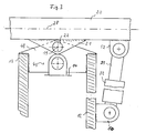
- a treatment table 1 shown in FIG. 1 as an exemplary embodiment of the invention has a support surface 2, which in the longitudinal direction consists of several lying surface sections 3, 4, 5, 6, d. H. in the embodiment of four lying surface sections, is composed.
- the four lying surface sections are connected to one another via three joints 7, 8, 9.
- the support surface 2 is mounted on a vertical telescopic support column 10 via the central joint 8, which is designed as a connecting joint.
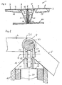
- the bearing point is explained in more detail with reference to Figures 2 and 3.
- Working cylinders 15, 16, 17, 18, which are preferably designed as hydraulic cylinders, are provided for adjusting the support surface or lying surface sections in different positions depending on the treatment.
- the vertical support column 10 has a column core 11 which is anchored in a base 27. On this fixed column core 11, a column jacket 12 is axially displaceably mounted, so that the support column 10 is telescopic is.
- the working cylinder 14 is supported on the base 27 or on a base piece of the column core 11 and engages on the column jacket 12 in the area of the column jacket tip 13.
- the mode of action of this support column is the same as that known from DE 30 16 387 C2.
- the working cylinders 16, 17 are supported in ball joints 24, 25 on the outer surface of the column casing 12 and engage the lying surface sections 4 and 5, which are connected to the connecting joint 8, in ball joints 23, 26.
- the working cylinders 15 and 18 are connected to the lying surface sections 3 and 4 or 5 and 6.
- the control of the working cylinders 15 to 18 takes place in a known manner, for example with the aid of a keyboard via control electronics, which actuates valves for the working medium of the working cylinders.
- the keyboard can be provided on the treatment table or can also be used for remote control of the working cylinders.
- the connecting joint 8 and thus the entire bearing surface 2 can be pivoted about a longitudinal axis 19.
- a hinge pin 20 is mounted on a bearing pin 22.
- the axis of the bearing pin 22 is parallel to the longitudinal direction of the bearing surface 2 and runs perpendicular to the hinge axis 28 of the connecting joint 8 and perpendicular to the column axis 30 of the vertical support column 10.
- the hinge pin 20, which extends over the entire width the support surface 2 extends, is provided with molded, for example welded on support jaws 21 and 31 which support the hinge pin 20 on the bearing pin 22.
- the lying surface sections 4 and 5 with hinges, of which a hinge 47 is shown, are pivotably mounted on the hinge pin 20.
- the bearing pin 22 is supported on the column jacket tip 13 on a support 48.
- the support 48 is connected to the column jacket tip 13, preferably by welding.
- the support jaws 21 and 31 and the support 48 can be made of flat steel, the support 48 protruding between the two support jaws 21 and 31 and the transverse bearing pin 23 connecting these elements to support the hinge pin 20 and thus the bearing surface 2.
- FIGS. 2 and 3 It can also be seen from FIGS. 2 and 3 that the working cylinder 14, which is guided in the column core 11, is connected to the support 48 via an articulation point 49.
- a further working cylinder 32 which is also preferably designed as a hydraulic cylinder, is supported in an articulation point 50 on the outside of the column jacket 12.
- the working cylinder 32 engages with its piston on the piston rod 51 at a hinge point 52 on the hinge pin 20 of the connecting joint 8.
- the working cylinder 32 can also be operated in a known manner by remote control or by keyboard and corresponding control electronics. Through the working cylinder 32, however, it is achieved that the hinge pin 20 and thus the articulated support surface 2 can additionally be pivoted about the longitudinal axis 19, which extends perpendicular to the hinge axis 28.
- the working cylinder 32 can pivot in a vertical plane, in which the joint axis 28 also lies, on the column jacket in the joint point 50.
Landscapes
- Health & Medical Sciences (AREA)
- Life Sciences & Earth Sciences (AREA)
- Public Health (AREA)
- Biomedical Technology (AREA)
- Animal Behavior & Ethology (AREA)
- General Health & Medical Sciences (AREA)
- Engineering & Computer Science (AREA)
- Veterinary Medicine (AREA)
- Biophysics (AREA)
- Orthopedic Medicine & Surgery (AREA)
- Physical Education & Sports Medicine (AREA)
- Rehabilitation Therapy (AREA)
- Accommodation For Nursing Or Treatment Tables (AREA)
- Pharmaceuticals Containing Other Organic And Inorganic Compounds (AREA)
Description
- Die Erfindung betrifft einen Behandlungstisch nach dem Oberbegriff des Patentanspruchs 1.
- Bei einem derartigen aus der US-A 25,20,455 bekannten Behandlungstisch wird die quer zur Längsrichtung der Auflagefläche sich erstreckende Achse über einen quer verlaufenden Rahmen und an geformte Lagerschenkel an der in Längsrichtung verlaufenden Achse abgestützt.
- Bei einem weiteren aus der DE 3016 387 C2 bekannten Behandlungstisch weist die vertikale Tragsäule ebenfalls einen feststehenden Säulenkern und einen auf diesem axial beweglichen, nach oben zugespitzten Säulenmantel auf. Eines der Gelenke, mit denen die Liegeflächenteilstücke aneinandergelenkt sind, ist in der Spitze des Säulenmantels gelagert. Zur Höhenverstellung ist im Säulenkern ein Arbeitszylinder, insbesondere Hydraulikzylinder, vorgesehen, der am Säulenmantel angreift. Weitere Arbeitszylinder, die einerseits am Säulenmantel und andererseits an den Liegeflächenteilstücken angelenkt sind, sind zur Verschwenkung der Liegeflächenteilstücke gegeneinander ebenfalls vorhanden. Bei diesem bekannten Behandlungstisch ist die Auflagefläche bezüglich der vertikalen Tragsäule allerdings nur um die quer zur Längsrichtung der Auflagefläche verlaufende Gelenkachse, deren Gelenk in der Säulenmantelspitze gelagert ist, verschwenkbar.
- Aus dar EP O 139 118 B1 ist ein Operationstisch bekannt, bei dem die ebenfalls aus Liegenflächenteilstücken zusammengesetzte Auflagefläche sowohl quer zu ihrer Längsrichtung als auch parallel zu ihrer Längsrichtung verkantet werden kann. Hierzu ist ein mit einem Säulenkopf verbundener erster Rahmen vorgesehen, der um eine quer zur Längsrichtung der Auflagefläche verlaufende Achse schwenkbar gelagert ist. Ferner ist am ersten Rahmen eine Lagerhülse vorgesehen, in welcher ein zweiter Rahmen, der um eine zur Längsrichtung der Auflagefläche parallele Achse schwenkbar gelagert ist. Mit dem zweiten Rahmen ist ein Mittelabschnitt, d. h. ein mittleres Liegeflächenteilstück der Auflagefläche, starr verbunden. Auf diese Weise erreicht man dann mit Hilfe der beiden auf den Säulenkopf aufgesetzten Rahmen, mit deren oberen zweiten, um die Längsachse verschwenkbaren Rahmen das Mittelstück der Auflagefläche starr verbunden ist, die Verschwenkbarkeit der Auflagefläche um eine Achse parallel zur Längsrichtung und quer zu dieser Achse.
- Aufgabe der Erfindung ist es, einen Behandlungstisch der eingangs genannten Art zu schaffen, bei welchem mit geringem konstruktiven Aufwand die Verschwenkbarkeit der Auflagefläche auch um die Längsachse und die quer dazu verlaufende Achse erreicht wird.
- Diese Aufgabe wird erfindungsgemäß durch die Merkmale des Patentanspruchs 1 gelöst.
- Die Lagerstelle für das Verbindungselement läßt sich ohne erheblichen konstruktiven Aufwand dadurch realisieren, daß der Gelenkbolzen des Verbindungsgelenks an einem in der Säulenmantelspitze befestigten Lagerbolzen, dessen Achse parallel zur Längsaches der Auflagefläche verläuft, schwenkbar gelagert ist.
- Um eine gesteuerte Verschwenkung um die Längsachse zu erreichen, kann ein Arbeitszylinder, welcher bevorzugt als Hydraulikzylinder ausgebildet ist, an der Außenmantelfläche des Säulenmantels gelenkig abgestützt sein und an einer Gelenkstelle direkt am Gelenkbolzen des Verbindungsgelenks angreifen.
- Damit die zusätzlichen Arbeitszylinder, welche am Säulenmantel und an den Liegeflächenteilstücken angestützt sind, ebenfalls einwandfrei die Verschwenkung um die Längsachse der Liegefläche mitvollführen können, sind die Anlenkstellen am Säulenmantel und/oder an den Liegeflächenteilstücken als Kugelgelenke ausgebildet.
- Bei dem Behandlungstisch kann die Auflagefläche in ihrer Längsrichtung in vier Liegeflächenteilstücke unterteilt sein, die über drei Gelenke miteinander verbunden sind. Das mittlere der drei Gelenke ist als das Verbindungsgelenk ausgebildet. Dieses ist über den Lagerbolzen, dessen Achse parallel zur Längsachse der Auflagefläche verläuft, am spitz zulaufenden Säulenmantel abgestützt. Dadurch wird die gewünschte zusätzliche Verschwenkbarkeit um die Längsachse der Auflagefläche mit äußerst einfachen konstruktiven Mitteln erreicht.
- Der Behandlungstisch kann vielseitig verwendet werden. Er eignet sich nicht nur als Behandlungstisch zu Massagezwecken, sondern kann auch als Spezialliege, Operationstisch, Therapiestuhl oder Therapiehocker, als Extensionsbank, Schiefe Ebene oder Patientenhebebühne und dgl. dienen.
- Es werden die gleichen Vorteile erreicht wie bei dem aus der DE 30 15 387 C2 bekannten Behandlungstisch, wobei trotz der zusätzlichen Verschwenkbarkeit um die Längsachse der Auflagefläche zusätzliche Unterbauten in Form von Standbeinen, Scherenunterbauten usw. fehlen, so daß wie bei der bekannten Behandlungsliege extreme Verstellungen der Liegeflächenteilstücke erreicht werden können, ohne daß die Verschwenkbarkeit um die Achse des Verbindungsgelenks beeinträchtigt ist. Außerdem wird durch die zusätzliche Verschwenkbarkeit die zur Verfügung stehende Hubstrecke nicht verringert.
- Anhand der beiliegenden Figuren wird an einem Ausführungsbeispiel die Erfindung noch näher erläutert. Es zeigt:
- Fig. 1
- eine Seitenansicht eines Behandlungstisches, der ein Ausführungsbeispiel der Erfindung ist;
- Fig. 2
- eine Detailansicht des in Fig. 1 gezeigten Behandlungstisches im Bereich der Lagerstelle der Auflagefläche an der vertikalen Tragsäule; und
- Fig. 3
- die in der Fig. 2 gezeigte Lagerstelle in senkrechter Blickrichtung dazu.
- Ein in der Fig. 1 als Ausführungsbeispiel der Erfindung dargestellter Behandlungstisch 1 besitzt eine Auflagefläche 2, welche in Längsrichtung aus mehreren Liegeflächenteilstücken 3, 4, 5, 6, d. h. beim Ausführungsbeispiel aus vier Liegeflächenteilstücken, zusammengesetzt ist. Die vier Liegenflächenteilstücke sind über drei Gelenke 7, 8, 9 miteinander verbunden. Die Auflagefläche 2 ist an einer vertikalen teleskopierbaren Tragsäule 10 über das mittlere Gelenk 8, welches als Verbindungsgelenk ausgebildet ist, gelagert. Die Lagerstelle wird im einzelnen noch anhand der Figuren 2 und 3 näher erläutert.
- Zur Verstellung der Auflagefläche bzw. Liegeflächenteilstücke in unterschiedliche, von der Behandlung abhängige Lagen sind Arbeitszylinder 15, 16, 17, 18 vorgesehen, welche bevorzugt als Hydraulikzylinder ausgebildet sind.
- Die vertikale Tragsäule 10 besitzt einen Säulenkern 11, der in einem Sockel 27 verankert ist. An diesem feststehenden Säulenkern 11 ist ein Säulenmantel 12 axial verschiebbar gelagert, so daß die Tragsäule 10 teleskopierbar ausgebildet ist. Zur Höhenverstellung des Säulenmantels 12 dient ein im Säulenkern 11 vorhandener Arbeitszylinder 14, der bevorzugt als Hydraulikzylinder ausgebildet ist. Der Arbeitszylinder 14 ist am Sockel 27 oder an einem Bodenstück des Säulenkerns 11 abgestützt und greift am Säulenmantel 12 im Bereich der Säulenmantelspitze 13 an. Die Wirkungsweise dieser Tragsäule ist die gleiche wie die in der DE 30 16 387 C2 bekannten Tragsäule.
- Die Arbeitszylinder 16, 17 sind in Kugelgelenken 24, 25 an der äußeren Fläche des Säulenmantels 12 abgestutzt und greifen an die Liegeflächenteilstücke 4 und 5, welche mit dem Verbindungsgelenk 8 verbunden sind, in Kugelgelenken 23, 26 an.
- Ferner sind die Arbeitszylinder 15 und 18 mit den Liegeflächenteilstücken 3 und 4 bzw. 5 und 6 verbunden. Die Steuerung der Arbeitszylinder 15 bis 18 erfolgt in bekannter Weise beispielsweise mit Hilfe einer Tastatur über eine Steuerelektronik, welche Ventile für das Arbeitsmedium der der Arbeitszylinder betätigt. Die Tastatur kann an dem Behandlungstisch vorgesehen sein oder auch zur Fernbedienung der Arbeitszylinder dienen.
- Wie die Fig. 1 ferner zeigt, ist das Verbindungsgelenk 8 und damit die gesamte Auflagefläche 2 um eine Längsachse 19 verschwenkbar. Hierzu ist ein Gelenkbolzen 20 an einem Lagerbolzen 22 gelagert. Die Achse des Lagerbolzens 22 ist parallel zur Längsrichtung der Auflagefläche 2 und verläuft senkrecht zur Gelenkachse 28 des Verbindunsgelenks 8 und senkrecht zur Säulenachse 30 der vertikalen Tragsäule 10. Der Gelenkbolzen 20, welcher sich über die gesamte Breite der Auflagefläche 2 erstreckt, ist mit angeformten, beispielsweise angeschweißten Abstützbacken 21 und 31 versehen, die den Gelenkbolzen 20 auf dem Lagerbolzen 22 abstützen.
- Wie beispielsweise die Fig. 2 zeigt, sind die Liegeflächenteilstücke 4 und 5 mit Scharnieren, von denen ein Scharnier 47 gezeigt ist, am Gelenkbolzen 20 schwenkbar gelagert.
- Der Lagerbolzen 22 ist an der Säulenmantelspitze 13 an einer Abstützung 48 gelagert. Die Abstützung 48 ist mit der Säulenmantelspitze 13 bevorzugt durch Schweißen verbunden. Die Abstützbacken 21 und 31 sowie die Abstützung 48 können aus Flachstahl hergestellt sein, wobei die Abstützung 48 zwischen die beiden Abstützbacken 21 und 31 ragt und der quer verlaufende Lagerbolzen 23 diese Elemente zur Abstützung des Gelenkbolzens 20 und damit der Auflagefläche 2 miteinander verbindet.
- Aus den Figuren 2 und 3 ist ferner zu entnehmen, daß der Arbeitszylinder 14, welcher im Säulenkern 11 geführt ist, über eine Anlenkstelle 49 mit der Abstützung 48 verbunden ist. An dieser Abstützung 48 ist auch die als Lagerbolzen 22 ausgebildete Lagerstelle des Verbindungsgelenks 8 bzw. des Gelenkbolzens 20 vorgesehen. Dies zeigt, daß mit Hilfe eines geringfügigen konstruktiven Aufwands, ohne Behinderung der extremen Verschwenkbarkeit der Liegeflächenteilstücke, eine zusätzliche Verschwenkung um die Längsachse 19 erreicht wird.
- Wie die Fig. 3 noch zeigt, ist an der Außenseite des Säulenmantels 12 ein weiterer Arbeitszylinder 32, der ebenfalls bevorzugt als Hydraulikzylinder ausgebildet ist, in einer Gelenkstelle 50 abgestützt. Der Arbeitszylinder 32 greift mit seinem Kolben über die Kolbenstange 51 an einer Gelenkstelle 52 am Gelenkbolzen 20 des Verbindungsgelenks 8 an. Auch der Arbeitszylinder 32 kann in bekannter Weise durch Fernbedienung oder durch Tastatur und eine entsprechende Steuerungselektronik betätigt werden. Durch den Arbeitszylinder 32 wird jedoch erreicht, daß der Gelenkbolzen 20 und damit die daran angelenkte Auflagefläche 2 um die Längsachse 19, welche senkrecht zur Gelenkachse 28 verläuft, zusätzlich verschwenkbar ist. Der Arbeitszylinder 32 kann in einer vertikalen Ebene, in welcher auch die Gelenkachse 28 liegt, sich am Säulenmantel in der Gelenkstelle 50 verschwenken.
Claims (6)
- Behandlungstisch, insbesondere für physikalische Therapie, mit- einer Auflagefläche (2) aus Liegeflächenteilstücken (3, 4, 5, 6), die an ihren jeweiligen benachbarten Kanten mittels Gelenken (7, 8, 9) miteinander verbunden sind;- einer vertikalen Tragsäule (10), die mit einem feststehenden Säulenkern (11) und einem auf diesem axial beweglichen, nach oben zugespitzten Säulenmantel (12) teleskopartig ausgebildet ist;- eine in der Säulenmantelspitze (13) vorgesehene Lagerung für ein Gelenk, mit welchem die Auflagefläche (2) um eine quer zur Längsrichtung der Auflagefläche liegende Gelenkachse (28) schwenkbar mit dem Säulenmantel (12) verbunden ist;- einem im Säulenkern (11) angeordneten Arbeitszylinder (14), der zur Höhenverstellung am Säulenmantel (12) angreift;- weiteren Arbeitszylindern (16, 17), die einerseits am Säulenmantel (12) und andererseits an den Liegeflächenteilstücken (4, 5) angelenkt sind, und Arbeitszylindern (15, 18), die an der Liegeflächenteilstücken (3, 4 und 5, 6) angelenkt sind ; und- einem Verbindungsgelenk (8), mit welchem die Auflagefläche (2) um die quer zur Längsrichtung der Auflagefläche verlaufende Gelenkachse (28) verschwenkbar mit dem Säulenmantel (12) verbunden ist und an einer in der Säulenspitze (13) befestigten Lagerstelle (22) um eine zur Säulenachse (30) und zur Gelenkachse (28) senkrechte Längsachse (19) verschwenkbar gelagert ist,dadurch gekennzeichnet, daß- das Verbindungsgelenk (8) einen Gelenkbolzen (20) aufweist, dessen Länge der Breite der Auflagefläche (2) entspricht; und- an den Gelenkbolzen (20) zwei Abstützbacken (21, 31) angeformt sind, über welche der Gelenkbolzen (20) schwenkbar an der in der Säulenspitze (13) befestigten Lagerstelle (22) abgestützt ist.
- Behandlungstisch nach Anspruch 1 oder 2, dadurch gekennzeichnet, daß die Lagerstelle (22) für das Verbindungsgelenk als Lagerbolzen ausgebildet ist.
- Behandlungstisch nach Anspruch 1 oder 2, dadurch gekennzeichnet, daß am Verbindungsgelenk (8) ein Arbeitszylinder (32) angreift, der am höhenverstellbaren Säulenmantel (12) in einer zur Längsachse (19) senkrechten Ebene schwenkbar abgestützt ist.
- Behandlungstisch nach Anspruch 3, dadurch gekennzeichnet, daß der Arbeitszylinder (32) am Gelenkbolzen (20) angreift.
- Behandlungstisch nach einem der Ansprüche 1 bis 4, dadurch gekennzeichnet, daß die am Säulenmantel (12) und den Liegenflächenteilstücken (4, 5) abgestützten Arbeitszylinder (16, 17) in Kugelgelenken (23, 24, 25, 26) am Säulenmantel (12) und/oder den Liegenflächenteilstücken (4, 5) angelenkt sind.
- Behandlungstisch nach einem der Ansprüche 1 bis 5, dadurch gekennzeichnet, daß die Auflagefläche (2) in ihrer Längsrichtung aus vier Liegeflächenteilstücken (3, 4, 5, 6) besteht, die durch drei Gelenke (7, 8, 9) miteinander verbunden sind, wobei die Auflagefläche (2) über das mittlere, als Verbindungsgelenk (8) ausgebildete Gelenk mit dem Säulenmantel (12) verbunden ist, und dieses mittlere, als Verbindungsgelenk (8) ausgebildete Gelenk an der Lagerstelle um die Längsachse (19) verschwenkbar gelagert ist.
Priority Applications (3)
| Application Number | Priority Date | Filing Date | Title |
|---|---|---|---|
| EP89112281A EP0406462B1 (de) | 1989-07-05 | 1989-07-05 | Behandlungstisch, insbesondere für physikalische Therapie |
| DE89112281T DE58905851D1 (de) | 1989-07-05 | 1989-07-05 | Behandlungstisch, insbesondere für physikalische Therapie. |
| AT89112281T ATE95413T1 (de) | 1989-07-05 | 1989-07-05 | Behandlungstisch, insbesondere fuer physikalische therapie. |
Applications Claiming Priority (1)
| Application Number | Priority Date | Filing Date | Title |
|---|---|---|---|
| EP89112281A EP0406462B1 (de) | 1989-07-05 | 1989-07-05 | Behandlungstisch, insbesondere für physikalische Therapie |
Publications (2)
| Publication Number | Publication Date |
|---|---|
| EP0406462A1 EP0406462A1 (de) | 1991-01-09 |
| EP0406462B1 true EP0406462B1 (de) | 1993-10-06 |
Family
ID=8201588
Family Applications (1)
| Application Number | Title | Priority Date | Filing Date |
|---|---|---|---|
| EP89112281A Expired - Lifetime EP0406462B1 (de) | 1989-07-05 | 1989-07-05 | Behandlungstisch, insbesondere für physikalische Therapie |
Country Status (3)
| Country | Link |
|---|---|
| EP (1) | EP0406462B1 (de) |
| AT (1) | ATE95413T1 (de) |
| DE (1) | DE58905851D1 (de) |
Cited By (1)
| Publication number | Priority date | Publication date | Assignee | Title |
|---|---|---|---|---|
| EP0873740A2 (de) | 1997-04-21 | 1998-10-28 | Herbert Brustmann | Behandlungstisch |
Families Citing this family (3)
| Publication number | Priority date | Publication date | Assignee | Title |
|---|---|---|---|---|
| DE19607968A1 (de) * | 1996-03-01 | 1997-09-04 | Herbert Brustmann | Behandlungsliege |
| DE10113807C1 (de) | 2001-03-21 | 2002-08-14 | Herbert Brustmann | Höhenverstellbare Tragsäule eines Behandlungstisches, insbesondere für chirurgische Eingriffe |
| IT1400316B1 (it) * | 2010-03-25 | 2013-05-24 | Cipolla | Poltrona reclinabile per uso sportivo. |
Family Cites Families (6)
| Publication number | Priority date | Publication date | Assignee | Title |
|---|---|---|---|---|
| US2520455A (en) * | 1945-06-20 | 1950-08-29 | Ritter Co Inc | Surgical table with hydraulic adjusting system |
| GB910029A (en) * | 1960-05-06 | 1962-11-07 | Central Design Office Of The M | Universal operating table with automatic control |
| US3373454A (en) * | 1967-02-08 | 1968-03-19 | David T. Curtis | Device for moving injured persons |
| FR2192460A5 (de) * | 1972-07-10 | 1974-02-08 | Mathieu Pierre T Cie | |
| DE3016387C2 (de) * | 1980-04-29 | 1984-04-19 | Herbert 8190 Wolfratshausen Brustmann | Behandlungsliege |
| DE3328908A1 (de) | 1983-08-10 | 1985-02-28 | Stierlen-Maquet Ag, 7550 Rastatt | Operationstisch |
-
1989
- 1989-07-05 DE DE89112281T patent/DE58905851D1/de not_active Expired - Fee Related
- 1989-07-05 EP EP89112281A patent/EP0406462B1/de not_active Expired - Lifetime
- 1989-07-05 AT AT89112281T patent/ATE95413T1/de not_active IP Right Cessation
Cited By (1)
| Publication number | Priority date | Publication date | Assignee | Title |
|---|---|---|---|---|
| EP0873740A2 (de) | 1997-04-21 | 1998-10-28 | Herbert Brustmann | Behandlungstisch |
Also Published As
| Publication number | Publication date |
|---|---|
| EP0406462A1 (de) | 1991-01-09 |
| ATE95413T1 (de) | 1993-10-15 |
| DE58905851D1 (de) | 1993-11-11 |
Similar Documents
| Publication | Publication Date | Title |
|---|---|---|
| EP0724540B1 (de) | Scherenhubtisch | |
| DE2251808C3 (de) | Zahnärztlicher Patientenstuhl mit Parallelogrammtragarm | |
| EP1732840A1 (de) | Hebevorrichtung | |
| EP0016390B1 (de) | Schreitwerk | |
| EP0100490B1 (de) | Hubvorrichtung für insbesondere einen zahnärztlichen Patientenstuhl | |
| DE60022252T2 (de) | Massagevorrichtung zum Einbau in der Rückenlehne eines Sessels, versehen mit Massagedruckregulierung | |
| EP0406462B1 (de) | Behandlungstisch, insbesondere für physikalische Therapie | |
| EP0356761A1 (de) | Scherenhubvorrichtung, insbesondere für eine Arbeitsbühne | |
| DE3437092A1 (de) | Montagevorrichtung fuer fenster, tueren und dergleichen | |
| DE19604074B4 (de) | Hubvorrichtung für Pflegebetten | |
| DE8717735U1 (de) | Aufweitwerkzeug für Enden von dünnwandigen Blechrohren | |
| DE2727655C3 (de) | Fahrbare Grubenausbaueinheit | |
| EP2086489B1 (de) | Zahnärztlicher behandlungsstuhl | |
| EP1175881B1 (de) | Vorrichtung zur Führung eines Kopfteils am Ende eines Auflagetisches zur Patientenbehandlung | |
| EP1243239B1 (de) | Höhenverstellbare Tragsäule eines Behandlungstisches, insbesondere für chirurgische Eingriffe | |
| DE2227406A1 (de) | Fahrbare drehleiter | |
| DE2918646A1 (de) | Hubpodium bzw. - podest | |
| DE3153007C2 (de) | ||
| EP1447071A1 (de) | Therapie- und/oder Trainingsgerät | |
| DE2938330A1 (de) | Hoehenverstellvorrichtung fuer ein zahnaerztliches geraet | |
| DE19803130A1 (de) | Verfahren zur Bewegung einer Person sowie Vorrichtung für die Ausführung eines solchen Verfahrens | |
| EP0873740A2 (de) | Behandlungstisch | |
| EP0800810B1 (de) | Therapieliege | |
| DE3424070A1 (de) | Vorrichtung zur nach- bzw. fertigbearbeitung von bohrungen | |
| CH421381A (de) | Spitalbett |
Legal Events
| Date | Code | Title | Description |
|---|---|---|---|
| PUAI | Public reference made under article 153(3) epc to a published international application that has entered the european phase |
Free format text: ORIGINAL CODE: 0009012 |
|
| AK | Designated contracting states |
Kind code of ref document: A1 Designated state(s): AT BE CH DE FR GB IT LI NL SE |
|
| 17P | Request for examination filed |
Effective date: 19910220 |
|
| 17Q | First examination report despatched |
Effective date: 19920817 |
|
| GRAA | (expected) grant |
Free format text: ORIGINAL CODE: 0009210 |
|
| AK | Designated contracting states |
Kind code of ref document: B1 Designated state(s): AT BE CH DE FR GB IT LI NL SE |
|
| REF | Corresponds to: |
Ref document number: 95413 Country of ref document: AT Date of ref document: 19931015 Kind code of ref document: T |
|
| RIN1 | Information on inventor provided before grant (corrected) |
Inventor name: BRUSTMANN, HERBERT |
|
| ET | Fr: translation filed | ||
| REF | Corresponds to: |
Ref document number: 58905851 Country of ref document: DE Date of ref document: 19931111 |
|
| ITF | It: translation for a ep patent filed | ||
| GBT | Gb: translation of ep patent filed (gb section 77(6)(a)/1977) |
Effective date: 19931208 |
|
| PLBE | No opposition filed within time limit |
Free format text: ORIGINAL CODE: 0009261 |
|
| STAA | Information on the status of an ep patent application or granted ep patent |
Free format text: STATUS: NO OPPOSITION FILED WITHIN TIME LIMIT |
|
| 26N | No opposition filed | ||
| EAL | Se: european patent in force in sweden |
Ref document number: 89112281.4 |
|
| REG | Reference to a national code |
Ref country code: GB Ref legal event code: IF02 |
|
| PGFP | Annual fee paid to national office [announced via postgrant information from national office to epo] |
Ref country code: NL Payment date: 20050718 Year of fee payment: 17 |
|
| PGFP | Annual fee paid to national office [announced via postgrant information from national office to epo] |
Ref country code: CH Payment date: 20050722 Year of fee payment: 17 Ref country code: SE Payment date: 20050722 Year of fee payment: 17 |
|
| PGFP | Annual fee paid to national office [announced via postgrant information from national office to epo] |
Ref country code: BE Payment date: 20050725 Year of fee payment: 17 |
|
| PGFP | Annual fee paid to national office [announced via postgrant information from national office to epo] |
Ref country code: AT Payment date: 20050726 Year of fee payment: 17 Ref country code: GB Payment date: 20050726 Year of fee payment: 17 |
|
| PG25 | Lapsed in a contracting state [announced via postgrant information from national office to epo] |
Ref country code: GB Free format text: LAPSE BECAUSE OF NON-PAYMENT OF DUE FEES Effective date: 20060705 Ref country code: AT Free format text: LAPSE BECAUSE OF NON-PAYMENT OF DUE FEES Effective date: 20060705 |
|
| PG25 | Lapsed in a contracting state [announced via postgrant information from national office to epo] |
Ref country code: SE Free format text: LAPSE BECAUSE OF NON-PAYMENT OF DUE FEES Effective date: 20060706 |
|
| PGFP | Annual fee paid to national office [announced via postgrant information from national office to epo] |
Ref country code: FR Payment date: 20060719 Year of fee payment: 18 |
|
| PG25 | Lapsed in a contracting state [announced via postgrant information from national office to epo] |
Ref country code: LI Free format text: LAPSE BECAUSE OF NON-PAYMENT OF DUE FEES Effective date: 20060731 Ref country code: BE Free format text: LAPSE BECAUSE OF NON-PAYMENT OF DUE FEES Effective date: 20060731 Ref country code: CH Free format text: LAPSE BECAUSE OF NON-PAYMENT OF DUE FEES Effective date: 20060731 |
|
| PGFP | Annual fee paid to national office [announced via postgrant information from national office to epo] |
Ref country code: IT Payment date: 20060731 Year of fee payment: 18 |
|
| PG25 | Lapsed in a contracting state [announced via postgrant information from national office to epo] |
Ref country code: NL Free format text: LAPSE BECAUSE OF NON-PAYMENT OF DUE FEES Effective date: 20070201 |
|
| REG | Reference to a national code |
Ref country code: CH Ref legal event code: PL |
|
| EUG | Se: european patent has lapsed | ||
| GBPC | Gb: european patent ceased through non-payment of renewal fee |
Effective date: 20060705 |
|
| NLV4 | Nl: lapsed or anulled due to non-payment of the annual fee |
Effective date: 20070201 |
|
| PGFP | Annual fee paid to national office [announced via postgrant information from national office to epo] |
Ref country code: DE Payment date: 20070727 Year of fee payment: 19 |
|
| BERE | Be: lapsed |
Owner name: BRUMABA U. *BRUSTMANN Effective date: 20060731 |
|
| REG | Reference to a national code |
Ref country code: FR Ref legal event code: ST Effective date: 20080331 |
|
| PG25 | Lapsed in a contracting state [announced via postgrant information from national office to epo] |
Ref country code: FR Free format text: LAPSE BECAUSE OF NON-PAYMENT OF DUE FEES Effective date: 20070731 |
|
| PG25 | Lapsed in a contracting state [announced via postgrant information from national office to epo] |
Ref country code: DE Free format text: LAPSE BECAUSE OF NON-PAYMENT OF DUE FEES Effective date: 20090203 |
|
| PG25 | Lapsed in a contracting state [announced via postgrant information from national office to epo] |
Ref country code: IT Free format text: LAPSE BECAUSE OF NON-PAYMENT OF DUE FEES Effective date: 20070705 |