EP0405394A2 - Equipement d'abonné pour transmettre des données temporairement mémorisées à un récepteur d'appel radio muni d'un dispositif de sortie acoustique et/ou optique - Google Patents
Equipement d'abonné pour transmettre des données temporairement mémorisées à un récepteur d'appel radio muni d'un dispositif de sortie acoustique et/ou optique Download PDFInfo
- Publication number
- EP0405394A2 EP0405394A2 EP90112030A EP90112030A EP0405394A2 EP 0405394 A2 EP0405394 A2 EP 0405394A2 EP 90112030 A EP90112030 A EP 90112030A EP 90112030 A EP90112030 A EP 90112030A EP 0405394 A2 EP0405394 A2 EP 0405394A2
- Authority
- EP
- European Patent Office
- Prior art keywords
- subscriber
- subscriber device
- paging
- microprocessor
- call
- Prior art date
- Legal status (The legal status is an assumption and is not a legal conclusion. Google has not performed a legal analysis and makes no representation as to the accuracy of the status listed.)
- Granted
Links
Images

Classifications
-
- H—ELECTRICITY
- H04—ELECTRIC COMMUNICATION TECHNIQUE
- H04W—WIRELESS COMMUNICATION NETWORKS
- H04W88/00—Devices specially adapted for wireless communication networks, e.g. terminals, base stations or access point devices
- H04W88/18—Service support devices; Network management devices
- H04W88/185—Selective call encoders for paging networks, e.g. paging centre devices
-
- H—ELECTRICITY
- H04—ELECTRIC COMMUNICATION TECHNIQUE
- H04M—TELEPHONIC COMMUNICATION
- H04M1/00—Substation equipment, e.g. for use by subscribers
- H04M1/64—Automatic arrangements for answering calls; Automatic arrangements for recording messages for absent subscribers; Arrangements for recording conversations
- H04M1/65—Recording arrangements for recording a message from the calling party
- H04M1/658—Means for redirecting recorded messages to other extensions or equipment
Definitions
- the invention relates to a subscriber device according to the preamble of patent claim 1.
- the automatic dialer With the answering machine the message of the caller is recorded, then the automatic dialer is activated and the owner of the answering machine is automatically called via the European paging service or via the telecommunications network. For this purpose, the automatic dialer initiates a connection based on one or more previously stored phone numbers and when the called subscriber reports, the subscriber is asked (announcement text) to bring the answering machine owner to the phone.
- the message from the caller recorded by the answering machine can then be queried remotely by the owner of the answering machine via the telecommunications network using the code transmitter carried along. The call charges are not borne by the called party, but by the owner of the answering machine.
- the pager can be reached via a maximum of four numbers.
- code signals are formed which are fed to the VHF transmitters connected to the paging center for call transmission.
- the transmitted code signals are received and decoded by the pager. If the code set in the decoder matches the code received, an acoustic and an optical signal are resolved. The meaning of the code signals must be agreed between the pager and the calling party.
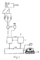
- a paging service referred to as a city call and shown in FIG. 1 is known, in which brief information is shown as digits or texts on the display D of the paging receiver FRE. These messages can be entered via the telephone set, telex, teletex or Btx terminals.
- City calls can transmit information in three call classes: Tone-only for tone pagers FRE, which can receive four agreed signals in accordance with the European paging service; Numeric for FRE numeric pagers to receive up to fifteen digits or special characters and Alphanumeric for FRE alphanumeric pagers to receive text (strings of digits and letters) up to eighty characters.
- City-Ruf is broadcast in regional zones (so-called call zones), with the coverage area covering approximately the entire catchment area of a large city.
- the paging network consists of the paging centers FVSt, the paging concentrators FK, the transmitters S and the paging receivers FRE.
- the paging exchange FVSt manages the subscriber data and controls the transmitters S via which a call is to be broadcast. Access from the public telecommunications networks to the paging network is possible with the same access code and depends only on the call class and the respective input device for the city call information.
- the end devices installed at the subscriber for the various postal services serve as input devices. For a numerical and text input from a simple telephone connection, special additional devices, for example, acoustically connectable DTMF transmitters, are required, since the FREF numeric paging receiver Require multi-frequency dialing (DTMF). If alphanumeric information is to be entered from a personal computer or home computer, it must be connected to an acoustic coupler or modem.
- DTMF FREF numeric paging receiver Require multi-frequency dialing
- a paging radio system for nationwide call networks in which not only voice announcements but also 10-digit numbers can be transmitted.
- a so-called adaptation transmission is provided in the paging center, which stores the dialing information of up to eighteen digits of the calling subscriber and also enables the calling subscriber to communicate with the call processor.
- a coupling of the adaptation transmission to a voice bus is provided for a time-limited voice message to the pager, a speech path being switched through from the caller's microphone to the pager's loudspeaker for a short time.
- Firefighters - calls can also be triggered by contacts.
- Answering machine and / or radio paging receiver can improve the accessibility of a called but absent subscriber. Due to the conception of the answering machine and the paging services, a fast message transmission is possible in the Subscriber device, especially answering machine, cached messages not possible.
- the invention is based on the object of designing a subscriber device in such a way that rapid transmission of temporarily stored messages to a radio paging receiver with an optical and / or acoustic output device is made possible.
- the subscriber device has the advantage that the calling subscriber can leave numeric, alphanumeric and spoken messages which are temporarily stored in the buffer of the subscriber device and are automatically transmitted to a pager with an optical and / or acoustic output device after the connection has been triggered. Another advantage is that the calling subscriber can transmit a message to a pager even if he does not know the paging subscriber number. If the subscriber device is designed in the form of an answering machine with message recording, it is not necessary for the calling subscriber with a view to a rapid transmission of his Message to reach the owner of the answering machine who is on the move via the paging service. Since the calling subscriber can leave his message, there are no two-way charges that are otherwise required, but the second call charge is borne by the owner of the answering machine.
- the new additional function of the subscriber device eliminates the need to call the owner of the answering machine while on the move. For the owner of the answering machine, the otherwise necessary call fee for the remote-controlled query of a message recorded by the answering machine of the caller is thus eliminated.
- the temporarily stored brief information can be shown as numbers or texts on the display of the pager.
- the radio call receiver also has an acoustic output device, voice announcements can also be transmitted in addition to this display of brief information on the display. Since modern answering machines are usually DTMF-capable and have facilities for forwarding calls via the European paging service, only the additional buffer is required as additional equipment.
- the embodiment of the subscriber device according to claim 2 has the advantage that modern comfort telephones with a DTMF-capable keyboard can be used to enter the message to be transmitted to the pager.
- the embodiment of the subscriber device according to claim 3 has the advantage that no additional device for entering the characters, i.e. Numbers or letters, is required.
- a paging arrangement is known from DE-OS 35 19 972, in which an arrangement for speech recognition is arranged in the paging center.
- This arrangement for speech recognition which is arranged centrally in the paging, performs a signal conversion of the numerical information spoken by the telephone subscriber into signals suitable for transmission via the paging transmitter.
- the acoustic control makes it possible for the calling subscriber to ensure that, for example, the correct telephone subscriber number for the pager is transmitted. If the subscriber device is voice-controlled and contains these devices for digital speech processing, the additional equipment expenditure to be provided for this is very low.
- the embodiment of the subscriber device according to claim 7 enables both remote monitoring of the subscriber device itself and remote monitoring of devices connected to the subscriber device.
- the radio paging receiver also has an acoustic output device
- acoustic room monitoring can also be carried out to supplement the function of alarm systems.
- Fig. 1 shows the structure of the City-Ruf paging service in the Federal Republic.
- the city call can also be used by the participants across borders, for example the paging service Alphapage in France, Teledrine in Italy and Europage in Great Britain. To do this, the City Ruf subscriber must log into an international European call zone. Due to the signal conversion in the subscriber device TE according to the invention, it is not necessary for the calling subscriber to enter his message using a special input device for paging information.
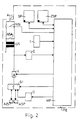
- the subscriber device TE shown in FIG. 2 is connected to the telecommunications network via the main connecting line AL.
- a microprocessor MP is arranged in the subscriber device TE and is connected to a number switch pulse contact NSI, an NSA contact NSA and a changeover switch S1. With the number switch pulse contact NSI pulse series are generated, the NSA contact is used to switch off the speech circuit during the dialing and with the switch S1 there is a switch to different message sources.
- the microprocessor MP is connected to a memory SP with dialing information (eg telephone numbers).
- the microprocessor MP takes over the function of an automatic dialing device and can also carry out a switching function.
- the microprocessor MP controls the exchange of switching information between the subscriber device TE and the control devices of the switching centers VSt or FVSt of the telecommunications network.
- the dialing information is generated in the subscriber device TE either with the number switch pulse contact NSI or with a generator G operating according to the multi-frequency code selection method.
- the subscriber device TE can, however, be used in all communication networks for switched connections, for example the answering machine can also be an integral part of a cordless telephone set, as is known from the magazine "JEI, June 89, p. 98 ff".
- a call signal arrives via the main connection line AL in the subscriber device TE, this is recognized by a call receiving circuit and a control signal for the microprocessor MP is triggered, which connects the call to the subscriber manufactures.
- the announcement text contained in the announcement memory ASP is read out and transmitted to the calling subscriber via the main connection line AL.
- the calling subscriber can either leave a spoken message, which is temporarily stored in the AZS recording memory for remote inquiry, or he gives with a telephone set that can generate signals using the multi-frequency code dialing method or with an acoustically coupled input device (code transmitter for generating DTMF characters) numeric messages for the radio paging receiver FRE.
- This numerical message can be, for example, the subscriber's telephone number.
- the digits are buffered in the buffer ZSP and the calling subscriber receives the final announcement.
- the microprocessor MP initiates a connection setup to the radio paging receiver FRE using the dialing information stored in the memory SP.
- the information in the buffer ZSP ie the sequence of digits in the case described, is read out and displayed on the optical output device D of the radio paging receiver FRE.
- the microprocessor MP reads out, for example when an alarm contact is actuated, the correspondingly entered message contained in the intermediate memory ZSP for transmission to the radio paging receiver FRE.
- the subscriber device TE contains a hybrid circuit GS with a transformer, but also electronic hybrid circuits with automatic line impedance adjustment and / or a line length-dependent gain control can also be used. Furthermore, a switchable amplifier V is connected to the microprocessor Mp, which ensures good voice quality, for example, during each phase of the message transmission. Furthermore, a receiver E for signals according to the DTMF method (double-tone multi-frequency method) is arranged in the subscriber device TE and is connected to the microprocessor MP. Modern answering machines generally contain the receiver E and the generator G. The receiver E is used to decode the code words required for remote access. With the generator G, the dial signals are generated. In the subscriber device TE according to the invention, the receiver E and the Generator G in addition to the signal conversion during the intermediate storage and transmission of the messages.
- DTMF method double-tone multi-frequency method
- the embodiment shown in FIG. 2 relates to the transmission of messages in the form of digits.
- a corresponding signal conversion is required in the subscriber device TE, with either telex, teletex or Btx terminals having to be installed as an input device for the calling subscriber, or a computer with an acoustic coupler or modem is.
- the speech signals supplied via the main connection line AL are fed to a speech analyzer SA in the subscriber device TE.
- a device SU for signal conversion of the recognized, spoken character is connected to the speech analyzer SA and the intermediate memory ZSP.
- the voice input can be carried out not only by the calling subscriber, but also by the owner of the subscriber device TE via a microphone M provided for telephony.
- a speech synthesis device SY is arranged in the subscriber device TE.
- the speech synthesis device SY is connected to the speech analyzer SA.
- a hearing device LA provided for telephony can be connected to the speech synthesis device SY as the speech output device LA.
Applications Claiming Priority (2)
| Application Number | Priority Date | Filing Date | Title |
|---|---|---|---|
| DE3920982A DE3920982A1 (de) | 1989-06-27 | 1989-06-27 | Teilnehmereinrichtung zur uebermittlung zwischengespeicherter nachrichten zu einem funkrufempfaenger mit optischer und/oder akustischer ausgabeeinrichtung |
| DE3920982 | 1989-06-27 |
Publications (3)
| Publication Number | Publication Date |
|---|---|
| EP0405394A2 true EP0405394A2 (fr) | 1991-01-02 |
| EP0405394A3 EP0405394A3 (en) | 1992-09-02 |
| EP0405394B1 EP0405394B1 (fr) | 1996-05-01 |
Family
ID=6383657
Family Applications (1)
| Application Number | Title | Priority Date | Filing Date |
|---|---|---|---|
| EP90112030A Expired - Lifetime EP0405394B1 (fr) | 1989-06-27 | 1990-06-25 | Equipement d'abonné pour transmettre des données temporairement mémorisées à un récepteur d'appel radio muni d'un dispositif de sortie acoustique et/ou optique |
Country Status (5)
| Country | Link |
|---|---|
| EP (1) | EP0405394B1 (fr) |
| JP (1) | JPH03131159A (fr) |
| AT (1) | ATE137628T1 (fr) |
| DE (2) | DE3920982A1 (fr) |
| ES (1) | ES2086332T3 (fr) |
Cited By (2)
| Publication number | Priority date | Publication date | Assignee | Title |
|---|---|---|---|---|
| EP0695074A3 (fr) * | 1994-07-29 | 1997-03-19 | Hong Seop Hwang | Appareil pour plusieurs appels automatiques de personnes et méthode |
| DE102005012877A1 (de) * | 2005-03-19 | 2006-09-21 | Deutsche Telekom Ag | Verfahren zur Datenübermittlung über ein Telekommunikationsnetz von einem Endgerät eines ersten Telekommunikationsteilnehmers zu einem Endgerät eines zweiten Telekommunikationsteilnehmers |
Families Citing this family (4)
| Publication number | Priority date | Publication date | Assignee | Title |
|---|---|---|---|---|
| DE4019009C2 (de) * | 1990-06-13 | 1993-12-02 | Grundig Emv | Multifunktionales, in verschiedene Betriebsarten umsteuerbares Funkgerät |
| DE4323871B4 (de) * | 1993-07-16 | 2007-03-22 | Deutsche Telekom Ag | Verfahren und Vorrichtung zur Weitermeldung bei einem Anrufbeantworter eingegangener Nachrichten |
| DE19527792B4 (de) * | 1995-07-19 | 2006-05-04 | Funkwerk Köpenick GmbH | Rufweiterleitung an Sekundärrufempfänger |
| DE19640483A1 (de) * | 1996-09-30 | 1998-04-16 | Gottfried Auer | Fernsteuerbare Teilnehmereinrichtung mit Anrufbeantworterfunktionen und/oder Sonderfunktionen |
Citations (6)
| Publication number | Priority date | Publication date | Assignee | Title |
|---|---|---|---|---|
| US4072824A (en) * | 1976-04-26 | 1978-02-07 | Gimix, Inc. | Automatic dialer for paging system or the like |
| EP0041195A1 (fr) * | 1980-05-30 | 1981-12-09 | General Electric Company | Dispositif d'appel |
| US4600809A (en) * | 1983-11-30 | 1986-07-15 | Kabushiki Kaisha Toshiba | Telephone systems |
| GB2173071A (en) * | 1985-03-19 | 1986-10-01 | Hashimoto Corp | Telephone answering system with paging function |
| EP0330856A2 (fr) * | 1988-03-04 | 1989-09-06 | Motorola, Inc. | Répondeur automatique dans des systèmes d'appel avec opération de messagerie basée sur l'identification automatique du numéro |
| US4961216A (en) * | 1988-12-30 | 1990-10-02 | Baehr G Geoffrey | Telephone answering and paging system |
-
1989
- 1989-06-27 DE DE3920982A patent/DE3920982A1/de not_active Withdrawn
-
1990
- 1990-06-25 DE DE59010306T patent/DE59010306D1/de not_active Expired - Lifetime
- 1990-06-25 AT AT90112030T patent/ATE137628T1/de not_active IP Right Cessation
- 1990-06-25 EP EP90112030A patent/EP0405394B1/fr not_active Expired - Lifetime
- 1990-06-25 ES ES90112030T patent/ES2086332T3/es not_active Expired - Lifetime
- 1990-06-26 JP JP2165856A patent/JPH03131159A/ja active Pending
Patent Citations (6)
| Publication number | Priority date | Publication date | Assignee | Title |
|---|---|---|---|---|
| US4072824A (en) * | 1976-04-26 | 1978-02-07 | Gimix, Inc. | Automatic dialer for paging system or the like |
| EP0041195A1 (fr) * | 1980-05-30 | 1981-12-09 | General Electric Company | Dispositif d'appel |
| US4600809A (en) * | 1983-11-30 | 1986-07-15 | Kabushiki Kaisha Toshiba | Telephone systems |
| GB2173071A (en) * | 1985-03-19 | 1986-10-01 | Hashimoto Corp | Telephone answering system with paging function |
| EP0330856A2 (fr) * | 1988-03-04 | 1989-09-06 | Motorola, Inc. | Répondeur automatique dans des systèmes d'appel avec opération de messagerie basée sur l'identification automatique du numéro |
| US4961216A (en) * | 1988-12-30 | 1990-10-02 | Baehr G Geoffrey | Telephone answering and paging system |
Cited By (3)
| Publication number | Priority date | Publication date | Assignee | Title |
|---|---|---|---|---|
| EP0695074A3 (fr) * | 1994-07-29 | 1997-03-19 | Hong Seop Hwang | Appareil pour plusieurs appels automatiques de personnes et méthode |
| DE102005012877A1 (de) * | 2005-03-19 | 2006-09-21 | Deutsche Telekom Ag | Verfahren zur Datenübermittlung über ein Telekommunikationsnetz von einem Endgerät eines ersten Telekommunikationsteilnehmers zu einem Endgerät eines zweiten Telekommunikationsteilnehmers |
| DE102005012877B4 (de) * | 2005-03-19 | 2015-03-19 | Deutsche Telekom Ag | Verfahren zur Datenübermittlung über ein Telekommunikationsnetz von einem Endgerät eines ersten Telekommunikationsteilnehmers zu einem Endgerät eines zweiten Telekommunikationsteilnehmers |
Also Published As
| Publication number | Publication date |
|---|---|
| JPH03131159A (ja) | 1991-06-04 |
| ATE137628T1 (de) | 1996-05-15 |
| EP0405394B1 (fr) | 1996-05-01 |
| DE59010306D1 (de) | 1996-06-05 |
| DE3920982A1 (de) | 1991-01-03 |
| EP0405394A3 (en) | 1992-09-02 |
| ES2086332T3 (es) | 1996-07-01 |
Similar Documents
| Publication | Publication Date | Title |
|---|---|---|
| EP0461572B1 (fr) | Appareil radio multifonctionnel et commutable en différents modes d'opération | |
| EP0440063B1 (fr) | Central privé à large bande | |
| DE69831536T2 (de) | Verfahren zur Steuerung eines Telekommunikationsdienst und eines Endgerät | |
| EP0168039B1 (fr) | Montage pour connecter un dispositif auxiliaire commandé par la parole et assigné à un appareil téléphonique à une ligne téléphonique | |
| EP0032982B1 (fr) | Installation domestique pour la transmission d'informations et utilisation de l'installation comme interphone ou pour la déclenchement d'une alarme | |
| EP0405394B1 (fr) | Equipement d'abonné pour transmettre des données temporairement mémorisées à un récepteur d'appel radio muni d'un dispositif de sortie acoustique et/ou optique | |
| EP0443189A2 (fr) | Système de transmission de données muni d'un équipement d'abonné pour le transfert de signaux d'appel ou de données à un récepteur radio | |
| DE2943866A1 (de) | Fernsprechteilnehmerstation | |
| DE3911915A1 (de) | Mikroprozessorgesteuerte teilnehmereinrichtung zur anrufdurchschaltung | |
| DE3347047A1 (de) | Telefoneinrichtung mit einem teilnehmergeraet zum abfragen von informationen, eingeben von antworten und zum erzeugen von nachrichten digitalcodierter art | |
| EP0431539B1 (fr) | Equipement d'abonné pour la transmission d'informations temporairement mémorisées le long de liaisons établies d'un réseau de communication | |
| EP0431540B1 (fr) | Equipement d'abonné muni d'un dispositif de commande pour changer le procédé de numérotation | |
| DE3920721A1 (de) | Sprechanlage mit sprechstelle mit datenanzeige | |
| DE3328059C2 (de) | Verfahren zur empfangsseitigen Auswahl von über eine Vermittlungsstelle einer Fernmelde- bzw. Fernsprechanlage laufende Daten- bzw. Sprechverbindungen | |
| DE19640483A1 (de) | Fernsteuerbare Teilnehmereinrichtung mit Anrufbeantworterfunktionen und/oder Sonderfunktionen | |
| EP0891072B1 (fr) | Procédé pour la signalisation de services dans des réseaux téléphoniques avec raccordements d'abonnés analogiques | |
| DE19703460C2 (de) | Verfahren zur Weiterleitung von Rufnummern über eine ISDN Vermittlung | |
| DE2432945C2 (de) | Tragbares Funkfernsprechgerät | |
| DE3234093A1 (de) | Verfahren zur empfangsseitigen auswahl von ueber eine vermittlungsstelle einer fernmelde- bzw. fernsprechanlage laufenden daten | |
| AT393340B (de) | Schaltungsanordnung zur uebertragung von waehlinformationen zwischen teilnehmerendgeraeten und einer zentralen einheit in fernsprechanlagen, insbesondere nebenstellenanlagen | |
| DE4415428A1 (de) | Telekommunikationseinrichtung | |
| DE4016629C2 (de) | Dienstfernsprecheinheit | |
| DE4024708A1 (de) | Anordnung zur nachbildung einer fernsprechamtsleitung | |
| DE19751170A1 (de) | Verfahren zur Auswahl eines Teilnehmers eines Telekommunikationsnetzes | |
| AT389963B (de) | Schaltungsanordnung zum fangen bzw. identifizieren von verbindungen in digitalen zeitmultiplex-fernmelde-, insbesondere fernsprechanlagen |
Legal Events
| Date | Code | Title | Description |
|---|---|---|---|
| PUAI | Public reference made under article 153(3) epc to a published international application that has entered the european phase |
Free format text: ORIGINAL CODE: 0009012 |
|
| AK | Designated contracting states |
Kind code of ref document: A2 Designated state(s): AT BE CH DE DK ES FR GB IT LI SE |
|
| PUAL | Search report despatched |
Free format text: ORIGINAL CODE: 0009013 |
|
| AK | Designated contracting states |
Kind code of ref document: A3 Designated state(s): AT BE CH DE DK ES FR GB IT LI SE |
|
| 17P | Request for examination filed |
Effective date: 19930310 |
|
| 17Q | First examination report despatched |
Effective date: 19941223 |
|
| RAP1 | Party data changed (applicant data changed or rights of an application transferred) |
Owner name: GRUNDIG E.M.V. ELEKTRO-MECHANISCHE VERSUCHSANSTALT |
|
| GRAH | Despatch of communication of intention to grant a patent |
Free format text: ORIGINAL CODE: EPIDOS IGRA |
|
| GRAA | (expected) grant |
Free format text: ORIGINAL CODE: 0009210 |
|
| AK | Designated contracting states |
Kind code of ref document: B1 Designated state(s): AT BE CH DE DK ES FR GB IT LI SE |
|
| PG25 | Lapsed in a contracting state [announced via postgrant information from national office to epo] |
Ref country code: BE Effective date: 19960501 Ref country code: DK Effective date: 19960501 |
|
| REF | Corresponds to: |
Ref document number: 137628 Country of ref document: AT Date of ref document: 19960515 Kind code of ref document: T |
|
| REF | Corresponds to: |
Ref document number: 59010306 Country of ref document: DE Date of ref document: 19960605 |
|
| REG | Reference to a national code |
Ref country code: CH Ref legal event code: NV Representative=s name: BOVARD AG PATENTANWAELTE |
|
| REG | Reference to a national code |
Ref country code: ES Ref legal event code: FG2A Ref document number: 2086332 Country of ref document: ES Kind code of ref document: T3 |
|
| GBT | Gb: translation of ep patent filed (gb section 77(6)(a)/1977) |
Effective date: 19960603 |
|
| ET | Fr: translation filed | ||
| ITF | It: translation for a ep patent filed |
Owner name: STUDIO JAUMANN |
|
| PLBE | No opposition filed within time limit |
Free format text: ORIGINAL CODE: 0009261 |
|
| STAA | Information on the status of an ep patent application or granted ep patent |
Free format text: STATUS: NO OPPOSITION FILED WITHIN TIME LIMIT |
|
| 26N | No opposition filed | ||
| REG | Reference to a national code |
Ref country code: CH Ref legal event code: PFA Free format text: GRUNDIG E.M.V. ELEKTRO-MECHANISCHE VERSUCHSANSTALT MAX GRUNDIG GMBH & CO. KG TRANSFER- GRUNDIG AG |
|
| REG | Reference to a national code |
Ref country code: FR Ref legal event code: TP |
|
| REG | Reference to a national code |
Ref country code: ES Ref legal event code: PC2A |
|
| REG | Reference to a national code |
Ref country code: GB Ref legal event code: 746 Effective date: 20000525 |
|
| REG | Reference to a national code |
Ref country code: FR Ref legal event code: D6 |
|
| REG | Reference to a national code |
Ref country code: GB Ref legal event code: IF02 |
|
| REG | Reference to a national code |
Ref country code: CH Ref legal event code: PUE Owner name: GRUNDIG MULTIMEDIA B.V. Free format text: GRUNDIG AG#KURGARTENSTRASSE 37#D-90762 FUERTH (DE) -TRANSFER TO- GRUNDIG MULTIMEDIA B.V.#DE BOELELAAN 7 OFF. I 2 HG#1083HJ AMSTERDAM (NL) |
|
| REG | Reference to a national code |
Ref country code: GB Ref legal event code: 732E |
|
| REG | Reference to a national code |
Ref country code: FR Ref legal event code: TP |
|
| PGFP | Annual fee paid to national office [announced via postgrant information from national office to epo] |
Ref country code: ES Payment date: 20090625 Year of fee payment: 20 |
|
| PGFP | Annual fee paid to national office [announced via postgrant information from national office to epo] |
Ref country code: AT Payment date: 20090616 Year of fee payment: 20 Ref country code: IT Payment date: 20090619 Year of fee payment: 20 |
|
| PGFP | Annual fee paid to national office [announced via postgrant information from national office to epo] |
Ref country code: CH Payment date: 20090623 Year of fee payment: 20 |
|
| PGFP | Annual fee paid to national office [announced via postgrant information from national office to epo] |
Ref country code: SE Payment date: 20090713 Year of fee payment: 20 Ref country code: DE Payment date: 20090625 Year of fee payment: 20 Ref country code: GB Payment date: 20090624 Year of fee payment: 20 |
|
| REG | Reference to a national code |
Ref country code: CH Ref legal event code: PL |
|
| REG | Reference to a national code |
Ref country code: GB Ref legal event code: PE20 Expiry date: 20100624 |
|
| EUG | Se: european patent has lapsed | ||
| REG | Reference to a national code |
Ref country code: ES Ref legal event code: FD2A Effective date: 20100626 |
|
| PG25 | Lapsed in a contracting state [announced via postgrant information from national office to epo] |
Ref country code: ES Free format text: LAPSE BECAUSE OF EXPIRATION OF PROTECTION Effective date: 20100626 |
|
| PG25 | Lapsed in a contracting state [announced via postgrant information from national office to epo] |
Ref country code: GB Free format text: LAPSE BECAUSE OF EXPIRATION OF PROTECTION Effective date: 20100624 |
|
| PG25 | Lapsed in a contracting state [announced via postgrant information from national office to epo] |
Ref country code: DE Free format text: LAPSE BECAUSE OF EXPIRATION OF PROTECTION Effective date: 20100625 |
|
| PGFP | Annual fee paid to national office [announced via postgrant information from national office to epo] |
Ref country code: FR Payment date: 20090619 Year of fee payment: 20 |