EP0405080A2 - Hitzesperre für Reaktorbehälter-Rohrstutzen - Google Patents
Hitzesperre für Reaktorbehälter-Rohrstutzen Download PDFInfo
- Publication number
- EP0405080A2 EP0405080A2 EP90107325A EP90107325A EP0405080A2 EP 0405080 A2 EP0405080 A2 EP 0405080A2 EP 90107325 A EP90107325 A EP 90107325A EP 90107325 A EP90107325 A EP 90107325A EP 0405080 A2 EP0405080 A2 EP 0405080A2
- Authority
- EP
- European Patent Office
- Prior art keywords
- conduit
- spring
- positioning member
- holding tool
- vessel
- Prior art date
- Legal status (The legal status is an assumption and is not a legal conclusion. Google has not performed a legal analysis and makes no representation as to the accuracy of the status listed.)
- Withdrawn
Links
Images


Classifications
-
- G—PHYSICS
- G21—NUCLEAR PHYSICS; NUCLEAR ENGINEERING
- G21C—NUCLEAR REACTORS
- G21C13/00—Pressure vessels; Containment vessels; Containment in general
- G21C13/02—Details
- G21C13/06—Sealing-plugs
- G21C13/067—Sealing-plugs for tubes, e.g. standpipes; Locking devices for plugs
-
- Y—GENERAL TAGGING OF NEW TECHNOLOGICAL DEVELOPMENTS; GENERAL TAGGING OF CROSS-SECTIONAL TECHNOLOGIES SPANNING OVER SEVERAL SECTIONS OF THE IPC; TECHNICAL SUBJECTS COVERED BY FORMER USPC CROSS-REFERENCE ART COLLECTIONS [XRACs] AND DIGESTS
- Y02—TECHNOLOGIES OR APPLICATIONS FOR MITIGATION OR ADAPTATION AGAINST CLIMATE CHANGE
- Y02E—REDUCTION OF GREENHOUSE GAS [GHG] EMISSIONS, RELATED TO ENERGY GENERATION, TRANSMISSION OR DISTRIBUTION
- Y02E30/00—Energy generation of nuclear origin
- Y02E30/30—Nuclear fission reactors
Definitions
- the present invention relates to apparatus for use in the performance of annealing treatments, particularly for annealing embrittled reactor vessels.
- the invention relates more specifically to thermal barriers insertable into conduits extending from such a vessel in order to impede the flow of heat out of the vessel, and installation apparatus there for.
- the reactor vessel which is normally made of steel and which houses a core containing nuclear fuel, is exposed to intense radiation.
- This radiation causes changes in the fine grain structure of the steel walls of the vessel. These structural changes make the walls brittle, a problem commonly referred to as reactor vessel embrittlement.
- Embrittle severelyment reduces the flexibility of the vessel wall and increases the susceptibility of the vessel wall to fracturing, particularly if subjected to sudden stresses, such as due to operating transient events and pressurized thermal shock events.
- Reactor pressure vessels of the type here under consideration are provided with a plurality of nozzles which extend radially outwardly from the vessel wall and are employed for conducting water to and from the vessel during normal operation.
- nozzles which extend radially outwardly from the vessel wall and are employed for conducting water to and from the vessel during normal operation.
- a thermal annealing treatment a substantial amount of heat would be lost through these nozzles so that components and instruments associated with the nozzles at locations outside of the pressure vessel would be subjected to damage.
- the flow of heat through these nozzles would complicate the task of establishing defined temperature conditions in the reactor vessel metal bordering these nozzles.
- a more specific object of the invention is to provide devices constituting thermal barriers which can be easily inserted in the nozzles prior to an annealing treatment to minimize the flow of heat through the nozzles during the ensuing treatment.
- Another object of the invention is to provide apparatus with which such devices can be easily and reliably inserted into the nozzles and subsequently removed therefrom.
- the invention resides in a thermal barrier device as defined in claim 1 and as defined in more detail in subclaims 2 to 10, and in an apparatus for positioning a blocking device or such a thermal barrier device into a conduit, as defined in claim 11 and as defined in more detail in subclaims 12 to 23.
- the thermal barrier devices according to the present invention can be easily constructed to impede the flow of heat through the nozzles to an extent sufficient to enable the desired temperature levels to be maintained at the reactor vessel regions surrounding the nozzles while, at the same time, allowing for an adequate flow of water through the nozzles during emptying of the reactor vessel prior to heat treatment and refilling of the pressure vessel at the end of the heat treatment. This is necessary because the reactor vessel must be filled with water, to provide radiation shielding, while the thermal barriers are being installed and subseguently removed.
- the thermal barriers according to the present invention are constructed to be inserted and removed easily while, once installed, being held firmly in place even while water is flowing therepast.
- the insertion and removal apparatus allows the barriers to be manipulated in a simple and reliable manner so that installation and removal can be performed in a minimum time with a high assurance that the barriers are properly installed.
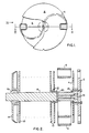
- Figures 1-3 A preferred embodiment of a nozzle barrier according to the present invention is illustrated in Figures 1-3, Figure 1 being a front elevational view, Figure 2 being a cross-sectional plan view taken along the line II-II of Figure 1, and Figure 3 being a simplified side elevational view taken in the direction of arrow III of Figure 1.
- the nozzle barrier includes a circular face plate 2 which, when the barrier is installed in a reactor nozzle, will face the interior of the reactor vessel. Behind face plate 2 there is disposed a first baffle plate 4 and behind baffle plate 4 there is provided an 5-shaped spring 6. Plates 2 and 4 provide a certain degree of thermal isolation between spring 6 and the interior of the reactor vessel sufficient to enable spring 6 to retain its spring properties when the vessel is at annealing temperatures.
- Spring 6 is provided at each end with a closed loop for engagement by a tool, to be described below, provided for inserting the barrier into, and extracting the barrier from, a pressure vessel nozzle.
- face plate 2 is provided with a pair of generally square holes and baffle plate 4 is provided with peripheral slots.
- the baffle further includes a mandrel 8 which connects together all of the other baffle components.
- These components include, in addition to those already identified, a plurality of additional circular baffle plates 10 which alternate, along the length of mandrel 8, with spacers 12, together with an end bell 14 at that end of the baffle which will be remote from the interior of the pressure vessel when the baffle is installed, and a nut 16 which screws onto a threaded portion at the rear end of mandrel 8 in order to secure all of the components together.
- mandrel 8 is provided with a longitudinal slot at its periphery (not shown) and plates 10 are provided with matching slots for receiving a key.
- Mandrel 8 is provided at its forward end with a central, axially extending slot for receiving the center of spring 6. After insertion of spring 6, a pin 18 is inserted into the central slot in order to hold spring 6 in place. The edge of spring 6 remote from pin 18 is provided with a notch which engages with a further pin 20 inserted through a radial bore in mandrel 8.
- mandrel 8 The forward end of mandrel 8 is further provided with a flanged portion having two tapped openings receiving bolts which hold face plate 2 in position on mandrel 8. Face plate 2 additionally serves to retain pin 18 in place so that pins 18 and 20 together maintain spring 6 in a fixed position along the axis of mandrel 8.
- spring 6 when spring 6 is in its unstressed state, shown in Figures 1-3, it projects radially beyond all of the other components of the barrier to an extent sufficient to securely retain the baffle in a pressure vessel nozzle. This assures that the baffle will not be displaced during reactor heat treatment, even when subjected to the force of water flowing through the nozzle during water drainage or filling of the pressure vessel.
- all of the baffle components except for spring 6 may be made of stainless steel, and spring 6 may be made of a high temperature resistant alloy of the type sold under the U.S. Trademark Inconel 718.
- end bell 14 is given a conical configuration in order to facilitate introduction of the baffle into a pressure vessel nozzle.
- the outer edge of face plate 2 is preferably contoured to match the contour of the nozzle end to be engaged by face plate 2.
- the entire surface of face plate 2 may, if desired, be contoured to precisely match the contour of the vessel wall surrounding the associated nozzle.
- the barrier assembly can be easily disassembled, without requiring cutting welds, in order to permit radioactive decontamination of its component parts.
- FIG 3 illustrates a siphon tube 24 provided for this purpose and attached to a bracket 26 of end bell 14 via a lug 28 and a screw 30 which permits tube 24 to pivot relative to bracket 26.
- siphon tube 24 is shown in the position which it assumes when the barrier is installed in a nozzle. Prior to installation, and while being lowered through the pressure vessel to the location of the nozzle, tube 24 is pivoted to hang downwardly. This reduces the largest horizontal dimension of the barrier assembly and thus facilitates its introduction via passages provided at the top of the reactor vessel. Additionally, this allows the siphon tube to fill with water as the barrier is being lowered through the vessel, thereby assuring performance of the subsequent siphoning action.
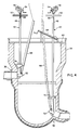
- FIG 4 is an elevational view showing a reactor pressure vessel 34 from which all reactor internals have been removed preparatory to heat treatment.
- One upper nozzle 36 and one lower nozzle 38 of pressure vessel 34 are shown, each nozzle being blocked by a thermal barrier of the type shown in Figures 1 - 3, with the thermal barrier in lower nozzle 38 being provided with a siphon tube.
- Each handling tool includes: a lifting shackle 46 via which the weight of the tool is supported by a sling; a tubular stalk 48 of square cross section; a T-handle 50; a tool head 52 carrying a latching mechanism; a crank assembly 54 containing a ratchet mechanism; and a shaft 56 housed within stalk 48 and connected for transmitting rotary movement from its associated crank assembly 54 to its associated tool head 52.
- Each tool head 52 includes a mechanism which releasably engages an associated nozzle barrier in order to introduce the barrier into an associated nozzle and subsequently extract the barrier therefrom.
- a suitable embodiment of this mechanism will be described in greater detail below.
- a work platform 60 having access openings is temporarily installed at the top of pressure vessel 34.
- vessel 34 will be filled with water to provide radiation shielding.
- the weight of the associated handling tool is primarily supported by a sling secured to shackle 46 and the tool is further guided by the operating personnel, with the aid of handle 50. Movement of a barrier into its associated nozzle may be further aided by an insertion fixture 64, which will be described in greater detail below.
- Removal of a barrier from its associated nozzle may be aided, if necessary, by an associated extraction tool composed essentially of: a long tubular body 66, 68 essentially constituting a lever; a pin located at the lower end of the tubular body to engage in a recess provided in the associated tool head 52; and a foot 72, 74 supported by the associated tubular body 66, 68 and arranged to rest against the interior wall of vessel 34 to provide a fulcrum about which tubular body 66, 68 can pivot.
- Each foot 72, 74 can be attached to its associated tubular body 66, 68, to permit a limited degree of pivotal movement to occur therebetween.
- the associated crank assembly 54 is operated to transmit rotary movement, via the associated shaft 56, to the mechanism.
- handling tool 40 is displaced parallel to that axis with the aid of a component of insertion fixture 64 which supports stalk 48, via a lug 76 fastened to stalk 48, and which is movable along a travel path parallel to the nozzle axis. Insertion fixture 64 can also aid in the extraction of the thermal barrier from nozzle 38.
- nozzle 36 has a horizontal axis, such an insertion fixture will, in most cases, not be required to guide tool 42 during insertion of a thermal barrier.
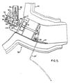
- FIG. 5 An embodiment of the mechanism disposed in each tool head 52 is shown in Figures 5 and 6, Figure 5 being a side elevational view showing tool head 52 in cross section and Figure 6 being a plan view with portions of the housing of tool head 52 removed.
- the mechanism in tool head 52 includes a shaft 80 supported at its ends by bearings installed in the tool head housing.
- Shaft 80 has a threaded portion 82 which engages a nut 84 mounted in the tool head housing so as to be fixed against rotation but to be movable parallel to the axis of shaft 80 as that shaft rotates.
- Fixed to shaft 80 is a bevel gear 86 which engages a bevel gear 88 attached to the lower end of shaft 56 in order to rotate therewith.
- tool head 52 includes a recess 90 for receiving the pin at the lower end of tubular body 66 ( Figure 4).
- nut 84 is pivotally attached to two lever arms 94 each of which is pivotally connected, at its end remote from nut 84 to a further lever arm 96 which is pivoted to the housing of tool head 52 and carries a finger 98 arranged to pass through one of the holes in nozzle barrier face plate 2 and the aligned slot in baffle plate 4 ( Figures 1 and 2) in order to engage a loop at one end of spring 6.
- fingers 98 are displaced toward one another in order to radially compress spring 6 and to grasp plate 2 via the square holes therein, and thus permit movement of the thermal barrier in the associated nozzle 38. Movement of nut 84 away from the thermal barrier causes fingers 98 to move away from one another, so that spring 6 is allowed to press radially against the walls of nozzle 38.
- Tool head 52 is further provided with a lever 102 which is pivotally mounted and spring biased toward the position shown in broken lines in Figure 6.
- lever 102 When tool head 52 is in engagement with the thermal barrier, i.e., fingers 98 are in position to act on spring 6, lever 102 is deflected, by contact with face plate 2, into the position shown in solid lines in Figure 6. In this position, the free end of lever 102 projects out of the tool head housing to provide a visual indication that the engagement position has been attained.
- Establishment of the engagement position is further aided by a positioning foot 104 which supports face plate 2 and maintains the correct barrier orientation when the tool head is in the engagement position.
- the end of shaft 80 which is directed away from the thermal barrier is provided with a drive part 106, such as a square stud, that may be directly engaged by a tool to rotate shaft 80 when the tool head is at a location above platform 60. This will permit the tool head to be engaged with or disengaged from a thermal barrier while tool head 52 is at an elevated position. If necessary, crank 54 can be disengaged from bevel gear 86 during such operation.
- the mechanism within tool head 52 is operated by the associated crank assembly 54.
- the ratchet mechanism in assembly 54 serves to maintain the assembly in the engaged position.
- Figure 5 additionally shows, in solid lines, the orientation of siphon tube 24 when the associated thermal barrier is inserted in nozzle 38.
- the broken line position 24′ represents that assumed by siphon tube 24 relative to the thermal barrier as the thermal barrier is being lowered through the pressure vessel to the position of the associated nozzle.
- siphon tube 24 can be pivoted into the orientation which it must assume when the thermal barrier is inserted into nozzle 38 by means of a lanyard secured to the outlet end of siphon tube 24, which is the lower end of the tube when in position 24′, which lanyard extends upwardly through pressure vessel 34 to the level of platform 60.
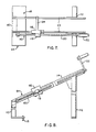
- Insertion fixture 64 is composed of two vertical posts 110 and 112 mounted on feet which rest on platform 60 and supporting two rails 114, each having a rectangular cross section. At least one foot is provided with positioning pins 115.
- a block 116 is provided with a rectangular passage through which one of the rails 114 extends, so that block 116 is supported by that rail 114.
- Block 116 carries a projecting part 118 provided with a threaded passage through which extends a threaded rod 120 supported at its ends by bearings secured to the one rail 114 and provided at one end with a crank 122 via which rod 120 can be manually rotated in order to advance projecting part 118, and thus block 116, along the one rail 114.
- Block 116 additionally carries a pin or rod 124 which rests upon the other rail 114 and constitutes the support for lug 76 ( Figure 4).
- crank 122 is rotated to move block 116, and thus pin 124, along the path defined by rails 114 in order to cause the barrier to move along the nozzle axis.
- Platform 60 is shown plan view in Figure 9.
- Platform 60 is constituted by a generally circular steel plate 130 provided with an array of access openings 132 for the introduction of barriers, handling tools and extraction tools. Each opening 132 is provided with a recessed ledge 134 for supporting a removable cover 136. Other openings shown in Figure 9 are provided for receiving alignment devices which are not of significance to the present invention.
- Plate 130 is additionally provided, at spaced locations about its periphery, with screws (not shown) for securing platform 60 in a desired position at the top of vessel 34. Openings 132 are arranged such that each opening is in line with one of the vessel nozzles into which a barrier is to be placed. When fixture 64 is placed on platform 60, pins 115 rest against the edge of an associated access opening 132 in plate 130 to accurately locate fixture 64.
- Each ledge 134 is recessed downwardly by a distance selected to conform to the thickness of the associated cover 136 so that when a cover 136 is in place, it defines, together with the upper surface of plate 130, a flat work surface.
- each cover 136 is provided with a group of screws 138 for fastening the cover to plate 130.
- each cover includes two tapped blind bores 140 for the attachment of mechanical handling devices to lift cover 136, and with two handles 142 for permitting manual lifting of the cover.
- each handle 142 is composed of a U-shaped part whose ends are welded to a horizontal bar located adjacent the bottom surface of cover 136. The legs of the U-shaped part extend through passages formed in cover 136, while the base of that part lies in a recessed region formed in the upper surface of cover 136. The center of this recessed region is provided with a groove which permits initial gripping of handle 142.
- Handle 142 is loosely mounted on cover 136 so that when handle 142 is lifted, the bar at the underside of cover 136 comes to bear against the lower surface of cover 136, whereupon the cover can be lifted. When not in use, handle 142 does not extend above the upper surface of cover 136, and thus does not present a hazard to workers standing on platform 60.
- All parts of platform 60 are preferably made of stainless steel.
- the reactor vessel can be annealed with the system disclosed in the above-cited copending U.S. application bearing U.S. Serial No. 368,456, using the heater unit assembly disclosed in the above-cited copending U.S. application bearing Serial No. 368,432.
Landscapes
- Physics & Mathematics (AREA)
- Engineering & Computer Science (AREA)
- Plasma & Fusion (AREA)
- General Engineering & Computer Science (AREA)
- High Energy & Nuclear Physics (AREA)
- Monitoring And Testing Of Nuclear Reactors (AREA)
- Nozzles (AREA)
Applications Claiming Priority (2)
| Application Number | Priority Date | Filing Date | Title |
|---|---|---|---|
| US368738 | 1982-04-15 | ||
| US36873889A | 1989-06-19 | 1989-06-19 |
Publications (2)
| Publication Number | Publication Date |
|---|---|
| EP0405080A2 true EP0405080A2 (de) | 1991-01-02 |
| EP0405080A3 EP0405080A3 (en) | 1991-09-25 |
Family
ID=23452527
Family Applications (1)
| Application Number | Title | Priority Date | Filing Date |
|---|---|---|---|
| EP19900107325 Withdrawn EP0405080A3 (en) | 1989-06-19 | 1990-04-18 | Reactor vessel nozzle thermal barrier |
Country Status (2)
| Country | Link |
|---|---|
| EP (1) | EP0405080A3 (de) |
| JP (1) | JPH0335199A (de) |
Families Citing this family (1)
| Publication number | Priority date | Publication date | Assignee | Title |
|---|---|---|---|---|
| JP3098455B2 (ja) | 1997-05-14 | 2000-10-16 | 邦彦 小池 | 携帯電話機 |
Family Cites Families (6)
| Publication number | Priority date | Publication date | Assignee | Title |
|---|---|---|---|---|
| FR2289033A1 (fr) * | 1974-09-06 | 1976-05-21 | Commissariat Energie Atomique | Dispositif de calorifugeage de surfaces horizontales de fermeture pour reacteur nucleaire refroidi par metal liquide |
| DE2637751A1 (de) * | 1976-08-21 | 1978-02-23 | Leybold Heraeus Gmbh & Co Kg | Schliessarmatur und montageglocke |
| DE2820442C2 (de) * | 1978-05-10 | 1987-02-12 | Kraftwerk Union AG, 4330 Mülheim | Verfahren und Vorrichtung zur Wärmebehandlung von Wandpartien an der Innenseite des zylindrischen Mantels eines Reaktordruckbehälters |
| DE2851925C2 (de) * | 1978-11-30 | 1982-03-04 | Kraftwerk Union AG, 4330 Mülheim | Wärmebehandlungs-Vorrichtung zur Verlängerung der Lebensdauer eines Druckbehälters, insbesondere eines Reaktor-Druckbehälters |
| DE3228802C2 (de) * | 1982-08-02 | 1986-08-28 | Kraftwerk Union AG, 4330 Mülheim | De- und remontable Abdichteinrichtung und ein Verfahren zur Vorbereitung der Abdichtung von Rohrleitungen, insbesondere der Hauptkühlmittelstutzen eines Reaktordruckbehälters |
| GB8626237D0 (en) * | 1986-11-03 | 1986-12-03 | Nat Nuclear Corp Ltd | Fluid flow-restricting sealsbaffles |
-
1990
- 1990-04-18 EP EP19900107325 patent/EP0405080A3/en not_active Withdrawn
- 1990-06-19 JP JP2161151A patent/JPH0335199A/ja active Pending
Also Published As
| Publication number | Publication date |
|---|---|
| JPH0335199A (ja) | 1991-02-15 |
| EP0405080A3 (en) | 1991-09-25 |
Similar Documents
| Publication | Publication Date | Title |
|---|---|---|
| KR910003289B1 (ko) | 핵연료 집합체 처리장치 및 방법 | |
| JP2008216246A (ja) | 核燃料集合体内で燃料棒を位置合せしかつ操作するためのシステム | |
| US5377239A (en) | BWR control rod handling tooling & method | |
| KR900009108B1 (ko) | 가압수형 원자로의 안내관의 안내핀 교체방법 및 장치 | |
| EP1209692B1 (de) | Modulartige vorrichtung und verfahren zur unterwasserreperatur | |
| CN109406207B (zh) | 一种放射性废液贮罐放射性沉积物取样系统及其使用方法 | |
| KR940010228B1 (ko) | 방사된 핵연료 조립체로부터 클립을 제거하는 장치 | |
| US5070589A (en) | Process for servicing a jet pump hold down beam in a nuclear reactor | |
| JPS582633B2 (ja) | 原子炉の案内シンブル付き燃料集合体の把持装置 | |
| US4995158A (en) | Apparatus for servicing a jet pump hold down beam in a nuclear reactor | |
| EP0405080A2 (de) | Hitzesperre für Reaktorbehälter-Rohrstutzen | |
| JP7333797B2 (ja) | 核燃料集合体に対して介入を実施するためのデバイス | |
| US4590671A (en) | Tool for removing split pin remnants from a nuclear reactor vessel | |
| US6082393A (en) | Emergency shutoff valve exerciser for steam turbine and methods for installing and operating same | |
| US5069861A (en) | Apparatus for the remote unscrewing and extraction of an assembly screw | |
| JPS61246697A (ja) | 加圧水型原子炉における中性子束測定装置の案内管をクリ−ニングする装置 | |
| US5098644A (en) | Apparatus for consolidation of spent nuclear fuel rods | |
| CN108682464A (zh) | 百万千瓦级核电厂乏燃料水池扩容方法 | |
| EP0189718B1 (de) | Aufhängungsanordnung und Verfahren für den Manipulationsstab eines Kontrollbündels im Kernreaktor | |
| EP0263336A2 (de) | Wiederzusammenbau- und Reparatursystem für Kernbrennstabbündel | |
| EP0327055B1 (de) | Kernbrennelement-Handhabungsvorrichtung | |
| CN116665937B (zh) | 一种燃料组件修复的装置及方法 | |
| US5689537A (en) | Jet pump beam tensioner | |
| US4986955A (en) | Device for removing peripheral fuel rods from a fuel assembly of a nuclear reactor | |
| KR101776106B1 (ko) | 칼란드리아 내부 구조물 검사장비의 낙하방지장치 |
Legal Events
| Date | Code | Title | Description |
|---|---|---|---|
| PUAI | Public reference made under article 153(3) epc to a published international application that has entered the european phase |
Free format text: ORIGINAL CODE: 0009012 |
|
| AK | Designated contracting states |
Kind code of ref document: A2 Designated state(s): BE DE ES FR IT |
|
| RTI1 | Title (correction) | ||
| PUAL | Search report despatched |
Free format text: ORIGINAL CODE: 0009013 |
|
| AK | Designated contracting states |
Kind code of ref document: A3 Designated state(s): BE DE ES FR IT |
|
| RHK1 | Main classification (correction) |
Ipc: G21C 13/067 |
|
| STAA | Information on the status of an ep patent application or granted ep patent |
Free format text: STATUS: THE APPLICATION IS DEEMED TO BE WITHDRAWN |
|
| 18D | Application deemed to be withdrawn |
Effective date: 19920326 |