EP0404418B1 - Bilderzeugungsgerät - Google Patents
Bilderzeugungsgerät Download PDFInfo
- Publication number
- EP0404418B1 EP0404418B1 EP90306349A EP90306349A EP0404418B1 EP 0404418 B1 EP0404418 B1 EP 0404418B1 EP 90306349 A EP90306349 A EP 90306349A EP 90306349 A EP90306349 A EP 90306349A EP 0404418 B1 EP0404418 B1 EP 0404418B1
- Authority
- EP
- European Patent Office
- Prior art keywords
- paper
- image
- transfer paper
- feed roller
- image forming
- Prior art date
- Legal status (The legal status is an assumption and is not a legal conclusion. Google has not performed a legal analysis and makes no representation as to the accuracy of the status listed.)
- Expired - Lifetime
Links
- 239000011521 glass Substances 0.000 description 19
- 230000003287 optical effect Effects 0.000 description 13
- 238000010276 construction Methods 0.000 description 10
- 238000004140 cleaning Methods 0.000 description 4
- 238000012423 maintenance Methods 0.000 description 4
- 238000010586 diagram Methods 0.000 description 3
- 241000149947 Coronarchaica corona Species 0.000 description 2
Images


Classifications
-
- G—PHYSICS
- G03—PHOTOGRAPHY; CINEMATOGRAPHY; ANALOGOUS TECHNIQUES USING WAVES OTHER THAN OPTICAL WAVES; ELECTROGRAPHY; HOLOGRAPHY
- G03G—ELECTROGRAPHY; ELECTROPHOTOGRAPHY; MAGNETOGRAPHY
- G03G15/00—Apparatus for electrographic processes using a charge pattern
- G03G15/65—Apparatus which relate to the handling of copy material
- G03G15/6555—Handling of sheet copy material taking place in a specific part of the copy material feeding path
- G03G15/6558—Feeding path after the copy sheet preparation and up to the transfer point, e.g. registering; Deskewing; Correct timing of sheet feeding to the transfer point
- G03G15/6561—Feeding path after the copy sheet preparation and up to the transfer point, e.g. registering; Deskewing; Correct timing of sheet feeding to the transfer point for sheet registration
- G03G15/6564—Feeding path after the copy sheet preparation and up to the transfer point, e.g. registering; Deskewing; Correct timing of sheet feeding to the transfer point for sheet registration with correct timing of sheet feeding
-
- G—PHYSICS
- G03—PHOTOGRAPHY; CINEMATOGRAPHY; ANALOGOUS TECHNIQUES USING WAVES OTHER THAN OPTICAL WAVES; ELECTROGRAPHY; HOLOGRAPHY
- G03G—ELECTROGRAPHY; ELECTROPHOTOGRAPHY; MAGNETOGRAPHY
- G03G2215/00—Apparatus for electrophotographic processes
- G03G2215/00362—Apparatus for electrophotographic processes relating to the copy medium handling
- G03G2215/00367—The feeding path segment where particular handling of the copy medium occurs, segments being adjacent and non-overlapping. Each segment is identified by the most downstream point in the segment, so that for instance the segment labelled "Fixing device" is referring to the path between the "Transfer device" and the "Fixing device"
- G03G2215/00379—Copy medium holder
- G03G2215/00383—Cassette
-
- G—PHYSICS
- G03—PHOTOGRAPHY; CINEMATOGRAPHY; ANALOGOUS TECHNIQUES USING WAVES OTHER THAN OPTICAL WAVES; ELECTROGRAPHY; HOLOGRAPHY
- G03G—ELECTROGRAPHY; ELECTROPHOTOGRAPHY; MAGNETOGRAPHY
- G03G2215/00—Apparatus for electrophotographic processes
- G03G2215/00362—Apparatus for electrophotographic processes relating to the copy medium handling
- G03G2215/00367—The feeding path segment where particular handling of the copy medium occurs, segments being adjacent and non-overlapping. Each segment is identified by the most downstream point in the segment, so that for instance the segment labelled "Fixing device" is referring to the path between the "Transfer device" and the "Fixing device"
- G03G2215/00405—Registration device
-
- G—PHYSICS
- G03—PHOTOGRAPHY; CINEMATOGRAPHY; ANALOGOUS TECHNIQUES USING WAVES OTHER THAN OPTICAL WAVES; ELECTROGRAPHY; HOLOGRAPHY
- G03G—ELECTROGRAPHY; ELECTROPHOTOGRAPHY; MAGNETOGRAPHY
- G03G2215/00—Apparatus for electrophotographic processes
- G03G2215/00362—Apparatus for electrophotographic processes relating to the copy medium handling
- G03G2215/00443—Copy medium
- G03G2215/00447—Plural types handled
-
- G—PHYSICS
- G03—PHOTOGRAPHY; CINEMATOGRAPHY; ANALOGOUS TECHNIQUES USING WAVES OTHER THAN OPTICAL WAVES; ELECTROGRAPHY; HOLOGRAPHY
- G03G—ELECTROGRAPHY; ELECTROPHOTOGRAPHY; MAGNETOGRAPHY
- G03G2215/00—Apparatus for electrophotographic processes
- G03G2215/00362—Apparatus for electrophotographic processes relating to the copy medium handling
- G03G2215/00535—Stable handling of copy medium
- G03G2215/00556—Control of copy medium feeding
-
- G—PHYSICS
- G03—PHOTOGRAPHY; CINEMATOGRAPHY; ANALOGOUS TECHNIQUES USING WAVES OTHER THAN OPTICAL WAVES; ELECTROGRAPHY; HOLOGRAPHY
- G03G—ELECTROGRAPHY; ELECTROPHOTOGRAPHY; MAGNETOGRAPHY
- G03G2215/00—Apparatus for electrophotographic processes
- G03G2215/00362—Apparatus for electrophotographic processes relating to the copy medium handling
- G03G2215/00535—Stable handling of copy medium
- G03G2215/00603—Control of other part of the apparatus according to the state of copy medium feeding
Definitions
- This invention relates to an image forming apparatus which is equipped with storage means for storing a recording medium, and feed means including first and second paper feed rollers, said first paper feed roller delivering the recording medium from the storage means and abutting it to said second paper feed roller and said second paper feed roller feeding the abutted recording medium to an image forming unit.
- FIG. 6 is a structural view of an electrophotographic reproducing apparatus as a prior art example.
- a document glass plate 1 which is made of transparent glass and on which a document D is to be placed is disposed at the center of the upper portion of a reproducing apparatus main body and a scale plate 2 for designating the placement position in accordance with the size of the document D is disposed at the left end of the document glass plate 1.
- a document cover 3 capable of covering the document D placed on the document glass plate 1 is disposed at the upper part of this plate 1 in such a manner as to be capable of turning down forwardly.
- the document D is placed on the document glass plate 1 in match with the scale designated by the scale plate 2 and when covered with the document cover 3, its movement is restricted.
- a first mirror unit 6 equipped with an exposure lamp 4 and a first mirror 5 is disposed below the document glass plate 1 and inside the reproducing apparatus main body in such a manner as to be capable of moving linearly to the right and left in Fig. 6 in parallel with the document glass plate 1, and capable of scanning the full surface of the document D.
- a second mirror unit 9 formed by integrating second and third mirrors 7 and 8 can linearly move to the right and left in Fig. 6 and in parallel with the document glass plate 1 at the speed which is the half of the first mirror unit 6 in such a manner as to keep a predetermined optical path length.
- a main lens 10 is the lens to which the reflected rays of light from the document D on the document glass plate 1 are incident after being reflected by the first, second and third mirrors 5, 7, 8, and the rays of light leaving this main lens 10 are incident into a photosensitive drum 12 as an image retainer through a fourth mirror 11 and through a slit 13.
- These first and second mirror units 6 and 9 are driven by an optical system driving motor not shown in the drawing.
- a charging electrode 14 charges uniformly the photosensitive drum 12. Accordingly, electrostatic latent images are formed sequentially on the photosensitive drum 12 rotating clockwise in Fig. 4 due to the incidence of rays of light from the optical system described above.
- a developing device 15 converts the electrostatic latent image on this photosensitive drum 12 to a visible toner image.
- a paper feeder for feeding transfer paper comprises a paper cassette 16 for storing transfer paper (recording medium) P, a first paper feed roller 17 for delivering one by one this transfer paper P from the paper cassette 16, a second paper feed roller 18 for feeding delivered transfer paper P to the photosensitive drum 12 side, and guide plates 19 and 20 disposed between the paper cassette 16 and the second paper feed roller 18 and between the second paper feed roller 18 and a transfer electrode which will be described later.
- transfer paper P inside the paper cassette 16 is delivered by the first paper feed roller 17 and is abutted against the second paper feed roller 18 while being guided by the guide plate 19.
- the second paper feed roller 18 is driven by a paper feed timing signal which brings the tip of the toner image on the photosensitive drum 12 into conformity with the tip of transfer paper P.
- a transfer electrode 21 transfers the toner image on the photosensitive drum 12 onto transfer paper P and a separating electrode 22 separates transfer paper P from the photosensitive drum 12.
- Transfer paper P separated there is sent to a fixing device 24 through transfer paper conveyor means 23, is subjected to fusion-fixing by a heat-fixing roller and a press roller and is thereafter discharged by a paper discharge roller 25 onto a paper tray 26.
- These first paper feed roller 17, second paper feed roller 18, photosensitive drum 12 and paper discharge roller 25 are driven by a paper feed system driving motor which is not shown in the drawing.
- a cleaning/charge eliminating electrode 28 for effecting A.C. corona discharge is disposed at its pre-stage.
- a charge eliminating unit 29 for erasing the charge of the non-image portions is disposed at the post-stage of the charging electrode 14 so as to prevent the toner from attaching to the non-image portions and in such a manner as to face the photosensitive drum 12.
- reference numerals 30 and 31 represent a precharge exposure unit and an exposure unit before transfer, respectively.
- the second paper feed roller 18 is driven by the paper feed timing signal such that the tip of the toner image on the photosensitive drum 12 is in conformity with the tip of transfer paper P.
- This timing signal is generated from a timing sensor, not shown, when the first mirror unit 6 reaches a predetermined position.
- the timing signal is generated at the same timing for both transfer paper P which is supplied from the paper cassette 16 of the upper stage and transfer paper P which is supplied from the paper cassette 16 of the lower stage.
- the paper feed path (the route from each paper cassette 16 to the second paper feed roller 18) is different between transfer paper P supplied from the paper cassette 16 of the upper stage and transfer paper P supplied from the paper cassette 16 of the lower stage. Since transfer paper P is fed while it keeps sliding contact with the paper feed path, a delicate sliding difference occurs on the second paper feed roller 18 depending on the level of the frictional resistance to transfer paper P and therefore the problems occurs in that the tip of the toner image on the photosensitive drum 12 does not coincide with the tip of transfer paper P.
- the paper feed path (the route from each paper cassette 16 to the second paper feed roller 18) is different between transfer paper P supplied from the paper cassette 16 of the upper stage and transfer paper P supplied from the paper cassette 16 of the lower stage. Since transfer paper P is supplied while keeping sliding contact with the paper feed path, a delicate sliding difference occurs at the second paper feed roller 18 depending on the level of the frictional resistance to transfer paper P and a difference of the paper feed speed occurs depending on the position of the paper feed cassette 16.
- the length of the image transferred to transfer paper P of an A3 size of an intermediate stage in the paper feed direction becomes shorter by 0.3% in comparison with transfer paper P of the A3 size of the paper cassettte of the upper stage.
- the length of the image transferred to transfer paper of an A4R size of the paper cassette of the upper stage in the paper feed direction becomes longer by 0.1%.
- the document US-A-4,260,241 describes image forming apparatus comprising: scanning means for scanning a document; an image forming unit responsive to the scanning means for forming an image of said scanned document and operable to form a recording of the image on recording paper; common paper feed roller means for feeding a sheet of recording paper to said unit for recordal of the image thereon; first and second recording paper storage means each associated with paper supply roller means for supplying individual sheets of the recording paper from that storage means and for delivering the supplied sheet to abut the common paper feed roller means; guide means defining paper sheet guide paths upto said common roller means and between said common roller means and said image forming unit; and control means for controlling operation of the scanning means.
- the present invention has the features mentioned above and is characterized by: selection means operable to select the first or second recording paper storage means and to provide a signal representative of the selected storage means to said control means; and said control means including variable drive speed means responsive to said signal to alter the drive speed of said scanning means to cause said drive speed to be in the same degree of conformity with the feed speed of said common paper feed roller means irrespective of whether a recording sheet is being supplied from said first or second said recording paper storage means.
- the present invention thereby identifies and takes into account the slight sliding differences that occur in practice when a sheet of recording paper is fed by the common paper feed roller means along the guide means respectively from the first and from the second recording paper storage means.
- a document glass plate 41 on which a document D is placed and which is made of transparent glass is disposed at the center on a reproducing apparatus main body and a scale plate 42 for designating the placement position of the document D in accordance with its size is disposed at the left end of the document glass plate 41.
- a document cover 43 for covering the document D placed on the document glass plate 41 is disposed at the part of the glass plate 41, in such a manner as to be capable of turning down forwardly.
- the document D is placed on the document glass plate 41 in accordance with the scale designated by the scale plate 42 and when covered with the document cover 43, its movement is restricted.
- a first mirror unit 46 equipped with an exposure lamp 44 and a first mirror 45 is disposed below the document glass plate 41 and inside the reproducing apparatus main body in parallel with the document glass plate 41 and in such a manner as to be capable of moving linearly to the right and left in Fig. 2 and to scan the full surface of the document D.
- a second mirror unit 49 formed by integrating second and third mirrors 47 and 48 is allowed to move linearly to the right and left in Fig. 2 and in parallel with the document glass plate 41 at the speed of 1/2 of the first mirror unit 46.
- These mirror units 46 and 49 are driven by an optical system motor 100 and this motor is in turn driven variably by a driving circuit 101 of a PLL control system.
- a main lens 50 is the lens to which the reflected rays of light from the document D on the document glass plate 41 are incident after being reflected by the first, second and third mirrors 45, 47, 48, and the rays of light leaving this main lens 50 are incident into a photosensitive drum 52 as an image retainer through a fourth mirror 51 and a slit 53.
- a charging electrode 54 charges uniformly the photosensitive drum 52. Accordingly, electrostatic latent images are formed sequentially on the photosensitive drum 52 rotating clockwise in Fig. 2 due to the incidence of rays of light from the optical system described above.
- a developing device 55 converts the electrostatic latent image on the photosensitive drum 52 to a visible toner image.
- a paper feed device for feeding transfer paper P consists of paper cassettes 56 (two cassettes are shown in Fig. 2) for storing transfer paper P (recording medium), a first paper feed roller 57 for delivering one by one transfer paper P from the paper cassette 56, a second paper feed roller 58 for feeding the delivered transfer paper P to the photosensitive drum 52 side, and guide plates 59 and 60 disposed between the paper cassette 56 and the second paper feed roller 58 and between the second paper feed roller 58 and a later-appearing transfer electrode.
- transfer paper P inside the selected paper cassette 56 is delivered by the first paper feed roller 57, is guided by the guide plate 59 and then abutted against the second paper feed roller 58.
- the second paper feed roller 58 is driven by a paper feed timing signal from a control unit 76 so that the tip of the toner image on the photosensitive drum 52 is in comformity with the tip of transfer paper P.
- a transfer electrode 61 transfers the toner image on the photosensitive drum 52 to transfer paper P and a separating electrode 62 separates transfer paper P from the photosensitive drum 52.
- Transfer paper P separated here is sent to a fixing device 64 through transfer paper conveyor means 63, is subjected to fusion-fixing by a heat fixing roller and a press roller and is thereafter discharged onto a tray 66 by a paper discharge roller 65.
- the toner remaining on the photosensitive drum 52 is removed by a cleaning device 67.
- a cleaning/charge eliminating electrode 68 for effecting A.C. corona discharge is disposed at a prestage.
- a charge eliminating unit 69 for eliminating the charge of non-image portions by light is disposed at the post-stage of the charge electrode 54 in such a manner as to face the photosensitive drum 52, in order to prevent adhesion of the toner to the non-image portions.
- reference numerals 70 and 71 represent a precharge exposure unit and an exposure unit before transfer, respectively.
- reference numeral 72 represents a timing sensor responsive to the arrival of the first mirror unit 46 at a predetermined position and reference numeral 73 represents a clutch of a solenoid driving type which transmits or cuts off the driving force to the second paper feed roller 58.
- Reference numeral 74 represents a transfer paper size detector for detecting the size of transfer paper P stored in the paper cassette 56. Image forming apparatus including such a size detector 74 alone is outside the scope of the present invention.
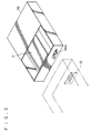
- the transfer paper size detector 74 will be explained with reference to Fig. 3.
- maximum four protuberances 56a corresponding to the sizes of transfer paper P are fitted to the tip surface of the paper cassette 56.
- four microswitches 75 are disposed on the apparatus side. When the paper cassette 56 is set to the apparatus, the protuberances 56a push the microswitches 75. The size of transfer paper P is detected by the kind of this pushed microswitch 75.
- reference numeral 76 represents a control unit of the reproducing apparatus.
- This control unit 76 is provided with a non-volatile RAM 77, into which the driving timing data of the second paper feed roller 58 for each size of transfer paper P, that are determined in advance, are written and with a CPU 78 which reads out the data written into the non-volatile RAM 77 and sets the data to a timer IC 79.
- Reference numeral 80 represents a driving circuit for driving a solenoid of a clutch 73.
- Predetermined data which permit the tip of the toner image on the photosensitive drum 52 to become coincident with the tip of transfer paper P fed are written into the non-volatile RAM 77 for each size of transfer paper P at the time of assembly or maintenance in consideration of the load of the frictional resistance of the guide plates 59, 60, and the like.
- control unit 76 receives the size data of transfer paper P stored in the paper cassette 56 from the transfer paper size detector 74.
- CPU 78 selects the data corresponding to the size of transfer paper P from the non-volatile RAM 77 and sets them to the timer IC 79.
- the timing sensor 72 responds to this arrival and provides the timing signal to the timer IC 79.
- the timer IC 79 actuates the driving circuit 80 on the basis of the set data.
- the driving circuit 80 operates, the solenoid of the clutch 73 operates and the second paper feed roller 58 feeds transfer paper P to the photosensitive drum 52.
- the present invention is applied to an image forming apparatus having a plurality of sets of cassettes.
- data corresponding to (number of stages of cassettes X sizes of transfer paper P) are recorded into the non-volatile RAM 77, and the control unit 76 receives the position data of the selected paper cassette 56 and the size data of transfer paper P and selects the corresponding data from the non-volatile RAM 77.
- the present invention is not particularly limited to the reproducing apparatus but can of course be applied to other image forming apparatuses such as a laser beam printer.
- the driving timing data of the second paper feed roller 58 that are determined in advance depending on the position of the paper cassette 56 are written into the non-volatile RAM 77 of the control unit 76 of the reproducing apparatus and CPU 78 reads out the data written into the non-volatile RAM 77 and sets them to the timer IC 79.
- the apparatus has cassette selection means (not shown) including a switch which is disposed on the main panel for selecting whether transfer paper P of the upper paper cassette 56 or transfer paper P of the lower cassette 56 is to be fed.
- the predetermined data which permit the feed of transfer paper P to the photosensitive drum 52 at the same timing irrespective of the position of the paper cassette 56 are written into the non-volatile RAM 77 at the time of assembly or maintenance in consideration of the load of the frictional resistance of the guide plates 59, 60, and the like.
- the operator decides whether transfer paper P of the upper paper cassette 56 or transfer paper P of the lower paper cassette 56 is to be used, by use of the cassette selection means.
- the data of the selected paper cassette 56 is received by CPU 78 and CPU 78 selects the data corresponding to the selected paper cassette 57 from the non-volatile RAM 77 and sets them to the timer IC 79.
- the timing sensor 72 operates in response thereto and provides the timing signal to the timer CI 79.
- the timer IC 79 actuates the driving circuit 80 on the basis of the set data.
- the driving circuit 80 operates, the solenoid of the clutch 73 operates and the second paper feed roller 58 feeds the transfer paper P to the photo-sensitive drum 52.
- transfer paper P can be supplied to the photosensitive drum at the same timing irrespective of the set position of the paper cassette 56.
- variance of timing can be eliminated by writing into the non-volatile RAM those data which take into consideration the frictional resistance of the feed path from the stacker to the photosensitive drum.
- control means for driving the second paper feed roller at the timing at which the tip of the image in the image forming unit is in conformity with the tip of the recording medium is disposed for each of a plurality of storage means, it is possible to accomplish the image forming apparatus capable of supplying the recording medium to the image forming unit at the same timing irrespective of the position of the storage means of the recording medium.
- the driving speed data of the scanning system which brings the driving speed of the scanning system into conformity with the driving speed of the feed system for each size of transfer paper P are written into the non-volatile RAM 77 at the time of its assembly or maintenance in consideration of the load of the frictional resistance of the guide plates 59, 60, and the like.
- control unit 76 receives the size data of transfer paper P stored in the paper cassette 56 from the transfer paper size detector 74.
- CPU 78 selects the data corresponding to the size of transfer paper P from the non-volatile RAM 77 and sets it to the driving circuit 101.
- the optical system driving motor 100 is then driven on the basis of this data.
- the driving speed of the feed system can be brought into conformity with the driving speed of the optical system irrespective of the size of transfer paper P. Accordingly, no difference occurs between the length of the image of the document D in the feed direction obtained by scanning and the length of the image in the feed direction transferred onto transfer paper P.
- this apparatus since this apparatus includes the control means for controlling the scan-driving means for each size of the recording medium so that the feed speed of the feed means is in conformity with the driving speed of the scan-driving means, it is possible to accomplish the image forming apparatus which does not generate the difference of the driving speed between the feed system and the scanning system irrespective of the size of the recording medium.
- the driving speed data of the optical system driving motor 100 determined in advance depending on the position of the paper cassette 56 are written into the non-volatile RAM 77 of the control unit 76, and CPU 78 reads out the data written into the non-volatile RAM 77 and sets them to the driving circuit 101.
- reference numeral 81 represents cassette selection means which includes a switch disposed on the main panel and selects whether transfer paper P of the upper paper cassette 56 or transfer paper P of the lower paper cassette 56 is to be supplied.
- the driving data of the optical system driving motor 100 are written into the non-volatile RAM 77 at the time of its assembly or maintenance so that the driving speed of the scanning system is in confirmity with that of the feed system irrespective of the position of the paper cassette 56, in consideration of the load of the frictional resistance of the guide plates 59, 60, and the like.
- the operator decides whether transfer paper P of the upper cassette 56 or transfer paper P of the lower paper cassette 56 is to be used by use of the cassette selection means 81.
- the date of the selected paper cassette 56 are sent to CPU 78 and CPU 78 selected the data corresponding to the selected paper cassette 56 from the non-volatile RAM 77 and sets it to the driving circuit 101.
- the optical system driving motor 100 is driven on the basis of this data.
- the driving speed of the feed system can be brought into conformity with that of the optical system irrespective of the set position of the paper cassette 56. Accordingly, no difference occurs between the length of the image of the document D in the feed direction obtained by scanning and the length of the image in the feed direction transferred onto transfer paper P.
- the present invention is not limited particularly to the reproducing apparatus but can of course be applied to other image forming apparatuses such as a laser beam printer.
- control means for controlling the driving means so that the feed speed of the feed means is in conformity with the driving speed of the scan driving means is disposed for each of a plurality of storage means. Therefore, it is possible to accomplish an image forming apparatus which does not generate the difference of the driving speed between the feed system and the scanning system irrespective of the positions of the storage means of the recording medium.
Landscapes
- Physics & Mathematics (AREA)
- General Physics & Mathematics (AREA)
- Paper Feeding For Electrophotography (AREA)
- Sheets, Magazines, And Separation Thereof (AREA)
- Control Or Security For Electrophotography (AREA)
Claims (1)
- Abbildungsgerät mit:
Abtastmitteln (100) zum Abtasten eines Originals;
einer auf die Abtastmittel reagierenden Abbildungseinheit (52) zum Abbilden des besagten abgetasteten Originals, die zum Bilden einer Aufzeichnung des Abbilds auf Aufzeichungspapier betätigt werden kann;
gemeinsamen Papiervorschubrollenmitteln (58) zum Vorschieben eines Blattes Aufzeichnungspapier zur besagten Einheit (52) zur Aufzeichnung des Abbilds darauf;
ersten und zweiten Aufzeichnungspapiervorratsmitteln (56), die jeweils mit Papierzufuhrrollenmitteln (57) zur Zuführung von Einzelblättern des Aufzeichnungspapiers aus diesen Vorratsmitteln und zur Abgabe des zugeführten Blattes zum Anstoßen an die gemeinsamen Papiervorschubrollenmittel (58) verbunden sind;
Führungsmitteln (59, 60), die Papierblattführungs- wege bis zu den besagten gemeinsamen Rollenmitteln (58) und zwischen den besagten gemeinsamen Rollenmitteln und der besagten Abbildungseinheit (52) definieren; und
Steuermitteln (76) zum Steuern der Funktion der Abtastmittel (100);
gekennzeichnet durch
Auswahlmittel, die zum Auswählen der ersten oder zweiten Aufzeichnungspapiervorratsmittel (56) und zum Bereitstellen eines die ausgewählten Vorratsmittel darstellenden Signals für die besagten Steuermittel betätigt werden können; und
wobei die besagten Steuermittel (76) auf das besagte Signal reagierende variable Antriebsgeschwindigkeitsmittel (101) zur Veränderung der Antriebsgeschwindigkeit der besagten Abtastmittel (100) enthalten, um zu bewirken, daß die besagte Antriebsgeschwindigkeit denselben Konformitätsgrad zu der Vorschubgeschwindigkeit der besagten gemeinsamen Papiervorschubrollenmittel (58) besitzt, ungeachtet dessen, ob ein Aufzeichnungsblatt von den besagten ersten oder zweiten besagten Aufzeichnungspapiervorratsmitteln (56) zugeführt wird.
Applications Claiming Priority (8)
| Application Number | Priority Date | Filing Date | Title |
|---|---|---|---|
| JP159086/89 | 1989-06-21 | ||
| JP1159086A JPH0324565A (ja) | 1989-06-21 | 1989-06-21 | 像形成装置 |
| JP1167890A JPH0331143A (ja) | 1989-06-29 | 1989-06-29 | 像形成装置 |
| JP167890/89 | 1989-06-29 | ||
| JP177591/89 | 1989-07-10 | ||
| JP177590/89 | 1989-07-10 | ||
| JP1177590A JP2752169B2 (ja) | 1989-07-10 | 1989-07-10 | 像形成装置 |
| JP1177591A JPH0342683A (ja) | 1989-07-10 | 1989-07-10 | 像形成装置 |
Publications (3)
| Publication Number | Publication Date |
|---|---|
| EP0404418A2 EP0404418A2 (de) | 1990-12-27 |
| EP0404418A3 EP0404418A3 (de) | 1991-07-03 |
| EP0404418B1 true EP0404418B1 (de) | 1994-12-21 |
Family
ID=27473592
Family Applications (1)
| Application Number | Title | Priority Date | Filing Date |
|---|---|---|---|
| EP90306349A Expired - Lifetime EP0404418B1 (de) | 1989-06-21 | 1990-06-11 | Bilderzeugungsgerät |
Country Status (2)
| Country | Link |
|---|---|
| EP (1) | EP0404418B1 (de) |
| DE (1) | DE69015262T2 (de) |
Families Citing this family (1)
| Publication number | Priority date | Publication date | Assignee | Title |
|---|---|---|---|---|
| JPH04327444A (ja) * | 1991-04-26 | 1992-11-17 | Sanyo Electric Co Ltd | 画像形成装置 |
Citations (1)
| Publication number | Priority date | Publication date | Assignee | Title |
|---|---|---|---|---|
| DE3320734A1 (de) * | 1982-06-10 | 1983-12-15 | Konishiroku Photo Industry Co., Ltd., Tokyo | Papierzufuhreinrichtung einer kopiervorrichtung |
Family Cites Families (6)
| Publication number | Priority date | Publication date | Assignee | Title |
|---|---|---|---|---|
| JPS5911905B2 (ja) * | 1975-12-18 | 1984-03-19 | キヤノン株式会社 | カヘンバイフクシヤキ |
| US4260241A (en) * | 1978-05-17 | 1981-04-07 | Canon Kabushiki Kaisha | Copying apparatus |
| JPS5779966A (en) * | 1980-11-06 | 1982-05-19 | Ricoh Co Ltd | Control device for number of copying sheet |
| DE3220734A1 (de) * | 1982-06-02 | 1983-12-08 | Siemens AG, 1000 Berlin und 8000 München | Verfahren fuer eine fernsprechstation mit zwoelfteiliger waehltastatur zuzueglich sondertasten fuer teilnehmerdienste |
| JPS59198475A (ja) * | 1983-04-26 | 1984-11-10 | Toshiba Corp | 像形成装置 |
| US4809050A (en) * | 1986-09-11 | 1989-02-28 | Minolta Camera Kabushiki Kaisha | Copying machine for forming an image of a document at various magnifications |
-
1990
- 1990-06-11 EP EP90306349A patent/EP0404418B1/de not_active Expired - Lifetime
- 1990-06-11 DE DE1990615262 patent/DE69015262T2/de not_active Expired - Fee Related
Patent Citations (1)
| Publication number | Priority date | Publication date | Assignee | Title |
|---|---|---|---|---|
| DE3320734A1 (de) * | 1982-06-10 | 1983-12-15 | Konishiroku Photo Industry Co., Ltd., Tokyo | Papierzufuhreinrichtung einer kopiervorrichtung |
Also Published As
| Publication number | Publication date |
|---|---|
| DE69015262D1 (de) | 1995-02-02 |
| EP0404418A3 (de) | 1991-07-03 |
| EP0404418A2 (de) | 1990-12-27 |
| DE69015262T2 (de) | 1995-06-08 |
Similar Documents
| Publication | Publication Date | Title |
|---|---|---|
| EP0997788B1 (de) | Blattfördergerät und Bilderzeugungsgerät hiermit | |
| US4192607A (en) | Apparatus for selectively copying documents from two different document feeders | |
| US4279504A (en) | Copier and multifunction paper cassette | |
| US7654523B2 (en) | Image forming device and sheet transport device | |
| US5355206A (en) | Copying machine with registration adjusting device | |
| US5386284A (en) | Image forming apparatus | |
| US4758862A (en) | Electrographic printer/copier with duplex printing | |
| EP0153598A2 (de) | Verfahren zur Zuführung und zum Transport von Kopierpapieren in einem Kopiergerät und Einrichtung zur Durchführung dieses Verfahrens | |
| US6697601B1 (en) | Image forming device having sheet sensors | |
| EP0404418B1 (de) | Bilderzeugungsgerät | |
| EP0345018B1 (de) | Bilderzeugungsvorrichtung und Bilderzeugungsverfahren | |
| JP3274042B2 (ja) | 画像形成装置 | |
| US4947217A (en) | Image forming apparatus with control mechanism to correct any abberation in stopping position of original document | |
| US5126792A (en) | Image forming apparatus having erasing means for erasing an electrical charge in a non-image region of an image bearing member | |
| US5114139A (en) | Image-forming apparatus provided with automatic original delivery mechanism and carrier sheet for use in said apparatus | |
| JP2752169B2 (ja) | 像形成装置 | |
| JPH0331143A (ja) | 像形成装置 | |
| JPH06102732A (ja) | 複写機 | |
| US5521675A (en) | Annotation system occluding device for an electrophotographic printing apparatus | |
| JP2984037B2 (ja) | 画像形成装置 | |
| JPH0812118A (ja) | シート材搬送装置及び画像形成装置 | |
| JPS59158757A (ja) | 記録装置 | |
| JPH0324565A (ja) | 像形成装置 | |
| JPH10254309A (ja) | 画像形成装置 | |
| JPS6283939A (ja) | 給紙装置の制御方法 |
Legal Events
| Date | Code | Title | Description |
|---|---|---|---|
| PUAI | Public reference made under article 153(3) epc to a published international application that has entered the european phase |
Free format text: ORIGINAL CODE: 0009012 |
|
| AK | Designated contracting states |
Kind code of ref document: A2 Designated state(s): DE FR GB |
|
| PUAL | Search report despatched |
Free format text: ORIGINAL CODE: 0009013 |
|
| AK | Designated contracting states |
Kind code of ref document: A3 Designated state(s): DE FR GB |
|
| 17P | Request for examination filed |
Effective date: 19911203 |
|
| 17Q | First examination report despatched |
Effective date: 19930216 |
|
| GRAA | (expected) grant |
Free format text: ORIGINAL CODE: 0009210 |
|
| AK | Designated contracting states |
Kind code of ref document: B1 Designated state(s): DE FR GB |
|
| PG25 | Lapsed in a contracting state [announced via postgrant information from national office to epo] |
Ref country code: FR Effective date: 19941221 |
|
| REF | Corresponds to: |
Ref document number: 69015262 Country of ref document: DE Date of ref document: 19950202 |
|
| EN | Fr: translation not filed | ||
| PLBE | No opposition filed within time limit |
Free format text: ORIGINAL CODE: 0009261 |
|
| STAA | Information on the status of an ep patent application or granted ep patent |
Free format text: STATUS: NO OPPOSITION FILED WITHIN TIME LIMIT |
|
| 26N | No opposition filed | ||
| PGFP | Annual fee paid to national office [announced via postgrant information from national office to epo] |
Ref country code: GB Payment date: 19990609 Year of fee payment: 10 |
|
| PGFP | Annual fee paid to national office [announced via postgrant information from national office to epo] |
Ref country code: DE Payment date: 19990614 Year of fee payment: 10 |
|
| PG25 | Lapsed in a contracting state [announced via postgrant information from national office to epo] |
Ref country code: GB Free format text: LAPSE BECAUSE OF NON-PAYMENT OF DUE FEES Effective date: 20000611 |
|
| GBPC | Gb: european patent ceased through non-payment of renewal fee |
Effective date: 20000611 |
|
| PG25 | Lapsed in a contracting state [announced via postgrant information from national office to epo] |
Ref country code: DE Free format text: LAPSE BECAUSE OF NON-PAYMENT OF DUE FEES Effective date: 20010403 |