EP0402845A2 - Projecteur à intensité lumineuse réglable de façon continue - Google Patents
Projecteur à intensité lumineuse réglable de façon continue Download PDFInfo
- Publication number
- EP0402845A2 EP0402845A2 EP90111058A EP90111058A EP0402845A2 EP 0402845 A2 EP0402845 A2 EP 0402845A2 EP 90111058 A EP90111058 A EP 90111058A EP 90111058 A EP90111058 A EP 90111058A EP 0402845 A2 EP0402845 A2 EP 0402845A2
- Authority
- EP
- European Patent Office
- Prior art keywords
- light source
- reflector
- light
- headlamp
- light beam
- Prior art date
- Legal status (The legal status is an assumption and is not a legal conclusion. Google has not performed a legal analysis and makes no representation as to the accuracy of the status listed.)
- Granted
Links
Images


Classifications
-
- F—MECHANICAL ENGINEERING; LIGHTING; HEATING; WEAPONS; BLASTING
- F21—LIGHTING
- F21V—FUNCTIONAL FEATURES OR DETAILS OF LIGHTING DEVICES OR SYSTEMS THEREOF; STRUCTURAL COMBINATIONS OF LIGHTING DEVICES WITH OTHER ARTICLES, NOT OTHERWISE PROVIDED FOR
- F21V13/00—Producing particular characteristics or distribution of the light emitted by means of a combination of elements specified in two or more of main groups F21V1/00 - F21V11/00
- F21V13/12—Combinations of only three kinds of elements
-
- F—MECHANICAL ENGINEERING; LIGHTING; HEATING; WEAPONS; BLASTING
- F21—LIGHTING
- F21V—FUNCTIONAL FEATURES OR DETAILS OF LIGHTING DEVICES OR SYSTEMS THEREOF; STRUCTURAL COMBINATIONS OF LIGHTING DEVICES WITH OTHER ARTICLES, NOT OTHERWISE PROVIDED FOR
- F21V14/00—Controlling the distribution of the light emitted by adjustment of elements
- F21V14/02—Controlling the distribution of the light emitted by adjustment of elements by movement of light sources
-
- F—MECHANICAL ENGINEERING; LIGHTING; HEATING; WEAPONS; BLASTING
- F21—LIGHTING
- F21V—FUNCTIONAL FEATURES OR DETAILS OF LIGHTING DEVICES OR SYSTEMS THEREOF; STRUCTURAL COMBINATIONS OF LIGHTING DEVICES WITH OTHER ARTICLES, NOT OTHERWISE PROVIDED FOR
- F21V14/00—Controlling the distribution of the light emitted by adjustment of elements
- F21V14/06—Controlling the distribution of the light emitted by adjustment of elements by movement of refractors
-
- F—MECHANICAL ENGINEERING; LIGHTING; HEATING; WEAPONS; BLASTING
- F21—LIGHTING
- F21V—FUNCTIONAL FEATURES OR DETAILS OF LIGHTING DEVICES OR SYSTEMS THEREOF; STRUCTURAL COMBINATIONS OF LIGHTING DEVICES WITH OTHER ARTICLES, NOT OTHERWISE PROVIDED FOR
- F21V19/00—Fastening of light sources or lamp holders
- F21V19/02—Fastening of light sources or lamp holders with provision for adjustment, e.g. for focusing
-
- F—MECHANICAL ENGINEERING; LIGHTING; HEATING; WEAPONS; BLASTING
- F21—LIGHTING
- F21V—FUNCTIONAL FEATURES OR DETAILS OF LIGHTING DEVICES OR SYSTEMS THEREOF; STRUCTURAL COMBINATIONS OF LIGHTING DEVICES WITH OTHER ARTICLES, NOT OTHERWISE PROVIDED FOR
- F21V23/00—Arrangement of electric circuit elements in or on lighting devices
- F21V23/04—Arrangement of electric circuit elements in or on lighting devices the elements being switches
- F21V23/0442—Arrangement of electric circuit elements in or on lighting devices the elements being switches activated by means of a sensor, e.g. motion or photodetectors
- F21V23/0457—Arrangement of electric circuit elements in or on lighting devices the elements being switches activated by means of a sensor, e.g. motion or photodetectors the sensor sensing the operating status of the lighting device, e.g. to detect failure of a light source or to provide feedback to the device
-
- F—MECHANICAL ENGINEERING; LIGHTING; HEATING; WEAPONS; BLASTING
- F21—LIGHTING
- F21V—FUNCTIONAL FEATURES OR DETAILS OF LIGHTING DEVICES OR SYSTEMS THEREOF; STRUCTURAL COMBINATIONS OF LIGHTING DEVICES WITH OTHER ARTICLES, NOT OTHERWISE PROVIDED FOR
- F21V5/00—Refractors for light sources
- F21V5/04—Refractors for light sources of lens shape
- F21V5/045—Refractors for light sources of lens shape the lens having discontinuous faces, e.g. Fresnel lenses
-
- F—MECHANICAL ENGINEERING; LIGHTING; HEATING; WEAPONS; BLASTING
- F21—LIGHTING
- F21V—FUNCTIONAL FEATURES OR DETAILS OF LIGHTING DEVICES OR SYSTEMS THEREOF; STRUCTURAL COMBINATIONS OF LIGHTING DEVICES WITH OTHER ARTICLES, NOT OTHERWISE PROVIDED FOR
- F21V11/00—Screens not covered by groups F21V1/00, F21V3/00, F21V7/00 or F21V9/00
- F21V11/06—Screens not covered by groups F21V1/00, F21V3/00, F21V7/00 or F21V9/00 using crossed laminae or strips, e.g. grid-shaped louvers; using lattices or honeycombs
-
- F—MECHANICAL ENGINEERING; LIGHTING; HEATING; WEAPONS; BLASTING
- F21—LIGHTING
- F21W—INDEXING SCHEME ASSOCIATED WITH SUBCLASSES F21K, F21L, F21S and F21V, RELATING TO USES OR APPLICATIONS OF LIGHTING DEVICES OR SYSTEMS
- F21W2131/00—Use or application of lighting devices or systems not provided for in codes F21W2102/00-F21W2121/00
- F21W2131/40—Lighting for industrial, commercial, recreational or military use
- F21W2131/406—Lighting for industrial, commercial, recreational or military use for theatres, stages or film studios
Definitions
- the invention relates to a headlight, the brightness of which is infinitely variable.
- the invention relates to an adjustable headlamp for theater or television purposes.
- Such headlights are usually operated with discharge lamps.
- Discharge lamps can only be electrically controlled to a limited extent in terms of their brightness, for example with a phase control or with a variable transformer.
- this means that the brightness of the discharge lamp can only be reduced to a predetermined level, for example up to half of its maximum brightness. In most cases, however, it is necessary to continuously adjust the brightness of a headlight from zero to the maximum brightness.
- the brightness of the discharge lamp is first reduced electrically as far as is technically possible.
- a further darkening is achieved by mechanical means such as blinds or gray wedges.
- the known mechanical devices of this type are very expensive to manufacture and operate very sensitive.
- DE-A-2 105 389 shows an optical system for a spot light projector, in which a light source designed as an incandescent lamp is imaged by a concave mirror on an aperture diaphragm.
- An optical system consisting of two lenses generates a light beam that creates a circle of light on an object to be illuminated.
- the frames of the two lenses do not limit the light beam.
- the two lenses can be moved along the optical axis in such a way that the light circle, which is directed towards a moving object, remains almost the same size and the intensity of the illumination remains almost constant. So the aim is to achieve a constant intensity of illumination and not to change the intensity.
- a spotlight for television and film studios which can be used either as a floodlight or as a spotlight spotlight.
- An incandescent lamp serves as the light source.
- the headlamp contains a bowl-shaped, diffusely reflecting main reflector for floodlighting.
- the main reflector has an opening in its apex. In this opening there is a step lens for use as a spotlight.
- a bowl-shaped diffuser is arranged on the outlet side of the light source. During floodlight operation, the diffuser throws the light emitted forward from the light source onto the main reflector.
- a system of concentric cylindrical rings is arranged in front of the main reflector in order to limit the scattering angle of the scattered light emitted by the main reflector.
- a spherical bowl-shaped reflector is arranged behind the light source.
- the reflector can be swiveled by 180 ° for point light operation.
- the light source can be shifted in the direction of the optical axis into the focal point of the stepped lens. In this arrangement, too, there is no change in the intensity of the light beam.
- US-A-4 338 654 relates to a stage spotlight with a light source, a reflector, an iris diaphragm and a lens.
- the reflector and light source can be moved along the optical axis of the stage spotlight relative to the lens.
- the iris diaphragm is adjusted at the same time so that there is no loss of light.
- the brightness of the stage spotlight is not being changed.
- the invention has for its object to provide a simple and robust device for adjusting the holiness of headlights, which allows a continuous darkening to practically zero.
- the headlamp contains a reflector with an optical axis and a focal point as light beam generating means, a light source which is adjustable relative to the focal point along the optical axis by means of a spindle driven by an actuator, the reflector being one of the Generating light source outgoing light beam, and an aperture, which is arranged in the beam path of the light beam so that their illumination by the light beam changes when the light source is adjusted.
- Embodiments of the invention are the subject of the further subclaims.
- 10 denotes an elliptical reflector.
- the reflector 10 forms part of an ellipsoid of revolution.
- Such an ellipsoid of revolution has two focal points 12 and 14.
- the optical axis 16 of the headlamp passes through these two focal points 12 and 14.
- Each light beam emanating from one of the focal points, e.g. 12 goes out and falls on the reflector, is at the reflector 10 by the other focal point, e.g. 14, reflected.
- a light source 18 in the form of a discharge lamp is arranged in the focal point 12 in FIG.
- the light beam emanating from the light source 18 and detected by the reflector 10 is therefore collected in the other focal point 14. This is indicated by a beam 20 of this light beam.
- an aperture 22 is provided with an aperture 24 lying symmetrically to the optical axis 16.
- the aperture 24 forms a "light source” for a downstream headlight optics 26, which is shown here as a stepped lens.
- the discharge lamp 18 is seated on a straight nut 28 which projects through an opening in the apex of the reflector 10.
- the nut 28 is guided on a threaded spindle 30. Lugs 32 of the nut 28 are guided in grooves 34.
- the threaded spindle 30 is driven by an actuator 36.
- the brightness of the discharge lamp 18 can be varied down to a certain percentage of the maximum brightness by means of electrical actuating means 38.
- the servomotor can be controlled via a motor controller 40.
- a controller 42 receives a setpoint value for the brightness from a setpoint generator 44.
- An actual value for the brightness of the headlamp is supplied by a sensor 46 and is likewise connected to the controller 42. Up to a certain limit, the brightness of the discharge lamp 18 is changed electrically via the adjusting means 38. A further darkening is achieved by the discharge lamp 18 being moved out of the focal point 12 by the servomotor via the threaded spindle 30.
- the switchover of the actuating means is shown in FIG. 1 by a switch 46.
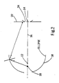
- FIG. 2 illustrates the effect of an adjustment of the discharge lamp 18 relative to the first focal point 12 in FIG. 1. It can be seen that the light beam emanating from the light source, the discharge lamp 18, is no longer collected by the reflector 10 in the second focal point 14 of the ellipsoid. Rather, a light spot occurs in the plane of the diaphragm 22 that is larger than the diaphragm opening 24. Part of the light energy of the light bundle is thus dimmed. The light spot becomes larger the further the discharge lamp 18 is moved to the left in FIG. There is thus an increasing darkening of the light beam emitted by the headlight.
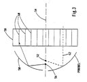
- FIG. 4 A further possibility of darkening the headlight is shown in FIG.
- the structure in FIG. 4 is similar to that in FIGS. 1 and 2, and corresponding parts in FIG. 4 are given the same reference numerals as there.
- the reflector 10 and the lamp 18 seated in the focal point 12 of the ellipsoid form a unit 28 which is movable along the optical axis 16 relative to the fixed diaphragm 22.
- the aperture 24 detects an increasingly smaller part of the light beam. This is shown in dashed lines in FIG. 4.
- conventional imaging optics which are not shown here in detail, can also be provided, which images the aperture 24 as a light spot on a scene on a stage.
- a slide can also be arranged at the location of the aperture.
Landscapes
- Engineering & Computer Science (AREA)
- General Engineering & Computer Science (AREA)
- Non-Portable Lighting Devices Or Systems Thereof (AREA)
Applications Claiming Priority (2)
| Application Number | Priority Date | Filing Date | Title |
|---|---|---|---|
| DE3919643 | 1989-06-16 | ||
| DE3919643A DE3919643A1 (de) | 1989-06-16 | 1989-06-16 | Scheinwerfer, der in seiner helligkeit stufenlos regelbar ist |
Publications (3)
| Publication Number | Publication Date |
|---|---|
| EP0402845A2 true EP0402845A2 (fr) | 1990-12-19 |
| EP0402845A3 EP0402845A3 (fr) | 1992-01-15 |
| EP0402845B1 EP0402845B1 (fr) | 1995-05-24 |
Family
ID=6382840
Family Applications (1)
| Application Number | Title | Priority Date | Filing Date |
|---|---|---|---|
| EP90111058A Expired - Lifetime EP0402845B1 (fr) | 1989-06-16 | 1990-06-12 | Projecteur à intensité lumineuse réglable de façon continue |
Country Status (3)
| Country | Link |
|---|---|
| EP (1) | EP0402845B1 (fr) |
| DE (2) | DE3919643A1 (fr) |
| ES (1) | ES2076258T3 (fr) |
Cited By (4)
| Publication number | Priority date | Publication date | Assignee | Title |
|---|---|---|---|---|
| WO2003001111A1 (fr) * | 2001-06-21 | 2003-01-03 | Carl Zeiss | Boitier de lampe |
| EP1482240A2 (fr) * | 2003-05-30 | 2004-12-01 | De Sisti Lighting S.p.A. | Dispositif de reglage de l'intensité lumineuse pour projecteurs avec lampe a decharge |
| EP1241399A3 (fr) * | 2001-03-16 | 2005-04-13 | Schott AG | Système optique pour projecteur avec une lentille à échelons |
| WO2012041692A3 (fr) * | 2010-09-30 | 2012-10-04 | Automotive Lighting Reutlingen Gmbh | Dispositif de commande et de réglage d'une lampe à décharge de gaz d'un phare de véhicule automobile |
Families Citing this family (10)
| Publication number | Priority date | Publication date | Assignee | Title |
|---|---|---|---|---|
| DE4003923A1 (de) * | 1990-02-09 | 1991-08-14 | Andreas Laurenz | Licht-streukoerper |
| DE10241899B4 (de) * | 2002-09-06 | 2006-06-29 | Adb-Ttv Technologies N.V./S.A. | Beleuchtungsvorrichtung |
| DE10241900A1 (de) * | 2002-09-06 | 2004-03-25 | Siemens Ag | Beleuchtungsvorrichtung |
| DE10361116B4 (de) | 2003-12-22 | 2010-06-17 | Auer Lighting Gmbh | Stufenlinsenscheinwerfer |
| US7483220B2 (en) * | 2003-12-22 | 2009-01-27 | Auer Lighting Gmbh | Optical arrangement with stepped lens |
| RU2302585C2 (ru) * | 2003-12-22 | 2007-07-10 | Шотт Аг | Прожектор с линзой френеля с взаимосвязанным изменением расстояния между осветительными элементами |
| DE102004013962A1 (de) * | 2003-12-22 | 2005-07-21 | Schott Ag | Stufenlinsenscheinwerfer mit gekoppelter Abstandsveränderung lichttechnischer Elemente |
| DE10361118B4 (de) * | 2003-12-22 | 2011-12-22 | Auer Lighting Gmbh | Stufenlinsenscheinwerfer |
| ES2277706B1 (es) * | 2004-09-24 | 2008-05-16 | Eduard Vila Vallejo | Dispositivo proyector ambiental portatil. |
| DE102005044237B4 (de) * | 2005-09-16 | 2012-05-03 | Auer Lighting Gmbh | Modularer Scheinwerfer |
Citations (5)
| Publication number | Priority date | Publication date | Assignee | Title |
|---|---|---|---|---|
| US3624386A (en) * | 1969-01-21 | 1971-11-30 | Strong Electric Corp The | Arc lamp |
| US3930149A (en) * | 1974-05-28 | 1975-12-30 | Sterndent Corp | Variable intensity dental light |
| GB2037415A (en) * | 1978-12-15 | 1980-07-09 | Furse & Co Ltd W | Spotlight |
| US4519020A (en) * | 1983-11-14 | 1985-05-21 | Little William D | Variable magnification stage light |
| EP0192882A2 (fr) * | 1985-02-28 | 1986-09-03 | VARI-LITE, INC.(a Delaware corporation) | Source lumineuse avec variation automatique de la couleur, de la saturation et de la divergence du faisceau |
Family Cites Families (5)
| Publication number | Priority date | Publication date | Assignee | Title |
|---|---|---|---|---|
| US1455929A (en) * | 1920-07-17 | 1923-05-22 | Neff Edward Dunbar | Spotlight-projecting device |
| FI41638C (fi) * | 1963-05-08 | 1970-01-12 | Mole Richardson England Ltd | Televisio- ja filmistudiovalaisin |
| AU2434471A (en) * | 1970-06-03 | 1972-07-20 | Berkey Technical Gu. K. ) Limited | Improvements in or relating to spot lamps |
| US4338654A (en) * | 1980-09-20 | 1982-07-06 | Richard Logothetis | Variable spot stage light |
| DE3719384A1 (de) * | 1987-06-05 | 1988-12-22 | Semperlux Gmbh | Leuchtensystem aus frei einstell- und steuerbaren lichtquellen |
-
1989
- 1989-06-16 DE DE3919643A patent/DE3919643A1/de not_active Ceased
-
1990
- 1990-06-12 DE DE59009112T patent/DE59009112D1/de not_active Expired - Fee Related
- 1990-06-12 ES ES90111058T patent/ES2076258T3/es not_active Expired - Lifetime
- 1990-06-12 EP EP90111058A patent/EP0402845B1/fr not_active Expired - Lifetime
Patent Citations (5)
| Publication number | Priority date | Publication date | Assignee | Title |
|---|---|---|---|---|
| US3624386A (en) * | 1969-01-21 | 1971-11-30 | Strong Electric Corp The | Arc lamp |
| US3930149A (en) * | 1974-05-28 | 1975-12-30 | Sterndent Corp | Variable intensity dental light |
| GB2037415A (en) * | 1978-12-15 | 1980-07-09 | Furse & Co Ltd W | Spotlight |
| US4519020A (en) * | 1983-11-14 | 1985-05-21 | Little William D | Variable magnification stage light |
| EP0192882A2 (fr) * | 1985-02-28 | 1986-09-03 | VARI-LITE, INC.(a Delaware corporation) | Source lumineuse avec variation automatique de la couleur, de la saturation et de la divergence du faisceau |
Cited By (7)
| Publication number | Priority date | Publication date | Assignee | Title |
|---|---|---|---|---|
| EP1241399A3 (fr) * | 2001-03-16 | 2005-04-13 | Schott AG | Système optique pour projecteur avec une lentille à échelons |
| WO2003001111A1 (fr) * | 2001-06-21 | 2003-01-03 | Carl Zeiss | Boitier de lampe |
| EP1482240A2 (fr) * | 2003-05-30 | 2004-12-01 | De Sisti Lighting S.p.A. | Dispositif de reglage de l'intensité lumineuse pour projecteurs avec lampe a decharge |
| EP1482240A3 (fr) * | 2003-05-30 | 2006-08-16 | De Sisti Lighting S.p.A. | Dispositif de reglage de l'intensité lumineuse pour projecteurs avec lampe a decharge |
| US7322706B2 (en) | 2003-05-30 | 2008-01-29 | De Sisti Lighting S.P.A. | Device for adjusting light intensity for discharge lamp projectors |
| WO2012041692A3 (fr) * | 2010-09-30 | 2012-10-04 | Automotive Lighting Reutlingen Gmbh | Dispositif de commande et de réglage d'une lampe à décharge de gaz d'un phare de véhicule automobile |
| CN103141161A (zh) * | 2010-09-30 | 2013-06-05 | 汽车照明罗伊特林根有限公司 | 用于机动车前照灯的气体放电灯的控制和调节装置 |
Also Published As
| Publication number | Publication date |
|---|---|
| DE59009112D1 (de) | 1995-06-29 |
| EP0402845A3 (fr) | 1992-01-15 |
| EP0402845B1 (fr) | 1995-05-24 |
| DE3919643A1 (de) | 1991-01-03 |
| ES2076258T3 (es) | 1995-11-01 |
Similar Documents
| Publication | Publication Date | Title |
|---|---|---|
| EP0402845B1 (fr) | Projecteur à intensité lumineuse réglable de façon continue | |
| EP2136126B1 (fr) | Lampe chirurgicale | |
| EP1241399B1 (fr) | Système optique pour projecteur avec une lentille à échelons | |
| EP1548358A1 (fr) | Projecteur avec lentille à échelons et distance variable entre la source et le réflecteur | |
| EP3953640B1 (fr) | Module lumineux pour un phare de véhicule automobile | |
| WO2020094376A1 (fr) | Projecteur de véhicule à micro-del comme source de lumière | |
| DE10361118B4 (de) | Stufenlinsenscheinwerfer | |
| DE3412476A1 (de) | Taschenleuchte | |
| EP1548357B1 (fr) | Projecteur avec une lentille à échelons | |
| DE2518539B2 (de) | Verfolgungsscheinwerfer für Bühnenbeleuchtung | |
| DE102010031678B4 (de) | Schnelle, variable Einfallswinkelbeleuchtung für Maschinensichtinspektionssystem | |
| WO1985004704A1 (fr) | Phare d'eclairage avec reglage de la repartition de l'intensite lumineuse | |
| DE3744060C2 (fr) | ||
| DE19908480A1 (de) | Scheinwerferanordnung für Fahrzeuge | |
| DE102008003215A1 (de) | Beleuchtungskörper zur Erzeugung gerichteten Lichts für die Qualitätskontrolle von Oberflächen | |
| DE3723129C2 (de) | Beleuchtungssystem für einen Schreibprojektor | |
| DE102017130209A1 (de) | Bewegliche Beleuchtungsvorrichtung | |
| US3152766A (en) | Lighting device | |
| DE2150341C3 (de) | Scheinwerfer mit scharfer Begrenzung seines Lichtbündels (Konturenscheinwerfer) | |
| DE19643220C1 (de) | Abbildungssystem mit veränderbarer Brennweite für einen Scheinwerfer der Bühnen-/Studiotechnik | |
| DE19722191A1 (de) | Lichtmodulationsvorrichtung | |
| DE102020133588A1 (de) | Scheinwerfer | |
| EP0828111A1 (fr) | Système de formation d'image à focale variable pour un projecteur de plateau | |
| EP1001210A1 (fr) | Système de projection d'images, à longeur focale modifiable pour les techniques d'éclairage sur scène ou en studio | |
| DE2150341B2 (de) | Scheinwerfer mit scharfer begrenzung seines lichtbuendels (konturenscheinwerfer) |
Legal Events
| Date | Code | Title | Description |
|---|---|---|---|
| PUAI | Public reference made under article 153(3) epc to a published international application that has entered the european phase |
Free format text: ORIGINAL CODE: 0009012 |
|
| AK | Designated contracting states |
Kind code of ref document: A2 Designated state(s): DE ES FR GB IT |
|
| PUAL | Search report despatched |
Free format text: ORIGINAL CODE: 0009013 |
|
| AK | Designated contracting states |
Kind code of ref document: A3 Designated state(s): DE ES FR GB IT |
|
| 17P | Request for examination filed |
Effective date: 19920708 |
|
| 17Q | First examination report despatched |
Effective date: 19940124 |
|
| GRAA | (expected) grant |
Free format text: ORIGINAL CODE: 0009210 |
|
| AK | Designated contracting states |
Kind code of ref document: B1 Designated state(s): DE ES FR GB IT |
|
| GBT | Gb: translation of ep patent filed (gb section 77(6)(a)/1977) |
Effective date: 19950522 |
|
| REF | Corresponds to: |
Ref document number: 59009112 Country of ref document: DE Date of ref document: 19950629 |
|
| ITF | It: translation for a ep patent filed |
Owner name: STUDIO JAUMANN |
|
| ET | Fr: translation filed | ||
| REG | Reference to a national code |
Ref country code: ES Ref legal event code: FG2A Ref document number: 2076258 Country of ref document: ES Kind code of ref document: T3 |
|
| PLBE | No opposition filed within time limit |
Free format text: ORIGINAL CODE: 0009261 |
|
| STAA | Information on the status of an ep patent application or granted ep patent |
Free format text: STATUS: NO OPPOSITION FILED WITHIN TIME LIMIT |
|
| 26N | No opposition filed | ||
| PGFP | Annual fee paid to national office [announced via postgrant information from national office to epo] |
Ref country code: GB Payment date: 19970612 Year of fee payment: 8 |
|
| PGFP | Annual fee paid to national office [announced via postgrant information from national office to epo] |
Ref country code: FR Payment date: 19970613 Year of fee payment: 8 |
|
| PGFP | Annual fee paid to national office [announced via postgrant information from national office to epo] |
Ref country code: ES Payment date: 19970616 Year of fee payment: 8 |
|
| PG25 | Lapsed in a contracting state [announced via postgrant information from national office to epo] |
Ref country code: GB Free format text: LAPSE BECAUSE OF NON-PAYMENT OF DUE FEES Effective date: 19980612 |
|
| PG25 | Lapsed in a contracting state [announced via postgrant information from national office to epo] |
Ref country code: ES Free format text: LAPSE BECAUSE OF NON-PAYMENT OF DUE FEES Effective date: 19980613 |
|
| GBPC | Gb: european patent ceased through non-payment of renewal fee |
Effective date: 19980612 |
|
| PG25 | Lapsed in a contracting state [announced via postgrant information from national office to epo] |
Ref country code: FR Free format text: LAPSE BECAUSE OF NON-PAYMENT OF DUE FEES Effective date: 19990226 |
|
| REG | Reference to a national code |
Ref country code: FR Ref legal event code: ST |
|
| REG | Reference to a national code |
Ref country code: ES Ref legal event code: FD2A Effective date: 20000503 |
|
| PG25 | Lapsed in a contracting state [announced via postgrant information from national office to epo] |
Ref country code: IT Free format text: LAPSE BECAUSE OF NON-PAYMENT OF DUE FEES;WARNING: LAPSES OF ITALIAN PATENTS WITH EFFECTIVE DATE BEFORE 2007 MAY HAVE OCCURRED AT ANY TIME BEFORE 2007. THE CORRECT EFFECTIVE DATE MAY BE DIFFERENT FROM THE ONE RECORDED. Effective date: 20050612 |
|
| PGFP | Annual fee paid to national office [announced via postgrant information from national office to epo] |
Ref country code: DE Payment date: 20070827 Year of fee payment: 18 |
|
| PG25 | Lapsed in a contracting state [announced via postgrant information from national office to epo] |
Ref country code: DE Free format text: LAPSE BECAUSE OF NON-PAYMENT OF DUE FEES Effective date: 20090101 |