EP1548357B1 - Projecteur avec une lentille à échelons - Google Patents
Projecteur avec une lentille à échelons Download PDFInfo
- Publication number
- EP1548357B1 EP1548357B1 EP04012006A EP04012006A EP1548357B1 EP 1548357 B1 EP1548357 B1 EP 1548357B1 EP 04012006 A EP04012006 A EP 04012006A EP 04012006 A EP04012006 A EP 04012006A EP 1548357 B1 EP1548357 B1 EP 1548357B1
- Authority
- EP
- European Patent Office
- Prior art keywords
- stepped lens
- reflector
- light
- stepped
- lens
- Prior art date
- Legal status (The legal status is an assumption and is not a legal conclusion. Google has not performed a legal analysis and makes no representation as to the accuracy of the status listed.)
- Expired - Lifetime
Links
- 238000005286 illumination Methods 0.000 claims description 8
- 239000011248 coating agent Substances 0.000 claims description 4
- 238000000576 coating method Methods 0.000 claims description 4
- 239000003989 dielectric material Substances 0.000 claims description 4
- 239000011521 glass Substances 0.000 claims description 4
- 229910052736 halogen Inorganic materials 0.000 claims description 3
- 150000002367 halogens Chemical class 0.000 claims description 3
- 229910052751 metal Inorganic materials 0.000 claims description 3
- 239000002184 metal Substances 0.000 claims description 3
- 229910052782 aluminium Inorganic materials 0.000 claims description 2
- XAGFODPZIPBFFR-UHFFFAOYSA-N aluminium Chemical compound [Al] XAGFODPZIPBFFR-UHFFFAOYSA-N 0.000 claims description 2
- 239000003814 drug Substances 0.000 claims description 2
- 238000001228 spectrum Methods 0.000 claims description 2
- 239000004411 aluminium Substances 0.000 claims 1
- -1 architecture Substances 0.000 claims 1
- 229920002994 synthetic fiber Polymers 0.000 claims 1
- 230000000694 effects Effects 0.000 description 6
- 230000001419 dependent effect Effects 0.000 description 5
- 238000009826 distribution Methods 0.000 description 4
- 238000000149 argon plasma sintering Methods 0.000 description 3
- 238000010276 construction Methods 0.000 description 2
- 230000003247 decreasing effect Effects 0.000 description 2
- 230000003287 optical effect Effects 0.000 description 2
- 239000004033 plastic Substances 0.000 description 2
- 229920003023 plastic Polymers 0.000 description 2
- 230000005855 radiation Effects 0.000 description 2
- 238000003860 storage Methods 0.000 description 2
- 230000003044 adaptive effect Effects 0.000 description 1
- 230000007797 corrosion Effects 0.000 description 1
- 238000005260 corrosion Methods 0.000 description 1
- 238000006073 displacement reaction Methods 0.000 description 1
- 238000003384 imaging method Methods 0.000 description 1
- 238000004519 manufacturing process Methods 0.000 description 1
- 239000000463 material Substances 0.000 description 1
- 238000004904 shortening Methods 0.000 description 1
- 239000007787 solid Substances 0.000 description 1
- 230000003595 spectral effect Effects 0.000 description 1
- 238000003892 spreading Methods 0.000 description 1
Images
Classifications
-
- G—PHYSICS
- G02—OPTICS
- G02B—OPTICAL ELEMENTS, SYSTEMS OR APPARATUS
- G02B3/00—Simple or compound lenses
- G02B3/02—Simple or compound lenses with non-spherical faces
- G02B3/08—Simple or compound lenses with non-spherical faces with discontinuous faces, e.g. Fresnel lens
-
- F—MECHANICAL ENGINEERING; LIGHTING; HEATING; WEAPONS; BLASTING
- F21—LIGHTING
- F21L—LIGHTING DEVICES OR SYSTEMS THEREOF, BEING PORTABLE OR SPECIALLY ADAPTED FOR TRANSPORTATION
- F21L4/00—Electric lighting devices with self-contained electric batteries or cells
- F21L4/005—Electric lighting devices with self-contained electric batteries or cells the device being a pocket lamp
-
- F—MECHANICAL ENGINEERING; LIGHTING; HEATING; WEAPONS; BLASTING
- F21—LIGHTING
- F21V—FUNCTIONAL FEATURES OR DETAILS OF LIGHTING DEVICES OR SYSTEMS THEREOF; STRUCTURAL COMBINATIONS OF LIGHTING DEVICES WITH OTHER ARTICLES, NOT OTHERWISE PROVIDED FOR
- F21V14/00—Controlling the distribution of the light emitted by adjustment of elements
- F21V14/02—Controlling the distribution of the light emitted by adjustment of elements by movement of light sources
-
- F—MECHANICAL ENGINEERING; LIGHTING; HEATING; WEAPONS; BLASTING
- F21—LIGHTING
- F21V—FUNCTIONAL FEATURES OR DETAILS OF LIGHTING DEVICES OR SYSTEMS THEREOF; STRUCTURAL COMBINATIONS OF LIGHTING DEVICES WITH OTHER ARTICLES, NOT OTHERWISE PROVIDED FOR
- F21V14/00—Controlling the distribution of the light emitted by adjustment of elements
- F21V14/06—Controlling the distribution of the light emitted by adjustment of elements by movement of refractors
-
- F—MECHANICAL ENGINEERING; LIGHTING; HEATING; WEAPONS; BLASTING
- F21—LIGHTING
- F21V—FUNCTIONAL FEATURES OR DETAILS OF LIGHTING DEVICES OR SYSTEMS THEREOF; STRUCTURAL COMBINATIONS OF LIGHTING DEVICES WITH OTHER ARTICLES, NOT OTHERWISE PROVIDED FOR
- F21V5/00—Refractors for light sources
- F21V5/04—Refractors for light sources of lens shape
- F21V5/045—Refractors for light sources of lens shape the lens having discontinuous faces, e.g. Fresnel lenses
-
- F—MECHANICAL ENGINEERING; LIGHTING; HEATING; WEAPONS; BLASTING
- F21—LIGHTING
- F21V—FUNCTIONAL FEATURES OR DETAILS OF LIGHTING DEVICES OR SYSTEMS THEREOF; STRUCTURAL COMBINATIONS OF LIGHTING DEVICES WITH OTHER ARTICLES, NOT OTHERWISE PROVIDED FOR
- F21V7/00—Reflectors for light sources
- F21V7/0008—Reflectors for light sources providing for indirect lighting
-
- F—MECHANICAL ENGINEERING; LIGHTING; HEATING; WEAPONS; BLASTING
- F21—LIGHTING
- F21V—FUNCTIONAL FEATURES OR DETAILS OF LIGHTING DEVICES OR SYSTEMS THEREOF; STRUCTURAL COMBINATIONS OF LIGHTING DEVICES WITH OTHER ARTICLES, NOT OTHERWISE PROVIDED FOR
- F21V7/00—Reflectors for light sources
- F21V7/22—Reflectors for light sources characterised by materials, surface treatments or coatings, e.g. dichroic reflectors
- F21V7/24—Reflectors for light sources characterised by materials, surface treatments or coatings, e.g. dichroic reflectors characterised by the material
-
- F—MECHANICAL ENGINEERING; LIGHTING; HEATING; WEAPONS; BLASTING
- F21—LIGHTING
- F21V—FUNCTIONAL FEATURES OR DETAILS OF LIGHTING DEVICES OR SYSTEMS THEREOF; STRUCTURAL COMBINATIONS OF LIGHTING DEVICES WITH OTHER ARTICLES, NOT OTHERWISE PROVIDED FOR
- F21V7/00—Reflectors for light sources
- F21V7/22—Reflectors for light sources characterised by materials, surface treatments or coatings, e.g. dichroic reflectors
- F21V7/28—Reflectors for light sources characterised by materials, surface treatments or coatings, e.g. dichroic reflectors characterised by coatings
-
- F—MECHANICAL ENGINEERING; LIGHTING; HEATING; WEAPONS; BLASTING
- F21—LIGHTING
- F21W—INDEXING SCHEME ASSOCIATED WITH SUBCLASSES F21K, F21L, F21S and F21V, RELATING TO USES OR APPLICATIONS OF LIGHTING DEVICES OR SYSTEMS
- F21W2131/00—Use or application of lighting devices or systems not provided for in codes F21W2102/00-F21W2121/00
- F21W2131/20—Lighting for medical use
-
- F—MECHANICAL ENGINEERING; LIGHTING; HEATING; WEAPONS; BLASTING
- F21—LIGHTING
- F21W—INDEXING SCHEME ASSOCIATED WITH SUBCLASSES F21K, F21L, F21S and F21V, RELATING TO USES OR APPLICATIONS OF LIGHTING DEVICES OR SYSTEMS
- F21W2131/00—Use or application of lighting devices or systems not provided for in codes F21W2102/00-F21W2121/00
- F21W2131/40—Lighting for industrial, commercial, recreational or military use
- F21W2131/406—Lighting for industrial, commercial, recreational or military use for theatres, stages or film studios
-
- F—MECHANICAL ENGINEERING; LIGHTING; HEATING; WEAPONS; BLASTING
- F21—LIGHTING
- F21Y—INDEXING SCHEME ASSOCIATED WITH SUBCLASSES F21K, F21L, F21S and F21V, RELATING TO THE FORM OR THE KIND OF THE LIGHT SOURCES OR OF THE COLOUR OF THE LIGHT EMITTED
- F21Y2101/00—Point-like light sources
Definitions
- the invention relates to a Fresnel lens, with adjustable opening angle of the exiting light beam, with a reflector, a lamp and at least one Fresnel lens.
- the photometrically relevant parts in ordinary Fresnel lenses usually comprise a lamp, a Fresnel lens and a spherical auxiliary reflector.
- the lamp filament is substantially invariable in the spherical center of the spherical reflector.
- a part of the light emitted by the lamp is reflected back into this light and supports the light emission in the front half space.
- This forward light is focused by the Fresnel lens.
- the degree of light bundling depends on the distance between the Fresnel lens and the lamp. If the lamp filament is located in the focal point of the Fresnel lens, the narrowest light bundling results.
- a quasi-parallel beam path also called a spot
- the opening angle of the emerging light beam is steadily increased.
- a diverging beam path which is also called flood, is obtained.
- a disadvantage of such headlamps is the poor light output, especially in their spot position, since only a relatively small solid angle range the lamp is detected by the Fresnel lens.
- it has the disadvantage that the reflected light from the spherical reflector to a large extent, the lamp coil itself again hits, is absorbed there and additionally heats the lamp filament.
- A1 is a headlight with a reflector, a shutter and a Fresnel lens known. With the headlamp the illumination is changed by an adjustment of the light source. This causes a brightness change of the light. A distance regulation between vertex and reflector and between the diaphragm and the reflector serves to regulate the brightness.
- the headlamp further has a lens or a mirror, both of which are positioned at an angle of 45 °. Through the mirror, the light is deflected and through the lens, the light is scattered. By moving the lens different beam angle of the light beam are generated.
- the DE 101 13 385 C1 describes a Fresnel lens in which the Fresnel lens is a converging lens whose light source side focal point is in spot position approximately in the reflector distant focal point of the ellipsoidal reflector. In this way, the lamp is not unnecessarily heated by reflected light. Further, with a correspondingly complicated to be designed guide both the distance ratio between the lamp and reflector and the distance ratio between the reflector and the Fresnel lens in dependence on each other set. However, this requires additional mechanical facilities.
- an LCD lighting arrangement with a Fresnel lens is known.
- the step lens has a light scattering surface arranged in the center of the lens.
- a Fresnel lens headlamp is to be created, which provides a homogeneously illuminated light field at high efficiency. Furthermore, this Fresnel spotlight should also be simple and inexpensive to manufacture.
- the inventors have found that these high light losses can be avoided in a surprisingly simple way with a diffuser.
- the step lens has a circularly formed and arranged only in the center of the Fresnel lens.
- the inventors made use of this effect in order to use the invention to create an automatic or adaptive light mixing system which, in synchronism with the adjustment of the Fresnel lens spotlight, mixes only that scattered light component with the geometrically-optically imaged light which is required for this position.
- This light mixing ratio which can be adapted almost optimally to the respectively required light distributions, is hereinafter abbreviated only as a mixing ratio.
- the mixing ratio of the fully illuminated stage lens can be defined by the choice of the diameter of the lens in relation to the remaining surface of the Fresnel lens and can be defined by the scattering properties of the Fresnel lens the aperture angle of the scattered light.
- the scattering effect itself can vary on the integrated diffusing screen, so that, for example, scattering areas of greater scattering and less strongly scattering areas are arranged in the middle of the scattering disk. As a result, a more focused beam is additionally widened and then extremely wide illumination angles can be realized.
- the edge of the lens may be designed not only abruptly ending but it may be designed to be steadily decreasing in its scattering effect and still extend below or above the Fresnel lens. This allows further adjustments to the position-dependent mixing ratios.
- the diffuser can be arranged in the preferred embodiments both at the light entrance and on the light exit side. Furthermore, there is the advantageous possibility to arrange lenses at the light entrance and at the light exit side. In this latter embodiment, also different scattering, for example, locally different scattering, lenses can be used.
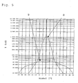
- the uniformity of the illuminance in the entire light field is obtained, as shown by way of example in FIG. 5 both for the spot and for a flood position.
- an ellipsoidal reflector with a large aperture is provided.
- the spot position is set by the fact that the lamp filament of a black body radiator, in particular a halogen lamp or the discharge arc of a discharge lamp is in the reflector-side focal point of the ellipsoid and the reflector distant second focus of the ellipsoid is arranged approximately in the real reflector near focal point of the Fresnel lens.
- the light reflected by the reflector is almost completely focused on the reflector distant focus of the ellipsoid before entering the Fresnel lens.
- the lamp filament located in the reflector-side focal point of the Fresnel lens or the discharge arc is imaged after passing through the Fresnel lens into the infinite and thus their light is converted into a nearly parallel beam.
- the light reflected from the reflector is almost completely detected by the Fresnel lens and emitted as a narrow spot light beam to the front.
- the ellipsoidal reflector is made of a metallic or transparent dielectric material.
- Prefers are used as dielectric materials glass and polymeric materials or plastics, which may be coated with metal, such as aluminum.
- one or both surfaces of the reflector are provided with a system of optically thin layers.
- the coating of the step lens advantageously comprises a dielectric interference layer system which changes the spectrum of the light passing through.
- both the reflector, the Fresnel lens and / or the lens may be coated at least on one side, for example, be coated in the case of plastic with an anti-scratch and / or anti-reflection coating.
- Another preferred embodiment of the invention comprises a metallic coating on one or both main surfaces of the reflector.
- the reflector may also be a metallic reflector which may be coated both uncoated and dielectrically or metallically to provide the desired spectral and corrosion properties.
- a preferred embodiment of the invention comprises a Fresnel lens in which the light-reflecting surface of the reflector, preferably having partial surfaces or facets, is light-scattering is structured and no, one or two surfaces of the Fresnel lens are light-scattering structured. This results in a fixed proportion of the superposition of scattered light to geometrically-optically imaged light, which can reduce dark rings in the light field.
- the step lens is preloaded on its surface, preferably thermally prestressed, so as to have a higher strength and thermal capacity.
- the use of the spotlight for architecture, medicine, film, stage, studio and photography and in a flashlight is provided.
- the diffuser can be arranged in the preferred embodiments both at the light entrance and on the light exit side. Furthermore, there is the advantageous possibility to arrange lenses at the light entrance and at the light exit side. In this latter embodiment, also different scattering, for example, locally different scattering, lenses can be used.
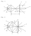
- the Fresnel lens headlamp substantially comprises an ellipsoidal reflector 1, a lamp 2, which may be an incandescent lamp, in particular a halogen lamp, a light-emitting diode, a light-emitting diode array or a gas discharge lamp, and a Fresnel lens 3, which is a collecting lens, preferably a plano-convex Fresnel lens.
- the reflektorferne focal point F2 of the ellipsoidal reflector 1 is superimposed approximately with the left-side real or positive focal point F3 of the Fresnel lens 3.
- the emerging from the headlight beam 4 is indicated in the figures only schematically by the outer edge beams.
- the distance a between the stepped lens 3 and the front edge of the reflector 1 is also shown in Fig. 1.
- the spot position is adjusted by arranging the lamp filament or the discharge arc of the lamp 2 essentially in the reflector-side focal point F1 of the reflector ellipsoid 1.
- the reflected light from the reflector 1 is almost completely directed in this position to the reflector distant focal point F2 of the ellipsoid.
- the left-side positive or real focal point F3 of the Fresnel lens 3 then coincides approximately with the focal point F2 of the reflector ellipsoid 1.
- a circular, centrally arranged lens 7 is provided, which generates a defined scattered light ratio and a defined opening angle of the scattered light. This results in a defined mixing ratio of the scattered light provided relative to the geometrically-optically imaged by the Fresnel lens 3.
- the scattering effect along the radius of the lens 7 changes in a continuous manner, so that in the center of the diffusing screen 7 more scattering areas and at their abruptly ending edge less scattering areas are arranged.
- the edge of the lens 7 is not only abruptly ending but it is this steadily decreasing in its scattering effect formed and this can also extend under or over the Fresnel lens.
- Fig. 5 shows an opening angle-dependent logarithmic representation of the luminous intensity of the Fresnel spotlight, is reproduced for the spot position with the line 8.
- Fig. 2 shows the embodiment of the illustrated in Fig. 1 Jardinnlinsenscheinwerfers in a first Flood ein, in which the reflektorferne focal point F2 of the reflector 1 is arranged approximately in a reflector-like surface of the Fresnel lens 3.
- the value of the displacement a with respect to the spot position is changed defined by a mechanical guidance.
- the construction basically corresponds to the construction of the Fresnel spotlight explained in FIG.
- FIG. 5 shows the light conditions with the line 9 by way of example for a flood position.
- the change in the distance a can be done manually in one embodiment, for which purpose an axial guidance of the optical components can be used.
- the optical components can also be moved by motor.
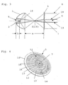
- FIG. 3 A further preferred embodiment is shown in FIG. 3.
- both the light which is shown only by way of example through the beam path 19 and would not contribute to the illumination without the auxiliary reflector, but also the part of the light that otherwise enters the step lens 3 directly can be used better for the desired light distribution.
- the shape of the auxiliary reflector 18 is advantageously selected so that this reflected light does not re-enter the lamp of the lamp 2, such as a filament or discharge zone, and this additionally heated unnecessarily.
- auxiliary reflector 18 may be applied to the inner and / or outer side of the glass body of the lamp 2.
- the glass of the lamp body can be shaped accordingly to achieve the desired directivity for the reflected light.
- Fig. 4 shows by way of example a step lens 3 with lens 7, as used by the invention.
- the step lens 3 has a transparent base body 10 and a Fresnel lens ring system 11 with annular lens sections 11, 12, 13, within which the circular lens 7 is arranged.
- the diffusing screen 7 is structured in a defined manner or has facets 15, 16, 17 with scattering behavior which can be exactly defined in a wide range, which is disclosed in the German patent application of the same applicant DE 103 43 630.8 with the title “spreading disc” are described.
- Fresnel spotlight according to the invention can be advantageously used to increase the light output in flashlights.
Landscapes
- Engineering & Computer Science (AREA)
- General Engineering & Computer Science (AREA)
- Physics & Mathematics (AREA)
- General Physics & Mathematics (AREA)
- Optics & Photonics (AREA)
- Non-Portable Lighting Devices Or Systems Thereof (AREA)
- Optical Elements Other Than Lenses (AREA)
Claims (17)
- Projecteur à lentille de Fresnel à différentes positions et, par conséquent, à angle d'ouverture réglable du faisceau lumineux émergent, comportant un réflecteur de préférence ellipsoïdal, une lampe et au moins une lentille de Fresnel, caractérisé en ce que la lentille de Fresnel présente un diffuseur de forme circulaire et disposé uniquement au centre de la lentille de Fresnel de telle manière que, dans chaque position du projecteur à lentille de Fresnel, des zones sombres puissent être évitées au milieu du champ d'éclairage.
- Projecteur à lentille de Fresnel selon la revendication 1, caractérisé en ce que la lentille de Fresnel définit avec le diffuseur un système de mélange de lumière qui modifie, en fonction de la position du projecteur à lentille de Fresnel, la fraction de lumière diffusée par rapport à la fraction de lumière formant une image de manière optique géométrique et, par conséquent, le rapport de mélange de lumière.
- Projecteur à lentille de Fresnel selon la revendication 1 ou 2, caractérisé en ce que la lentille de Fresnel présente un foyer réel qui est superposable à un foyer distant du réflecteur, notamment dans la position spot du projecteur à lentille de Fresnel.
- Projecteur à lentille de Fresnel selon l'une des revendications précédentes, caractérisé en ce que la lentille de Fresnel est une lentille convergente, de préférence de forme plan-convexe, réalisée en tant que lentille de Fresnel.
- Projecteur à lentille de Fresnel selon l'une des revendications précédentes, caractérisé en ce que la lentille de Fresnel comprend une lentille double présentant des propriétés de formation d'image corrigées de façon chromatique.
- Projecteur à lentille de Fresnel selon l'une des revendications précédentes, caractérisé en ce que le réflecteur consiste en une matière métallique ou transparente, de préférence diélectrique, en verre et/ou en matière plastique.
- Projecteur à lentille de Fresnel selon l'une des revendications précédentes, dans lequel au moins l'une des deux surfaces principales du réflecteur est pourvue d'un système de couches translucides.
- Projecteur à lentille de Fresnel selon l'une des revendications précédentes, dans lequel la surface de réflexion de lumière du réflecteur, de préférence présentant des surfaces partielles ou des facettes, est structurée de manière à diffuser la lumière, et aucune, une ou bien deux surface(s) de la lentille de Fresnel est ou sont structurée(s) pour diffuser la lumière, en plus du diffuseur.
- Projecteur à lentille de Fresnel selon l'une des revendications précédentes, caractérisé en ce que le réflecteur, la lentille de Fresnel et/ou le diffuseur sont revêtus d'une couche au moins sur une face.
- Projecteur à lentille de Fresnel selon la revendication 9, caractérisé en ce que le revêtement de la lentille de Fresnel comprend un système diélectrique de couches d'interférence, qui modifie le spectre de la lumière traversante.
- Projecteur à lentille de Fresnel selon l'une des revendications précédentes, caractérisé en ce qu'au moins l'une des deux surfaces principales du réflecteur est revêtue d'une couche de métal, de préférence de l'aluminium.
- Projecteur à lentille de Fresnel selon l'une des revendications précédentes, caractérisé en ce que la lampe est une lampe à incandescence, notamment une lampe à halogène, une diode luminescente, un groupe de diodes luminescentes, ou une lampe à décharge dans un gaz.
- Projecteur à lentille de Fresnel selon l'une des revendications précédentes, caractérisé en ce qu'il est prévu un réflecteur auxiliaire entre la lentille de Fresnel et le réflecteur.
- Projecteur à lentille de Fresnel selon l'une des revendications précédentes, caractérisé en ce que la lentille de Fresnel est soumise à une précontrainte au niveau de sa surface, de préférence une précontrainte par voie thermique.
- Ensemble d'éclairage comprenant un projecteur à lentille de Fresnel selon l'une des revendications précédentes 1 à 14, ainsi qu'un bloc associé d'alimentation électrique réseau, ou un ballast.
- Utilisation du projecteur à lentille de Fresnel selon l'une des revendications 1 à 14, ainsi que d'un ensemble d'éclairage selon la revendication 15 dans les domaines de la médecine, de l'architecture, du cinéma, de la scène, des studios et de la photographie.
- Lampe de poche comprenant un projecteur à lentille de Fresnel selon l'une des revendications précédentes 1 à 14.
Applications Claiming Priority (2)
| Application Number | Priority Date | Filing Date | Title |
|---|---|---|---|
| DE10361116 | 2003-12-22 | ||
| DE10361116A DE10361116B4 (de) | 2003-12-22 | 2003-12-22 | Stufenlinsenscheinwerfer |
Publications (3)
| Publication Number | Publication Date |
|---|---|
| EP1548357A1 EP1548357A1 (fr) | 2005-06-29 |
| EP1548357B1 true EP1548357B1 (fr) | 2008-01-23 |
| EP1548357B8 EP1548357B8 (fr) | 2008-03-26 |
Family
ID=34530388
Family Applications (1)
| Application Number | Title | Priority Date | Filing Date |
|---|---|---|---|
| EP04012006A Expired - Lifetime EP1548357B8 (fr) | 2003-12-22 | 2004-05-21 | Projecteur avec une lentille à échelons |
Country Status (7)
| Country | Link |
|---|---|
| US (1) | US20050135096A1 (fr) |
| EP (1) | EP1548357B8 (fr) |
| JP (1) | JP4199727B2 (fr) |
| CN (1) | CN1637342B (fr) |
| AT (1) | ATE384913T1 (fr) |
| DE (2) | DE10361116B4 (fr) |
| RU (1) | RU2293910C2 (fr) |
Families Citing this family (10)
| Publication number | Priority date | Publication date | Assignee | Title |
|---|---|---|---|---|
| US8262252B2 (en) | 2005-07-13 | 2012-09-11 | Koninklijke Philips Electronics N.V. | Illumination system |
| WO2010146893A1 (fr) * | 2009-06-15 | 2010-12-23 | シャープ株式会社 | Dispositif d'éclairage, dispositif d'affichage et récepteur de télévision |
| TWM373496U (en) * | 2009-07-29 | 2010-02-01 | Chunghwa Picture Tubes Ltd | Collimated system with multi-backlight source |
| RU2525166C2 (ru) * | 2010-03-16 | 2014-08-10 | Общество с ограниченной ответственностью "ДиС ПЛЮС" | Способ управления цветностью светового потока белого светодиода и устройство для осуществления способа |
| US20130120986A1 (en) * | 2011-11-12 | 2013-05-16 | Raydex Technology, Inc. | High efficiency directional light source with concentrated light output |
| US9303846B2 (en) * | 2013-05-31 | 2016-04-05 | GE Lighting Solutions, LLC | Directional lamp with adjustable beam spread |
| CN103697389A (zh) * | 2013-12-29 | 2014-04-02 | 哈尔滨固泰电子有限责任公司 | 可变色温的汽车灯具 |
| CN104121523A (zh) * | 2014-07-30 | 2014-10-29 | 深圳市九洲光电科技有限公司 | 一种复眼透镜调光调色led射灯 |
| CN104930583B (zh) * | 2015-06-30 | 2018-09-21 | 中国科学院自动化研究所 | 聚光型取暖器 |
| CN109780457B (zh) * | 2017-01-11 | 2020-05-19 | 哈尔滨理工大学 | 能够移动的环形透光遮挡板结构及新生儿鼻孔照明装置 |
Citations (1)
| Publication number | Priority date | Publication date | Assignee | Title |
|---|---|---|---|---|
| US20020024822A1 (en) * | 2000-08-31 | 2002-02-28 | Gregory Pond | Combined stop/turn/tail/clearance lamp using light emitting diode technology |
Family Cites Families (23)
| Publication number | Priority date | Publication date | Assignee | Title |
|---|---|---|---|---|
| US1992668A (en) * | 1933-06-21 | 1935-02-26 | Gen Motors Corp | Lens or cover glass for head lamps and the like |
| US2853599A (en) * | 1956-05-17 | 1958-09-23 | Kliegl Bros Universal Electric | Oval beam lens |
| US3576563A (en) * | 1968-05-20 | 1971-04-27 | Railroad Accessories Corp | Railroad signal having light piping from source mounted an exterior of reflector cone |
| US4383289A (en) * | 1980-12-15 | 1983-05-10 | Ian Lewin | Task lighting fixture for concentrating illumination |
| US4519020A (en) * | 1983-11-14 | 1985-05-21 | Little William D | Variable magnification stage light |
| DE3413310A1 (de) | 1984-04-09 | 1985-10-17 | Dr.-Ing. Willing GmbH, 8604 Scheßlitz | Beleuchtungsscheinwerfer mit verstellbarem ausstrahlungswinkel |
| DE3826988A1 (de) * | 1988-08-09 | 1990-02-15 | Kodak Ag | Fahrzeugscheinwerfer |
| DE3919643A1 (de) | 1989-06-16 | 1991-01-03 | Reiche & Vogel Gmbh | Scheinwerfer, der in seiner helligkeit stufenlos regelbar ist |
| DE3926618A1 (de) * | 1989-08-11 | 1991-02-14 | Philips Patentverwaltung | Reflektorleuchte |
| US5138540A (en) * | 1990-04-24 | 1992-08-11 | Koito Manufacturing Co., Ltd. | Variable light distribution type headlamp |
| DE9207494U1 (de) * | 1991-07-08 | 1992-11-26 | O.I.B. GmbH Optische-Interferenz-Bauelemente, O-6900 Jena | Optisches Bauteil |
| US5488493A (en) * | 1993-11-01 | 1996-01-30 | Hughes Aircraft Company | Holographic CHMSL including a hologram assembly and a refractive element laminarly attached thereto for diverging zero order beam |
| RU2087794C1 (ru) * | 1996-02-14 | 1997-08-20 | Молохина Лариса Аркадьевна | Противоослепляющее осветительное устройство |
| US6220736B1 (en) * | 1997-07-10 | 2001-04-24 | Robert Bosch Gmbh | Headlight for a vehicle |
| JP2000182410A (ja) * | 1998-12-17 | 2000-06-30 | Koito Mfg Co Ltd | 車両用灯具 |
| DE19901391A1 (de) * | 1999-01-15 | 2000-09-14 | Weigert Dedo Film Gmbh | Scheinwerfer mit veränderlichem Abstrahlwinkel und mit asphärischer Frontlinse |
| IT1318056B1 (it) * | 2000-06-27 | 2003-07-21 | Coemar Spa | Proiettore luminoso particolarmente per la proiezione di luce adimensioni variabili e ad infiniti colori. |
| DE10063134A1 (de) * | 2000-12-18 | 2002-06-27 | Weigert Dedo Film Gmbh | Fokussierbarer Scheinwerfer mit Negativlinse |
| DE10113385C1 (de) * | 2001-03-16 | 2002-08-29 | Schott Glas | Stufenlinsenscheinwerfer |
| ITMI20021625A1 (it) * | 2002-07-23 | 2004-01-23 | Coemar Spa | Proiettore luminoso con mezzi per delimitare perimetralmente il fascio di luce emessa |
| US6809869B2 (en) * | 2002-08-28 | 2004-10-26 | Genlyte Thomas Group Llc | Zoomable beamspreader for non-imaging illumination applications |
| JP3863126B2 (ja) * | 2003-06-26 | 2006-12-27 | 旭テクノグラス株式会社 | プロジェクター用ガラス製反射鏡およびその製造方法 |
| US20040263346A1 (en) * | 2003-06-27 | 2004-12-30 | Guide Corporation, A Delaware Corporation | Solid state adaptive forward lighting system |
-
2003
- 2003-12-22 DE DE10361116A patent/DE10361116B4/de not_active Expired - Fee Related
-
2004
- 2004-05-21 AT AT04012006T patent/ATE384913T1/de not_active IP Right Cessation
- 2004-05-21 EP EP04012006A patent/EP1548357B8/fr not_active Expired - Lifetime
- 2004-05-21 DE DE502004006033T patent/DE502004006033D1/de not_active Expired - Lifetime
- 2004-08-10 CN CN2004100564388A patent/CN1637342B/zh not_active Expired - Fee Related
- 2004-08-11 US US10/915,785 patent/US20050135096A1/en not_active Abandoned
- 2004-12-21 RU RU2004137464/28A patent/RU2293910C2/ru not_active IP Right Cessation
- 2004-12-22 JP JP2004371853A patent/JP4199727B2/ja not_active Expired - Fee Related
Patent Citations (1)
| Publication number | Priority date | Publication date | Assignee | Title |
|---|---|---|---|---|
| US20020024822A1 (en) * | 2000-08-31 | 2002-02-28 | Gregory Pond | Combined stop/turn/tail/clearance lamp using light emitting diode technology |
Also Published As
| Publication number | Publication date |
|---|---|
| DE502004006033D1 (de) | 2008-03-13 |
| JP4199727B2 (ja) | 2008-12-17 |
| JP2005183403A (ja) | 2005-07-07 |
| DE10361116B4 (de) | 2010-06-17 |
| RU2293910C2 (ru) | 2007-02-20 |
| ATE384913T1 (de) | 2008-02-15 |
| CN1637342B (zh) | 2010-04-28 |
| US20050135096A1 (en) | 2005-06-23 |
| EP1548357A1 (fr) | 2005-06-29 |
| DE10361116A1 (de) | 2005-07-21 |
| CN1637342A (zh) | 2005-07-13 |
| RU2004137464A (ru) | 2006-06-10 |
| EP1548357B8 (fr) | 2008-03-26 |
Similar Documents
| Publication | Publication Date | Title |
|---|---|---|
| EP1548358A1 (fr) | Projecteur avec lentille à échelons et distance variable entre la source et le réflecteur | |
| EP1548356A1 (fr) | Projecteur avec lentille à échelons et distance variable entre la source et le réflecteur | |
| EP1548355B1 (fr) | Phare avec lentille à échelons | |
| EP1241399B1 (fr) | Système optique pour projecteur avec une lentille à échelons | |
| EP1697686B1 (fr) | Phare avec lentille à échelons | |
| DE1936715C3 (de) | Optische Projektionsvorrichtung | |
| EP2467635B1 (fr) | Lampe à led, en particulier phare à led | |
| EP1548357B1 (fr) | Projecteur avec une lentille à échelons | |
| DE19901391A1 (de) | Scheinwerfer mit veränderlichem Abstrahlwinkel und mit asphärischer Frontlinse | |
| DE2135698A1 (de) | Optisches System insbesondere Projektor | |
| DE4312889A1 (de) | Vorwiegend direkt strahlende Leuchte mit einem abgehängten Lichtleitkörper | |
| DE10308602A1 (de) | Röntgenortungslichtsystem | |
| DE202005011293U1 (de) | Leuchte mit einem rohrförmigen Lichtleitelement | |
| EP0176527A1 (fr) | Phare d'eclairage avec reglage de la repartition de l'intensite lumineuse | |
| DE102004014045A1 (de) | Stufenlinsenscheinwerfer mit gekoppelter Abstandsveränderung lichttechnischer Elemente | |
| EP3353465B1 (fr) | Lampe de poche comprenant une source lumineuse | |
| DE3810297C2 (de) | Reflektorsystem mit Reflektoren verschiedener Krümmung mit einem kleinen Ausstrahlungswinkel in einer Leuchte zur Ausleuchtung eines Objektes | |
| DE102012018419A1 (de) | LED-Reflektor-System für Beleuchtungsaufgaben | |
| DE602004012652T2 (de) | Vorrichtung zur Einstellung der Lichtintensität für Projektoren mit Entladungslampe | |
| DE29922697U1 (de) | Schweinwerfer | |
| DE29804248U1 (de) | Scheinwerfer | |
| DE202015104987U1 (de) | Taschenlampe mit einer Lichtquelle | |
| DE29804251U1 (de) | Scheinwerfer | |
| DE102020133588A1 (de) | Scheinwerfer | |
| DE102008053488B4 (de) | Reflektorlampe |
Legal Events
| Date | Code | Title | Description |
|---|---|---|---|
| PUAI | Public reference made under article 153(3) epc to a published international application that has entered the european phase |
Free format text: ORIGINAL CODE: 0009012 |
|
| 17P | Request for examination filed |
Effective date: 20040621 |
|
| AK | Designated contracting states |
Kind code of ref document: A1 Designated state(s): AT BE BG CH CY CZ DE DK EE ES FI FR GB GR HU IE IT LI LU MC NL PL PT RO SE SI SK TR |
|
| AX | Request for extension of the european patent |
Extension state: AL HR LT LV MK |
|
| AKX | Designation fees paid | ||
| RBV | Designated contracting states (corrected) |
Designated state(s): AT BE BG CH CY CZ DE DK EE ES FI FR GB GR HU IE IT LI LU MC NL PL PT RO SE SI SK TR |
|
| GRAP | Despatch of communication of intention to grant a patent |
Free format text: ORIGINAL CODE: EPIDOSNIGR1 |
|
| GRAS | Grant fee paid |
Free format text: ORIGINAL CODE: EPIDOSNIGR3 |
|
| GRAA | (expected) grant |
Free format text: ORIGINAL CODE: 0009210 |
|
| AK | Designated contracting states |
Kind code of ref document: B1 Designated state(s): AT BE BG CH CY CZ DE DK EE ES FI FR GB GR HU IE IT LI LU MC NL PL PT RO SE SI SK TR |
|
| REG | Reference to a national code |
Ref country code: GB Ref legal event code: FG4D Free format text: NOT ENGLISH |
|
| REG | Reference to a national code |
Ref country code: CH Ref legal event code: EP |
|
| RAP2 | Party data changed (patent owner data changed or rights of a patent transferred) |
Owner name: AUER LIGHTING GMBH |
|
| REG | Reference to a national code |
Ref country code: IE Ref legal event code: FG4D Free format text: LANGUAGE OF EP DOCUMENT: GERMAN |
|
| REF | Corresponds to: |
Ref document number: 502004006033 Country of ref document: DE Date of ref document: 20080313 Kind code of ref document: P |
|
| NLT2 | Nl: modifications (of names), taken from the european patent patent bulletin |
Owner name: AUER LIGHTING GMBH Effective date: 20080227 |
|
| GBT | Gb: translation of ep patent filed (gb section 77(6)(a)/1977) |
Effective date: 20080413 |
|
| NLV1 | Nl: lapsed or annulled due to failure to fulfill the requirements of art. 29p and 29m of the patents act | ||
| PG25 | Lapsed in a contracting state [announced via postgrant information from national office to epo] |
Ref country code: FI Free format text: LAPSE BECAUSE OF FAILURE TO SUBMIT A TRANSLATION OF THE DESCRIPTION OR TO PAY THE FEE WITHIN THE PRESCRIBED TIME-LIMIT Effective date: 20080123 Ref country code: ES Free format text: LAPSE BECAUSE OF FAILURE TO SUBMIT A TRANSLATION OF THE DESCRIPTION OR TO PAY THE FEE WITHIN THE PRESCRIBED TIME-LIMIT Effective date: 20080504 |
|
| PG25 | Lapsed in a contracting state [announced via postgrant information from national office to epo] |
Ref country code: BG Free format text: LAPSE BECAUSE OF FAILURE TO SUBMIT A TRANSLATION OF THE DESCRIPTION OR TO PAY THE FEE WITHIN THE PRESCRIBED TIME-LIMIT Effective date: 20080423 |
|
| PG25 | Lapsed in a contracting state [announced via postgrant information from national office to epo] |
Ref country code: SI Free format text: LAPSE BECAUSE OF FAILURE TO SUBMIT A TRANSLATION OF THE DESCRIPTION OR TO PAY THE FEE WITHIN THE PRESCRIBED TIME-LIMIT Effective date: 20080123 Ref country code: PT Free format text: LAPSE BECAUSE OF FAILURE TO SUBMIT A TRANSLATION OF THE DESCRIPTION OR TO PAY THE FEE WITHIN THE PRESCRIBED TIME-LIMIT Effective date: 20080623 Ref country code: PL Free format text: LAPSE BECAUSE OF FAILURE TO SUBMIT A TRANSLATION OF THE DESCRIPTION OR TO PAY THE FEE WITHIN THE PRESCRIBED TIME-LIMIT Effective date: 20080123 |
|
| REG | Reference to a national code |
Ref country code: IE Ref legal event code: FD4D |
|
| ET | Fr: translation filed | ||
| PG25 | Lapsed in a contracting state [announced via postgrant information from national office to epo] |
Ref country code: CZ Free format text: LAPSE BECAUSE OF FAILURE TO SUBMIT A TRANSLATION OF THE DESCRIPTION OR TO PAY THE FEE WITHIN THE PRESCRIBED TIME-LIMIT Effective date: 20080123 Ref country code: SE Free format text: LAPSE BECAUSE OF FAILURE TO SUBMIT A TRANSLATION OF THE DESCRIPTION OR TO PAY THE FEE WITHIN THE PRESCRIBED TIME-LIMIT Effective date: 20080423 Ref country code: DK Free format text: LAPSE BECAUSE OF FAILURE TO SUBMIT A TRANSLATION OF THE DESCRIPTION OR TO PAY THE FEE WITHIN THE PRESCRIBED TIME-LIMIT Effective date: 20080123 Ref country code: IE Free format text: LAPSE BECAUSE OF FAILURE TO SUBMIT A TRANSLATION OF THE DESCRIPTION OR TO PAY THE FEE WITHIN THE PRESCRIBED TIME-LIMIT Effective date: 20080123 Ref country code: SK Free format text: LAPSE BECAUSE OF FAILURE TO SUBMIT A TRANSLATION OF THE DESCRIPTION OR TO PAY THE FEE WITHIN THE PRESCRIBED TIME-LIMIT Effective date: 20080123 Ref country code: NL Free format text: LAPSE BECAUSE OF FAILURE TO SUBMIT A TRANSLATION OF THE DESCRIPTION OR TO PAY THE FEE WITHIN THE PRESCRIBED TIME-LIMIT Effective date: 20080123 |
|
| PG25 | Lapsed in a contracting state [announced via postgrant information from national office to epo] |
Ref country code: RO Free format text: LAPSE BECAUSE OF FAILURE TO SUBMIT A TRANSLATION OF THE DESCRIPTION OR TO PAY THE FEE WITHIN THE PRESCRIBED TIME-LIMIT Effective date: 20080123 |
|
| PLBE | No opposition filed within time limit |
Free format text: ORIGINAL CODE: 0009261 |
|
| STAA | Information on the status of an ep patent application or granted ep patent |
Free format text: STATUS: NO OPPOSITION FILED WITHIN TIME LIMIT |
|
| BERE | Be: lapsed |
Owner name: SCHOTT A.G. Effective date: 20080531 |
|
| 26N | No opposition filed |
Effective date: 20081024 |
|
| PG25 | Lapsed in a contracting state [announced via postgrant information from national office to epo] |
Ref country code: MC Free format text: LAPSE BECAUSE OF NON-PAYMENT OF DUE FEES Effective date: 20080531 |
|
| REG | Reference to a national code |
Ref country code: CH Ref legal event code: PL |
|
| PG25 | Lapsed in a contracting state [announced via postgrant information from national office to epo] |
Ref country code: CH Free format text: LAPSE BECAUSE OF NON-PAYMENT OF DUE FEES Effective date: 20080531 Ref country code: LI Free format text: LAPSE BECAUSE OF NON-PAYMENT OF DUE FEES Effective date: 20080531 |
|
| PG25 | Lapsed in a contracting state [announced via postgrant information from national office to epo] |
Ref country code: BE Free format text: LAPSE BECAUSE OF NON-PAYMENT OF DUE FEES Effective date: 20080531 |
|
| PG25 | Lapsed in a contracting state [announced via postgrant information from national office to epo] |
Ref country code: EE Free format text: LAPSE BECAUSE OF FAILURE TO SUBMIT A TRANSLATION OF THE DESCRIPTION OR TO PAY THE FEE WITHIN THE PRESCRIBED TIME-LIMIT Effective date: 20080123 |
|
| PG25 | Lapsed in a contracting state [announced via postgrant information from national office to epo] |
Ref country code: CY Free format text: LAPSE BECAUSE OF FAILURE TO SUBMIT A TRANSLATION OF THE DESCRIPTION OR TO PAY THE FEE WITHIN THE PRESCRIBED TIME-LIMIT Effective date: 20080123 |
|
| PG25 | Lapsed in a contracting state [announced via postgrant information from national office to epo] |
Ref country code: AT Free format text: LAPSE BECAUSE OF NON-PAYMENT OF DUE FEES Effective date: 20080521 Ref country code: IT Free format text: LAPSE BECAUSE OF FAILURE TO SUBMIT A TRANSLATION OF THE DESCRIPTION OR TO PAY THE FEE WITHIN THE PRESCRIBED TIME-LIMIT Effective date: 20080123 |
|
| PG25 | Lapsed in a contracting state [announced via postgrant information from national office to epo] |
Ref country code: LU Free format text: LAPSE BECAUSE OF NON-PAYMENT OF DUE FEES Effective date: 20080521 Ref country code: HU Free format text: LAPSE BECAUSE OF FAILURE TO SUBMIT A TRANSLATION OF THE DESCRIPTION OR TO PAY THE FEE WITHIN THE PRESCRIBED TIME-LIMIT Effective date: 20080724 |
|
| PG25 | Lapsed in a contracting state [announced via postgrant information from national office to epo] |
Ref country code: TR Free format text: LAPSE BECAUSE OF FAILURE TO SUBMIT A TRANSLATION OF THE DESCRIPTION OR TO PAY THE FEE WITHIN THE PRESCRIBED TIME-LIMIT Effective date: 20080123 |
|
| PG25 | Lapsed in a contracting state [announced via postgrant information from national office to epo] |
Ref country code: GR Free format text: LAPSE BECAUSE OF FAILURE TO SUBMIT A TRANSLATION OF THE DESCRIPTION OR TO PAY THE FEE WITHIN THE PRESCRIBED TIME-LIMIT Effective date: 20080424 |
|
| REG | Reference to a national code |
Ref country code: FR Ref legal event code: PLFP Year of fee payment: 13 |
|
| REG | Reference to a national code |
Ref country code: FR Ref legal event code: PLFP Year of fee payment: 14 |
|
| PGFP | Annual fee paid to national office [announced via postgrant information from national office to epo] |
Ref country code: FR Payment date: 20170523 Year of fee payment: 14 Ref country code: DE Payment date: 20170523 Year of fee payment: 14 Ref country code: GB Payment date: 20170519 Year of fee payment: 14 |
|
| REG | Reference to a national code |
Ref country code: DE Ref legal event code: R119 Ref document number: 502004006033 Country of ref document: DE |
|
| GBPC | Gb: european patent ceased through non-payment of renewal fee |
Effective date: 20180521 |
|
| PG25 | Lapsed in a contracting state [announced via postgrant information from national office to epo] |
Ref country code: GB Free format text: LAPSE BECAUSE OF NON-PAYMENT OF DUE FEES Effective date: 20180521 Ref country code: DE Free format text: LAPSE BECAUSE OF NON-PAYMENT OF DUE FEES Effective date: 20181201 Ref country code: FR Free format text: LAPSE BECAUSE OF NON-PAYMENT OF DUE FEES Effective date: 20180531 |