EP1548357B1 - Stepped lens projector - Google Patents
Stepped lens projector Download PDFInfo
- Publication number
- EP1548357B1 EP1548357B1 EP04012006A EP04012006A EP1548357B1 EP 1548357 B1 EP1548357 B1 EP 1548357B1 EP 04012006 A EP04012006 A EP 04012006A EP 04012006 A EP04012006 A EP 04012006A EP 1548357 B1 EP1548357 B1 EP 1548357B1
- Authority
- EP
- European Patent Office
- Prior art keywords
- stepped lens
- reflector
- light
- stepped
- lens
- Prior art date
- Legal status (The legal status is an assumption and is not a legal conclusion. Google has not performed a legal analysis and makes no representation as to the accuracy of the status listed.)
- Not-in-force
Links
Images
Classifications
-
- G—PHYSICS
- G02—OPTICS
- G02B—OPTICAL ELEMENTS, SYSTEMS OR APPARATUS
- G02B3/00—Simple or compound lenses
- G02B3/02—Simple or compound lenses with non-spherical faces
- G02B3/08—Simple or compound lenses with non-spherical faces with discontinuous faces, e.g. Fresnel lens
-
- F—MECHANICAL ENGINEERING; LIGHTING; HEATING; WEAPONS; BLASTING
- F21—LIGHTING
- F21L—LIGHTING DEVICES OR SYSTEMS THEREOF, BEING PORTABLE OR SPECIALLY ADAPTED FOR TRANSPORTATION
- F21L4/00—Electric lighting devices with self-contained electric batteries or cells
- F21L4/005—Electric lighting devices with self-contained electric batteries or cells the device being a pocket lamp
-
- F—MECHANICAL ENGINEERING; LIGHTING; HEATING; WEAPONS; BLASTING
- F21—LIGHTING
- F21V—FUNCTIONAL FEATURES OR DETAILS OF LIGHTING DEVICES OR SYSTEMS THEREOF; STRUCTURAL COMBINATIONS OF LIGHTING DEVICES WITH OTHER ARTICLES, NOT OTHERWISE PROVIDED FOR
- F21V14/00—Controlling the distribution of the light emitted by adjustment of elements
- F21V14/02—Controlling the distribution of the light emitted by adjustment of elements by movement of light sources
-
- F—MECHANICAL ENGINEERING; LIGHTING; HEATING; WEAPONS; BLASTING
- F21—LIGHTING
- F21V—FUNCTIONAL FEATURES OR DETAILS OF LIGHTING DEVICES OR SYSTEMS THEREOF; STRUCTURAL COMBINATIONS OF LIGHTING DEVICES WITH OTHER ARTICLES, NOT OTHERWISE PROVIDED FOR
- F21V14/00—Controlling the distribution of the light emitted by adjustment of elements
- F21V14/06—Controlling the distribution of the light emitted by adjustment of elements by movement of refractors
-
- F—MECHANICAL ENGINEERING; LIGHTING; HEATING; WEAPONS; BLASTING
- F21—LIGHTING
- F21V—FUNCTIONAL FEATURES OR DETAILS OF LIGHTING DEVICES OR SYSTEMS THEREOF; STRUCTURAL COMBINATIONS OF LIGHTING DEVICES WITH OTHER ARTICLES, NOT OTHERWISE PROVIDED FOR
- F21V5/00—Refractors for light sources
- F21V5/04—Refractors for light sources of lens shape
- F21V5/045—Refractors for light sources of lens shape the lens having discontinuous faces, e.g. Fresnel lenses
-
- F—MECHANICAL ENGINEERING; LIGHTING; HEATING; WEAPONS; BLASTING
- F21—LIGHTING
- F21V—FUNCTIONAL FEATURES OR DETAILS OF LIGHTING DEVICES OR SYSTEMS THEREOF; STRUCTURAL COMBINATIONS OF LIGHTING DEVICES WITH OTHER ARTICLES, NOT OTHERWISE PROVIDED FOR
- F21V7/00—Reflectors for light sources
- F21V7/0008—Reflectors for light sources providing for indirect lighting
-
- F—MECHANICAL ENGINEERING; LIGHTING; HEATING; WEAPONS; BLASTING
- F21—LIGHTING
- F21V—FUNCTIONAL FEATURES OR DETAILS OF LIGHTING DEVICES OR SYSTEMS THEREOF; STRUCTURAL COMBINATIONS OF LIGHTING DEVICES WITH OTHER ARTICLES, NOT OTHERWISE PROVIDED FOR
- F21V7/00—Reflectors for light sources
- F21V7/22—Reflectors for light sources characterised by materials, surface treatments or coatings, e.g. dichroic reflectors
- F21V7/24—Reflectors for light sources characterised by materials, surface treatments or coatings, e.g. dichroic reflectors characterised by the material
-
- F—MECHANICAL ENGINEERING; LIGHTING; HEATING; WEAPONS; BLASTING
- F21—LIGHTING
- F21V—FUNCTIONAL FEATURES OR DETAILS OF LIGHTING DEVICES OR SYSTEMS THEREOF; STRUCTURAL COMBINATIONS OF LIGHTING DEVICES WITH OTHER ARTICLES, NOT OTHERWISE PROVIDED FOR
- F21V7/00—Reflectors for light sources
- F21V7/22—Reflectors for light sources characterised by materials, surface treatments or coatings, e.g. dichroic reflectors
- F21V7/28—Reflectors for light sources characterised by materials, surface treatments or coatings, e.g. dichroic reflectors characterised by coatings
-
- F—MECHANICAL ENGINEERING; LIGHTING; HEATING; WEAPONS; BLASTING
- F21—LIGHTING
- F21W—INDEXING SCHEME ASSOCIATED WITH SUBCLASSES F21K, F21L, F21S and F21V, RELATING TO USES OR APPLICATIONS OF LIGHTING DEVICES OR SYSTEMS
- F21W2131/00—Use or application of lighting devices or systems not provided for in codes F21W2102/00-F21W2121/00
- F21W2131/20—Lighting for medical use
-
- F—MECHANICAL ENGINEERING; LIGHTING; HEATING; WEAPONS; BLASTING
- F21—LIGHTING
- F21W—INDEXING SCHEME ASSOCIATED WITH SUBCLASSES F21K, F21L, F21S and F21V, RELATING TO USES OR APPLICATIONS OF LIGHTING DEVICES OR SYSTEMS
- F21W2131/00—Use or application of lighting devices or systems not provided for in codes F21W2102/00-F21W2121/00
- F21W2131/40—Lighting for industrial, commercial, recreational or military use
- F21W2131/406—Lighting for industrial, commercial, recreational or military use for theatres, stages or film studios
-
- F—MECHANICAL ENGINEERING; LIGHTING; HEATING; WEAPONS; BLASTING
- F21—LIGHTING
- F21Y—INDEXING SCHEME ASSOCIATED WITH SUBCLASSES F21K, F21L, F21S and F21V, RELATING TO THE FORM OR THE KIND OF THE LIGHT SOURCES OR OF THE COLOUR OF THE LIGHT EMITTED
- F21Y2101/00—Point-like light sources
Definitions
- the invention relates to a Fresnel lens, with adjustable opening angle of the exiting light beam, with a reflector, a lamp and at least one Fresnel lens.
- the photometrically relevant parts in ordinary Fresnel lenses usually comprise a lamp, a Fresnel lens and a spherical auxiliary reflector.
- the lamp filament is substantially invariable in the spherical center of the spherical reflector.
- a part of the light emitted by the lamp is reflected back into this light and supports the light emission in the front half space.
- This forward light is focused by the Fresnel lens.
- the degree of light bundling depends on the distance between the Fresnel lens and the lamp. If the lamp filament is located in the focal point of the Fresnel lens, the narrowest light bundling results.
- a quasi-parallel beam path also called a spot
- the opening angle of the emerging light beam is steadily increased.
- a diverging beam path which is also called flood, is obtained.
- a disadvantage of such headlamps is the poor light output, especially in their spot position, since only a relatively small solid angle range the lamp is detected by the Fresnel lens.
- it has the disadvantage that the reflected light from the spherical reflector to a large extent, the lamp coil itself again hits, is absorbed there and additionally heats the lamp filament.
- A1 is a headlight with a reflector, a shutter and a Fresnel lens known. With the headlamp the illumination is changed by an adjustment of the light source. This causes a brightness change of the light. A distance regulation between vertex and reflector and between the diaphragm and the reflector serves to regulate the brightness.
- the headlamp further has a lens or a mirror, both of which are positioned at an angle of 45 °. Through the mirror, the light is deflected and through the lens, the light is scattered. By moving the lens different beam angle of the light beam are generated.
- the DE 101 13 385 C1 describes a Fresnel lens in which the Fresnel lens is a converging lens whose light source side focal point is in spot position approximately in the reflector distant focal point of the ellipsoidal reflector. In this way, the lamp is not unnecessarily heated by reflected light. Further, with a correspondingly complicated to be designed guide both the distance ratio between the lamp and reflector and the distance ratio between the reflector and the Fresnel lens in dependence on each other set. However, this requires additional mechanical facilities.
- an LCD lighting arrangement with a Fresnel lens is known.
- the step lens has a light scattering surface arranged in the center of the lens.
- a Fresnel lens headlamp is to be created, which provides a homogeneously illuminated light field at high efficiency. Furthermore, this Fresnel spotlight should also be simple and inexpensive to manufacture.
- the inventors have found that these high light losses can be avoided in a surprisingly simple way with a diffuser.
- the step lens has a circularly formed and arranged only in the center of the Fresnel lens.
- the inventors made use of this effect in order to use the invention to create an automatic or adaptive light mixing system which, in synchronism with the adjustment of the Fresnel lens spotlight, mixes only that scattered light component with the geometrically-optically imaged light which is required for this position.
- This light mixing ratio which can be adapted almost optimally to the respectively required light distributions, is hereinafter abbreviated only as a mixing ratio.
- the mixing ratio of the fully illuminated stage lens can be defined by the choice of the diameter of the lens in relation to the remaining surface of the Fresnel lens and can be defined by the scattering properties of the Fresnel lens the aperture angle of the scattered light.
- the scattering effect itself can vary on the integrated diffusing screen, so that, for example, scattering areas of greater scattering and less strongly scattering areas are arranged in the middle of the scattering disk. As a result, a more focused beam is additionally widened and then extremely wide illumination angles can be realized.
- the edge of the lens may be designed not only abruptly ending but it may be designed to be steadily decreasing in its scattering effect and still extend below or above the Fresnel lens. This allows further adjustments to the position-dependent mixing ratios.
- the diffuser can be arranged in the preferred embodiments both at the light entrance and on the light exit side. Furthermore, there is the advantageous possibility to arrange lenses at the light entrance and at the light exit side. In this latter embodiment, also different scattering, for example, locally different scattering, lenses can be used.
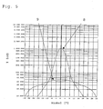
- the uniformity of the illuminance in the entire light field is obtained, as shown by way of example in FIG. 5 both for the spot and for a flood position.
- an ellipsoidal reflector with a large aperture is provided.
- the spot position is set by the fact that the lamp filament of a black body radiator, in particular a halogen lamp or the discharge arc of a discharge lamp is in the reflector-side focal point of the ellipsoid and the reflector distant second focus of the ellipsoid is arranged approximately in the real reflector near focal point of the Fresnel lens.
- the light reflected by the reflector is almost completely focused on the reflector distant focus of the ellipsoid before entering the Fresnel lens.
- the lamp filament located in the reflector-side focal point of the Fresnel lens or the discharge arc is imaged after passing through the Fresnel lens into the infinite and thus their light is converted into a nearly parallel beam.
- the light reflected from the reflector is almost completely detected by the Fresnel lens and emitted as a narrow spot light beam to the front.
- the ellipsoidal reflector is made of a metallic or transparent dielectric material.
- Prefers are used as dielectric materials glass and polymeric materials or plastics, which may be coated with metal, such as aluminum.
- one or both surfaces of the reflector are provided with a system of optically thin layers.
- the coating of the step lens advantageously comprises a dielectric interference layer system which changes the spectrum of the light passing through.
- both the reflector, the Fresnel lens and / or the lens may be coated at least on one side, for example, be coated in the case of plastic with an anti-scratch and / or anti-reflection coating.
- Another preferred embodiment of the invention comprises a metallic coating on one or both main surfaces of the reflector.
- the reflector may also be a metallic reflector which may be coated both uncoated and dielectrically or metallically to provide the desired spectral and corrosion properties.
- a preferred embodiment of the invention comprises a Fresnel lens in which the light-reflecting surface of the reflector, preferably having partial surfaces or facets, is light-scattering is structured and no, one or two surfaces of the Fresnel lens are light-scattering structured. This results in a fixed proportion of the superposition of scattered light to geometrically-optically imaged light, which can reduce dark rings in the light field.
- the step lens is preloaded on its surface, preferably thermally prestressed, so as to have a higher strength and thermal capacity.
- the use of the spotlight for architecture, medicine, film, stage, studio and photography and in a flashlight is provided.
- the diffuser can be arranged in the preferred embodiments both at the light entrance and on the light exit side. Furthermore, there is the advantageous possibility to arrange lenses at the light entrance and at the light exit side. In this latter embodiment, also different scattering, for example, locally different scattering, lenses can be used.
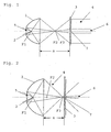
- the Fresnel lens headlamp substantially comprises an ellipsoidal reflector 1, a lamp 2, which may be an incandescent lamp, in particular a halogen lamp, a light-emitting diode, a light-emitting diode array or a gas discharge lamp, and a Fresnel lens 3, which is a collecting lens, preferably a plano-convex Fresnel lens.
- the reflektorferne focal point F2 of the ellipsoidal reflector 1 is superimposed approximately with the left-side real or positive focal point F3 of the Fresnel lens 3.
- the emerging from the headlight beam 4 is indicated in the figures only schematically by the outer edge beams.
- the distance a between the stepped lens 3 and the front edge of the reflector 1 is also shown in Fig. 1.
- the spot position is adjusted by arranging the lamp filament or the discharge arc of the lamp 2 essentially in the reflector-side focal point F1 of the reflector ellipsoid 1.
- the reflected light from the reflector 1 is almost completely directed in this position to the reflector distant focal point F2 of the ellipsoid.
- the left-side positive or real focal point F3 of the Fresnel lens 3 then coincides approximately with the focal point F2 of the reflector ellipsoid 1.
- a circular, centrally arranged lens 7 is provided, which generates a defined scattered light ratio and a defined opening angle of the scattered light. This results in a defined mixing ratio of the scattered light provided relative to the geometrically-optically imaged by the Fresnel lens 3.
- the scattering effect along the radius of the lens 7 changes in a continuous manner, so that in the center of the diffusing screen 7 more scattering areas and at their abruptly ending edge less scattering areas are arranged.
- the edge of the lens 7 is not only abruptly ending but it is this steadily decreasing in its scattering effect formed and this can also extend under or over the Fresnel lens.
- Fig. 5 shows an opening angle-dependent logarithmic representation of the luminous intensity of the Fresnel spotlight, is reproduced for the spot position with the line 8.
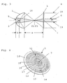
- Fig. 2 shows the embodiment of the illustrated in Fig. 1 Jardinnlinsenscheinwerfers in a first Flood ein, in which the reflektorferne focal point F2 of the reflector 1 is arranged approximately in a reflector-like surface of the Fresnel lens 3.
- the value of the displacement a with respect to the spot position is changed defined by a mechanical guidance.
- the construction basically corresponds to the construction of the Fresnel spotlight explained in FIG.
- FIG. 5 shows the light conditions with the line 9 by way of example for a flood position.
- the change in the distance a can be done manually in one embodiment, for which purpose an axial guidance of the optical components can be used.
- the optical components can also be moved by motor.
- FIG. 3 A further preferred embodiment is shown in FIG. 3.
- both the light which is shown only by way of example through the beam path 19 and would not contribute to the illumination without the auxiliary reflector, but also the part of the light that otherwise enters the step lens 3 directly can be used better for the desired light distribution.
- the shape of the auxiliary reflector 18 is advantageously selected so that this reflected light does not re-enter the lamp of the lamp 2, such as a filament or discharge zone, and this additionally heated unnecessarily.
- auxiliary reflector 18 may be applied to the inner and / or outer side of the glass body of the lamp 2.
- the glass of the lamp body can be shaped accordingly to achieve the desired directivity for the reflected light.
- Fig. 4 shows by way of example a step lens 3 with lens 7, as used by the invention.
- the step lens 3 has a transparent base body 10 and a Fresnel lens ring system 11 with annular lens sections 11, 12, 13, within which the circular lens 7 is arranged.
- the diffusing screen 7 is structured in a defined manner or has facets 15, 16, 17 with scattering behavior which can be exactly defined in a wide range, which is disclosed in the German patent application of the same applicant DE 103 43 630.8 with the title “spreading disc” are described.
- Fresnel spotlight according to the invention can be advantageously used to increase the light output in flashlights.
Abstract
Description
Die Erfindung betrifft einen Stufenlinsenscheinwerfer, mit einstellbarem Öffnungswinkel des austretenden Lichtbündels, mit einem Reflektor, einer Lampe und mindestens einer Stufenlinse.The invention relates to a Fresnel lens, with adjustable opening angle of the exiting light beam, with a reflector, a lamp and at least one Fresnel lens.
Die lichttechnisch relevanten Teile bei gewöhnlichen Stufenlinsenscheinwerfern umfassen in der Regel eine Lampe, eine Stufenlinse (Fresnellinse) und einen sphärischen Hilfsreflektor. Herkömmlich befindet sich die Lampenwendel im Wesentlichen unveränderlich im Kugelmittelpunkt des sphärischen Reflektors. Dadurch wird ein Teil des von der Lampe abgestrahlten Lichts in diese zurückreflektiert und die Lichtabstrahlung in den vorderen Halbraum unterstützt. Dieses nach vorn gerichtete Licht wird durch die Stufenlinse gebündelt. Der Grad der Lichtbündelung ist jedoch von dem Abstand zwischen der Stufenlinse und der Lampe abhängig. Befindet sich die Lampenwendel im Brennpunkt der Stufenlinse, so ergibt sich die engste Lichtbündelung. Dadurch wird ein quasiparalleler Strahlengang, auch Spot genannt, erhalten. Durch Verkürzung des Abstandes zwischen der Stufenlinse und der Lampe wird der Öffnungswinkel des austretenden Lichtbündels stetig vergrössert. Dadurch wird ein divergierender Strahlengang, welcher auch Flood genannt wird, erhalten.The photometrically relevant parts in ordinary Fresnel lenses usually comprise a lamp, a Fresnel lens and a spherical auxiliary reflector. Conventionally, the lamp filament is substantially invariable in the spherical center of the spherical reflector. As a result, a part of the light emitted by the lamp is reflected back into this light and supports the light emission in the front half space. This forward light is focused by the Fresnel lens. However, the degree of light bundling depends on the distance between the Fresnel lens and the lamp. If the lamp filament is located in the focal point of the Fresnel lens, the narrowest light bundling results. As a result, a quasi-parallel beam path, also called a spot, is obtained. By shortening the distance between the Fresnel lens and the lamp, the opening angle of the emerging light beam is steadily increased. As a result, a diverging beam path, which is also called flood, is obtained.
Nachteilig an derartigen Scheinwerfern ist jedoch die schlechte Lichtausbeute insbesondere in deren Spotstellung, da hier nur ein verhältnismässig kleiner Raumwinkelbereich der Lampe durch die Stufenlinse erfasst wird. Ausserdem wirkt es sich nachteilig aus, dass das von dem sphärischen Reflektor reflektierte Licht zu einem grossen Teil die Lampenwendel selbst wieder trifft, dort absorbiert wird und die Lampenwendel zusätzlich aufheizt.A disadvantage of such headlamps, however, is the poor light output, especially in their spot position, since only a relatively small solid angle range the lamp is detected by the Fresnel lens. In addition, it has the disadvantage that the reflected light from the spherical reflector to a large extent, the lamp coil itself again hits, is absorbed there and additionally heats the lamp filament.
Aus der
Aus der
Die
Mit zunehmender Verkleinerung der Lichtquelle, etwa bei Hochleistungs-Hochdruck-Entladungslampen kann jedoch im ausgeleuchteten Lichtfeld ein immer stärker ausgeprägter mittlerer dunkler Bereich auftreten, welcher mit streuenden Einrichtungen innerhalb des Reflektors nicht oder nur noch mit grossen Lichtverlusten kompensiert werden kann. Auch die herkömmlichen, zur Vermeidung einer Abbildung des Emissionszentrums der Lichtquelle verwendeten streuenden Einrichtungen schaffen hier nur bedingt, wenn überhaupt Abhilfe, da auch hierbei in jeder Stellung des Stufenlinsenscheinwerfers mindestens der dunkle mittige Öffnungskegel homogen ausgeleuchtet werden muss. Gerade hierdurch kommt es jedoch besonders in der Spotstellung zu grossen Lichtverlusten, da hier nur ein dunkler Bereich mit sehr kleinem Öffnungswinkel vorliegt aber bei den herkömmlichen Stufenlinsen mit streuenden Einrichtungen dennoch die volle Fläche der Stufenlinse zur Streuung des Lichtfelds verwendet wird.With increasing reduction of the light source, such as in high-performance high-pressure discharge lamps, however, an increasingly pronounced middle dark area can occur in the illuminated light field, which can not be compensated with scattering devices within the reflector or only with large light losses. Also, the conventional scattering devices used to avoid imaging the emission center of the light source provide only limited, if any, remedy since here too in every position of the Fresnel spotlight at least the dark central aperture cone must be homogeneously illuminated. However, this leads to large light losses, especially in the spot position, since there is only a dark area with a very small opening angle, but in the case of the conventional stepped lenses with scattering devices, the full area of the step lens is used to scatter the light field.
Aus
Mit der Erfindung soll ein Stufenlinsenscheinwerfer geschaffen werden, der bei hohem Wirkungsgrad ein homogen ausgeleuchtetes Lichtfeld bereitstellt. Ferner soll dieser Stufenlinsenscheinwerfer auch einfach und kostengünstig herzustellen sein.With the invention, a Fresnel lens headlamp is to be created, which provides a homogeneously illuminated light field at high efficiency. Furthermore, this Fresnel spotlight should also be simple and inexpensive to manufacture.
Diese Aufgabe wird auf überraschend einfache Weise mit einem Stufenlinsenscheinwerfer gemäss Anspruch 1 sowie einem Beleuchtungsset gemäss Anspruch 17 gelöst.This object is achieved in a surprisingly simple manner with a Fresnel lens according to
Die Erfinder haben herausgefunden, dass diese hohen Lichtverluste auf überraschend einfache Weise mit einer Streuscheibe vermieden werden können.The inventors have found that these high light losses can be avoided in a surprisingly simple way with a diffuser.
Nach der Erfindung weist die Stufenlinse eine kreisförmig ausgebildete und nur noch im Zentrum der Stufenlinse angeordnete Streuscheibe auf.According to the invention, the step lens has a circularly formed and arranged only in the center of the Fresnel lens.
Folglich können in jeder Stellung des Stufenlinsenscheinwerfers die dunklen Bereiche in der Mitte des Beleuchtungsfelds sehr wirksam vermieden werden, aber es kommt nicht mehr zu den hohen Lichtverlusten in der Spotstellung des Reflektors.Consequently, in any position of the Fresnel lens spotlight, the dark areas in the center of the illumination field can be avoided very effectively, but it no longer comes to the high light losses in the spot position of the reflector.
In überraschender Weise zeigt es sich, dass der geometrisch-optische Strahlengang des aus dem Reflektor austretenden Lichts am Ort der Stufenlinse genau dann einen kleineren Bereich ausleuchtet, wenn der benötigte Anteil an gestreutem Licht erhöht ist.Surprisingly, it turns out that the geometrical-optical beam path of the light emerging from the reflector at the location of the stepped lens illuminates a smaller area if and only if the required proportion of scattered light is increased.
Diese Wirkung haben sich die Erfinder zu nutze gemacht, um mit der Erfindung ein automatisches oder adaptives Lichtmischsystem zu schaffen, welches synchron zu der Verstellung des Stufenlinsenscheinwerfers nur denjenigen Streulichtanteil zum geometrisch-optisch abgebildeten Licht hinzu mischt, welcher für diese Stellung benötigt wird.The inventors made use of this effect in order to use the invention to create an automatic or adaptive light mixing system which, in synchronism with the adjustment of the Fresnel lens spotlight, mixes only that scattered light component with the geometrically-optically imaged light which is required for this position.
Dieses Lichtmischverhältnis, welches nahezu optimal an die jeweils erforderlichen Lichtverteilungen adaptiert werden kann, wird nachfolgend abgekürzt nur noch als Mischverhältnis bezeichnet.This light mixing ratio, which can be adapted almost optimally to the respectively required light distributions, is hereinafter abbreviated only as a mixing ratio.
Durch dieses automatische Lichtmischsystem wird im Wesentlichen für jede Stellung des Reflektors das richtige Mischverhältnis und somit stets ein sehr homogen ausgeleuchtetes Lichtfeld geschaffen ohne dass hierbei jedoch unnötige Streuverluste auftreten.By means of this automatic light mixing system, the correct mixing ratio and thus always a very homogeneously illuminated light field is essentially created for each position of the reflector without, however, causing unnecessary scattering losses.
Hierbei kann durch die Wahl des Durchmessers der Streuscheibe im Verhältnis zur verbleibenden Fläche der Stufenlinse das Mischverhältnis der vollflächig ausgeleuchteten Stufenlinse definiert werden und kann durch die Streueigenschaften der Stufenlinse der Öffnungswinkel des gestreuten Lichts definiert werden.In this case, the mixing ratio of the fully illuminated stage lens can be defined by the choice of the diameter of the lens in relation to the remaining surface of the Fresnel lens and can be defined by the scattering properties of the Fresnel lens the aperture angle of the scattered light.
Ferner kann auf der integrierten Streuscheibe selbst die streuende Wirkung variieren, so dass beispielsweise in der Mitte der Streuscheibe stärker streuende Bereiche und an deren Rand weniger stark streuende Bereiche angeordnet sind. Hierdurch wird ein stärker fokussiertes Strahlenbündel zusätzlich noch aufgeweitet und es lassen sich dann extrem breite Ausleuchtungswinkel realisieren.Furthermore, the scattering effect itself can vary on the integrated diffusing screen, so that, for example, scattering areas of greater scattering and less strongly scattering areas are arranged in the middle of the scattering disk. As a result, a more focused beam is additionally widened and then extremely wide illumination angles can be realized.
Alternativ kann auch der Rand der Streuscheibe nicht nur abrupt endend ausgestaltet sein sondern es kann dieser in dessen streuender Wirkung stetig abnehmend gestaltet sein und sich noch unter oder über der Stufenlinse erstrecken. Hierdurch lassen sich weitere Anpassungen an die stellungsabhängigen Mischverhältnisse vornehmen.Alternatively, the edge of the lens may be designed not only abruptly ending but it may be designed to be steadily decreasing in its scattering effect and still extend below or above the Fresnel lens. This allows further adjustments to the position-dependent mixing ratios.
Die Streuscheibe kann bei den bevorzugten Ausführungsformen sowohl an der Lichteintritts- als auch an der Lichtaustrittseite angeordnet sein. Ferner besteht die vorteilhafte Möglichkeit, Streuscheiben an der Lichteintritts und an der Lichtaustrittsseite anzuordnen. Bei dieser letztgenannten Ausführungsform können auch verschieden streuende, beispielsweise örtlich verschieden streuende, Streuscheiben verwendet werden.The diffuser can be arranged in the preferred embodiments both at the light entrance and on the light exit side. Furthermore, there is the advantageous possibility to arrange lenses at the light entrance and at the light exit side. In this latter embodiment, also different scattering, for example, locally different scattering, lenses can be used.
Gleichzeitig wird die Gleichmässigkeit der Beleuchtungsstärke im gesamten Lichtfeld erhalten, wie dieses beispielhaft in Figur 5 sowohl für die Spot- als auch für eine Floodstellung dargestellt ist.At the same time, the uniformity of the illuminance in the entire light field is obtained, as shown by way of example in FIG. 5 both for the spot and for a flood position.
Erfindungsgemäss ist ein ellipsoider Reflektor mit grosser Apertur vorgesehen. Die Spotstellung wird dadurch eingestellt, dass sich die Lampenwendel eines Schwarzkörperstrahlers, insbesondere einer Halogenlampe oder der Entladungsbogen einer Entladungslampe im reflektorseitigen Brennpunkt des Ellipsoids befindet und der reflektorferne zweite Brennpunkt des Ellipsoids in etwa im reellen reflektornahen Brennpunkt der Stufenlinse angeordnet ist.According to the invention, an ellipsoidal reflector with a large aperture is provided. The spot position is set by the fact that the lamp filament of a black body radiator, in particular a halogen lamp or the discharge arc of a discharge lamp is in the reflector-side focal point of the ellipsoid and the reflector distant second focus of the ellipsoid is arranged approximately in the real reflector near focal point of the Fresnel lens.
Das von dem Reflektor reflektierte Licht wird vor Eintritt in die Stufenlinse nahezu vollständig auf den reflektorfernen Brennpunkt des Ellipsoids fokussiert. Die sich im reflektorseitigen Brennpunkt der Stufenlinse befindliche Lampenwendel oder der Entladungsbogen wird nach dem Hindurchtreten durch die Stufenlinse in das Unendliche abgebildet und wird somit deren Licht in ein nahezu paralleles Strahlenbündel überführt.The light reflected by the reflector is almost completely focused on the reflector distant focus of the ellipsoid before entering the Fresnel lens. The lamp filament located in the reflector-side focal point of the Fresnel lens or the discharge arc is imaged after passing through the Fresnel lens into the infinite and thus their light is converted into a nearly parallel beam.
Bei zweckmässiger Wahl des Aperturwinkels von Reflektor und Stufenlinse wird das von dem Reflektor reflektierte Licht nahezu vollständig von der Stufenlinse erfasst und als enges Spot-Lichtbündel nach vorne abgestrahlt.With appropriate choice of the aperture angle of reflector and Fresnel lens, the light reflected from the reflector is almost completely detected by the Fresnel lens and emitted as a narrow spot light beam to the front.
Eine Ausführungsform der Erfindung besteht darin, dass der Ellipsoidreflektor aus einem metallischen oder transparenten dielektrischen Material besteht. Bevorzugt werden als dielektrische Materialien Glas und polymere Materialien bzw. Kunststoffe verwendet, welche mit Metall, beispielsweise Aluminium, beschichtet sein können.An embodiment of the invention is that the ellipsoidal reflector is made of a metallic or transparent dielectric material. Prefers are used as dielectric materials glass and polymeric materials or plastics, which may be coated with metal, such as aluminum.
Alternativ oder zusätzlich wird zur Herstellung einer reflektierenden Oberfläche bei einer Ausführungsform mit transparentem dielektrischem Material eine der beiden oder beide Oberflächen des Reflektors mit einem System optisch dünner Schichten versehen. Vorteilhaft umfasst die Beschichtung der Stufenlinse ein dielektrisches Interferenz-Schichtsystem, welches das Spektrum des hindurchtretenden Lichtes verändert. Hierdurch können vorteilhafterweise sichtbare Strahlungsanteile reflektiert und die unsichtbaren Anteile, insbesondere Wärmestrahlungsanteile, durchgelassen werden.Alternatively or additionally, to produce a reflective surface in one embodiment with transparent dielectric material, one or both surfaces of the reflector are provided with a system of optically thin layers. The coating of the step lens advantageously comprises a dielectric interference layer system which changes the spectrum of the light passing through. As a result, visible radiation components can advantageously be reflected and the invisible components, in particular heat radiation components, transmitted.
Generell können sowohl der Reflektor, die Stufenlinse und/oder die Streuscheibe zumindest einseitig beschichtet sein, beispielsweise im Falle von Kunststoff mit einer Antikratz und/oder Antireflexschicht beschichtet sein.In general, both the reflector, the Fresnel lens and / or the lens may be coated at least on one side, for example, be coated in the case of plastic with an anti-scratch and / or anti-reflection coating.
Eine weitere bevorzugte Ausführungsform der Erfindung umfasst eine metallische Beschichtung auf einer oder beiden Hauptoberflächen des Reflektors.Another preferred embodiment of the invention comprises a metallic coating on one or both main surfaces of the reflector.
In weiterer alternativer Ausgestaltung kann der Reflektor auch ein metallischer Reflektor welcher sowohl unbeschichtet als auch dielektrisch oder metallisch beschichtet sein kann, um die erwünschten spektralen und Korrosionseigenschaften bereitzustellen.In a further alternative embodiment, the reflector may also be a metallic reflector which may be coated both uncoated and dielectrically or metallically to provide the desired spectral and corrosion properties.
Eine bevorzugte Ausführungsform der Erfindung umfasst einen Stufenlinsenscheinwerfer, bei welchem die lichtreflektierende Oberfläche des Reflektors, vorzugsweise Teilflächen oder Facetten aufweisend, lichtstreuend strukturiert ist und keine, eine oder zwei Oberflächen der Stufenlinse lichtstreuend strukturiert sind. Hierdurch kommt es zu einem festgelegten Anteil der Überlagerung gestreuten Lichts zu geometrisch-optisch abgebildetem Licht, welcher dunkle Ringe im Lichtfeld mindern kann.A preferred embodiment of the invention comprises a Fresnel lens in which the light-reflecting surface of the reflector, preferably having partial surfaces or facets, is light-scattering is structured and no, one or two surfaces of the Fresnel lens are light-scattering structured. This results in a fixed proportion of the superposition of scattered light to geometrically-optically imaged light, which can reduce dark rings in the light field.
In vorteilhafter Weise ist die Stufenlinse an deren Oberfläche vorgespannt, vorzugsweise thermisch vorgespannt, um derart eine höhere Festigkeit und thermische Belastbarkeit aufzuweisen.Advantageously, the step lens is preloaded on its surface, preferably thermally prestressed, so as to have a higher strength and thermal capacity.
Erfindungsgemäss ist die Verwendung des Scheinwerfers für Architektur, Medizin, Film, Bühne, Studio und Fotografie sowie in einer Taschenlampe vorgesehen.According to the invention, the use of the spotlight for architecture, medicine, film, stage, studio and photography and in a flashlight is provided.
Die Streuscheibe kann bei den bevorzugten Ausführungsformen sowohl an der Lichteintritts- als auch an der Lichtaustrittseite angeordnet sein. Ferner besteht die vorteilhafte Möglichkeit, Streuscheiben an der Lichteintritts und an der Lichtaustrittsseite anzuordnen. Bei dieser letztgenannten Ausführungsform können auch verschieden streuende, beispielsweise örtlich verschieden streuende, Streuscheiben verwendet werden.The diffuser can be arranged in the preferred embodiments both at the light entrance and on the light exit side. Furthermore, there is the advantageous possibility to arrange lenses at the light entrance and at the light exit side. In this latter embodiment, also different scattering, for example, locally different scattering, lenses can be used.
Die Erfindung wird anhand bevorzugter Ausführungsformen und unter Bezugnahme auf die beigefügten Zeichnungen detaillierter beschrieben.The invention will be described in more detail by means of preferred embodiments and with reference to the accompanying drawings.
Es zeigen:
- Fig. 1
- eine Ausführungsform des Stufenlinsen-scheinwerfers in Spotstellung, wobei der reflektorferne Brennpunkt des Reflektors in etwa mit dem linksseitigen, reellen Brennpunkt der Stufenlinse überlagert ist,
- Fig. 2
- die in Fig. 1 gezeigte Ausführungsform des Stufenlinsenscheinwerfers in einer ersten Floodstellung, wobei der reflektorferne Brennpunkt des Reflektors nahe einer Oberfläche der Stufenlinse angeordnet ist,
- Fig. 3
- die in Fig. 1 dargestellte Ausführungsform des Stufenlinsenscheinwerfers in Spotstellung mit einem zusätzlichen Hilfsreflektor, mittels welchem ein weiterer Teil des Lichts zunächst in den Reflektor und von diesem in die Stufenlinse gelenkt wird,
- Fig. 4
- eine sammelnde Stufenlinse mit zentral angeordneter Streuscheibe,
- Fig. 5
- eine öffnungswinkelabhängige logarithmische Darstellung der Lichtstärke des Stufenlinsen-scheinwerfers in dessen Spot- und in einer von dessen Floodstellungen.
- Fig. 1
- an embodiment of the Fresnel spotlight in the spot position, wherein the reflector of the reflector distant from the reflector is superimposed approximately to the left-side, real focal point of the Fresnel lens,
- Fig. 2
- 1, the embodiment of the Fresnel lens in a first Floodstellung, wherein the reflector of the reflector is located near the reflektorferne focal point near a surface of the Fresnel lens,
- Fig. 3
- 1 in the spot position with an additional auxiliary reflector, by means of which a further part of the light is first directed into the reflector and from there into the Fresnel lens,
- Fig. 4
- a collecting step lens with centrally arranged diffuser,
- Fig. 5
- an opening angle-dependent logarithmic representation of the light intensity of the Fresnel spotlight in the spot and in one of its Floodstellungen.
Bei der nachfolgenden detaillierten Beschreibung wird unterstellt, dass gleiche Bezugszeichen die gleichen oder gleich wirkende Elemente in den jeweiligen verschiedenen Ausführungsformen bezeichnen.In the following detailed description, it is assumed that like reference numerals designate the same or like elements in the respective various embodiments.
Nachfolgend wir auf Fig. 1 bezug genommen, welche eine Ausführungsform des Stufenlinsenscheinwerfers in Spotstellung zeigt. Der Stufenlinsenscheinwerfer enthält im Wesentlichen einen ellipsoiden Reflektor 1 , eine Lampe 2, welche eine Glühlampe, insbesondere Halogenlampe, ein Leuchtdiode, ein Leuchtdiodenfeld oder eine Gasentladunsglampe sein kann, und eine Stufenlinse 3, welche eine sammelnde Linse, vorzugsweise eine plankonvexe Stufenlinse ist.Hereinafter, reference is made to Fig. 1, which shows an embodiment of the Fresnel spotlight in spot position. The Fresnel lens headlamp substantially comprises an
In Fig. 1 ist der reflektorferne Brennpunkt F2 des ellipsoiden Reflektors 1 in etwa mit dem linksseitigen reellen oder positiven Brennpunkt F3 der Stufenlinse 3 überlagert.In Fig. 1, the reflektorferne focal point F2 of the
Das aus dem Scheinwerfer austretende Lichtbündel 4 ist in den Figuren lediglich schematisch durch dessen äussere Randstrahlen angedeutet.The emerging from the
Der Abstand a zwischen Stufenlinse 3 und Vorderkante des Reflektors 1 ist ebenfalls in Fig. 1 dargestellt.The distance a between the stepped
Die Spotstellung wird dadurch eingestellt, dass sich die Lampenwendel oder der Entladungsbogen der Lampe 2 im Wesentlichen im reflektorseitigen Brennpunkt F1 des Reflektorellipsoids 1 angeordnet wird.The spot position is adjusted by arranging the lamp filament or the discharge arc of the
Das von dem Reflektor 1 reflektierte Licht wird in dieser Stellung nahezu vollständig auf den reflektorfernen Brennpunkt F2 des Ellipsoids 1 gerichtet. Der linksseitige positive oder reelle Brennpunkt F3 der Stufenlinse 3 fällt dann in etwa mit dem Brennpunkt F2 des Reflektorellipsoids 1zusammen.The reflected light from the
Es ist in Fig. 1 im Nahfeld auch zu erkennen, wie sich die Öffnung 5 innerhalb des Reflektors 2 im parallelen Strahlengang des Lichtfelds 4 als dunkler Bereich 6 auswirkt.It can also be seen in Fig. 1 in the near field, as the
Innerhalb der Stufenlinse 3 ist eine kreisförmige, mittig angeordnete Streuscheibe 7 vorgesehen, welche ein definiertes Streulichtverhältnis und einen definierten Öffnungswinkel des gestreuten Lichts erzeugt. Hierdurch wird ein definiertes Mischverhältnis des gestreuten Lichts relativ zu dem durch die Stufenlinse 3 geometrisch-optisch abgebildeten Licht bereitgestellt.Within the
Alternativ zu dieser Ausführungsform der Streuscheibe 7 ändert sich bei einer weiteren Ausführungsform die streuende Wirkung entlang des Radius der Streuscheibe 7 auf stetige Weise, so dass in der Mitte der Streuscheibe 7 stärker streuende Bereiche und an deren abrupt endendem Rand weniger stark streuende Bereiche angeordnet sind.As an alternative to this embodiment of the
In nochmals weiterer alternativer Ausgestaltung ist der Rand der Streuscheibe 7 nicht nur abrupt endend sondern es ist dieser in dessen streuender Wirkung stetig abnehmend ausgebildet und kann sich dieser auch unter die oder über der Stufenlinse erstrecken.In yet another alternative embodiment, the edge of the
Hierdurch werden systemabhängig weitere Anpassungen an die stellungsabhängigen Mischverhältnisse vorgenommen, so dass der Fachmann stets ein optimales Mischungsverhältnis für ein homogen ausgeleuchtetes Lichtfeld oder auch für Lichtfelder mit definiert erzeugten lokal höheren Intensitäten bereitstellen kann.As a result, further adjustments to the position-dependent mixing ratios are made system-dependent, so that the skilled person can always provide an optimal mixing ratio for a homogeneously illuminated light field or for light fields with locally generated higher intensities.
Es ist aus Fig. 1 ferner zu erkennen, dass in der Spotstellung nur ein geringer Teil des gesamten Lichts, durch die Streuscheibe 7 tritt.It can also be seen from FIG. 1 that in the spot position only a small part of the total light passes through the
Durch die Streuscheibe 7 kommt es zu einer sehr homogenen Ausleuchtung, wie dies in Fig. 5, welche eine öffnungswinkelabhängige logarithmische Darstellung der Lichtstärke des Stufenlinsenscheinwerfers zeigt, für die Spotstellung mit der Linie 8 wiedergegeben ist.Due to the
Fig. 2 zeigt die in Fig. 1 dargestellte Ausführungsform des Stufenlinsenscheinwerfers in einer ersten Floodstellung, bei welcher der reflektorferne Brennpunkt F2 des Reflektors 1 in etwa in einer reflektornahen Oberfläche der Stufenlinse 3 angeordnet ist.Fig. 2 shows the embodiment of the illustrated in Fig. 1 Stufenlinsenscheinwerfers in a first Floodstellung, in which the reflektorferne focal point F2 of the
Hierbei wird der Wert der Verschiebung a gegenüber der Spotstellung durch eine mechanische Führung definiert verändert.In this case, the value of the displacement a with respect to the spot position is changed defined by a mechanical guidance.
Der Aufbau entspricht grundsätzlich dem in Fig. 1 erläuterten Aufbau des Stufenlinsenscheinwerfers.The construction basically corresponds to the construction of the Fresnel spotlight explained in FIG.
Jedoch ist aus Fig. 2 deutlich zu erkennen, dass sowohl der Öffnungswinkel des austretenden Lichtstrahlenbündels 4 als auch der des dunklen Bereichs 6 zugenommen hat.However, it can clearly be seen from FIG. 2 that both the opening angle of the exiting
Da in dieser Stellung jedoch ein sehr hohe Anteil des Lichts nur auf einem sehr kleinen Bereich in der Mitte der Streuscheibe 7 auftrifft, kann gerade dieser Bereich so gestaltet werden, dass dessen Vorwärtsstreukeule in etwa den dunklen Bereich 6 im Fernfeld oder Fernbereich in gewünschter Weise kompensiert. Es sei auch auf Fig. 5 verwiesen, welche die Lichtverhältnisse mit der Linie 9. beispielhaft für eine Floodstellung wiedergibt.However, since in this position a very high proportion of the light impinges only on a very small area in the center of the
Die Veränderung des Abstands a kann bei einer Ausführungsform von Hand erfolgen, wobei hierzu eine Achsialführung der optischen Komponenten verwendet werden kann.
Alternativ können die optischen Komponenten auch motorisch verfahren werden.The change in the distance a can be done manually in one embodiment, for which purpose an axial guidance of the optical components can be used.
Alternatively, the optical components can also be moved by motor.
Eine weitere bevorzugte Ausführungsform zeigt Fig. 3. Bei dieser Ausführungsform, die bis auf einen zusätzlichen Hilfsreflektor 18 im wesentlichen den vorstehend beschriebenen Ausführungsformen entspricht, wird durch den Hilfsreflektor 18 Licht der Lampe 2, welches sich in Fig. 3 nach rechts ausbreiten würde und den Reflektor 1 nicht mehr erreichen würde durch Reflexion in den Reflektor 1 gelenkt. Hierdurch kann sowohl das Licht, welches nur beispielhaft durch den Strahlengang 19 dargestellt ist und ohne den Hilfsreflektor nicht zur Beleuchtung beitragen würde genutzt werden sondern es kann auch der ansonsten direkt in die Stufenlinse 3 eintretende Teil des Lichtes besser für die erwünschte Lichtverteilung genutzt werden.A further preferred embodiment is shown in FIG. 3. In this embodiment, which except for an additional
Die Form des Hilfsreflektors 18 ist vorteilhaft so gewählt, dass an diesem reflektiertes Licht nicht wieder in das Leuchtmittel der Lampe 2, beispielsweise eine Wendel oder Entladungszone, eintritt und dieses zusätzlich unnötig erhitzt.The shape of the
Alternativ kann der Hilfsreflektor 18 auf der Innen- und oder Aussenseite des Glaskörpers der Lampe 2 aufgebracht sein. Hierzu kann das Glas des Lampenkörpers entsprechend geformt sein, um die erwünschte Richtwirkung für das reflektierte Licht zu erreichen.
Fig. 4zeigt beispielhaft eine Stufenlinse 3 mit Streuscheibe 7, wie diese durch die Erfindung verwendet wird. Die Stufenlinse 3 verfügt über einen transparenten Grundkörper 10 sowie eine Stufenlinsenringsystem 11 mit ringförmigen Linsenabschnitten 11, 12, 13, innerhalb dessen die kreisförmige Streuscheibe 7 angeordnet ist.Alternatively, the
Fig. 4 shows by way of example a
Die Streuscheibe 7 ist definiert strukturiert oder verfügt über Facetten 15, 16, 17 mit in weiten Bereichen exakt definierbarem Streuverhalten, welche in der deutschen Patentanmeldung des selben Anmelders
Die Erfindung ist jedoch nicht auf diese vorbeschriebenen Ausführungsformen von Streuscheiben beschränkt.However, the invention is not limited to these above-described embodiments of lenses.
Besonders vorteilhaft findet der vorstehend beschriebene Stufenlinsenscheinwerfer seinen Einsatz in einem Beleuchtungsset zusammen mit einem gegenüber dem Stand der Technik wesentlich verkleinertem elektrischen Netzteil oder Vorschaltgerät. Dieses Netzteil kann bei gegenüber dem Stand der Technik gleicher nutzbarer Lichtleistung sowohl elektrisch als auch mechanisch kleiner gestaltet sein da der erfindungsgemässe Stufenlinsenscheinwerfer über eine wesentlich höhere Lichtausbeute verfügt. Somit wird weniger Gewicht benötigt und bei Transport und Lagerung geringerer Stauraum beansprucht.Particularly advantageous is the above-described Fresnel spotlight its use in a lighting set together with a respect to the prior art substantially reduced electrical power supply or ballast. This power supply can be made both electrically and mechanically smaller in comparison to the prior art, the same useful light output because the inventive Fresnel lens has a much higher light output. Thus, less weight is needed and claimed during transport and storage less storage space.
Hierdurch wird aber auch, insbesondere bei Verwendung von Kaltlicht-Reflektoren die gesamte thermische Belastung der beleuchteten Personen und Gegenstände reduziert.As a result, however, especially when using cold light reflectors, the total thermal load of the illuminated persons and objects is reduced.
Ferner kann der erfindungsgemäße Stufenlinsenscheinwerfer zur Erhöhung der Lichtausbeute vorteilhaft auch in Taschenlampen verwendet werden.Furthermore, the Fresnel spotlight according to the invention can be advantageously used to increase the light output in flashlights.
- 11
- Reflektorreflector
- 22
- Lampelamp
- 33
- Stufenlinsefresnel lens
- 44
- austretendes Lichtbündelemerging light beam
- 55
-
Öffnung im Reflektor 1Opening in the
reflector 1 - 66
- dunkler Bereichdark area
- 77
- Streuscheibediffuser
- 88th
- Intensitätsverteilung in SpotstellungIntensity distribution in spot position
- 99
- Intensitätsverteilung in FloodstellungIntensity distribution in Floodstellung
- 1010
- Grundkörperbody
- 1111
- StufenlinsenringsystemFresnel lens ring system
- 1212
- ringförmige Linsenabschnitteannular lens sections
- 1313
- dto.ditto.
- 1414
- dto.ditto.
- 1515
- Facettefacet
- 1616
- dto.ditto.
- 1717
- dto.ditto.
- 1818
- Hilfsreflektorauxiliary reflector
- 1919
- durch Hilfsreflektor reflektierter StrahlengangReflected by auxiliary reflector beam path
Claims (17)
- Stepped lens spotlight having various positions and thus an adjustable aperture angle of the emergent light bundle, having a preferably ellipsoidal reflector, a lamp and at least one stepped lens,
characterised in that
the stepped lens comprises a circularly formed diffusing screen which is disposed only in the centre of the stepped lens, so that in each position of the stepped lens spotlight dark regions in the middle of the illumination field are avoided. - Stepped lens spotlight according to claim 1,
characterised in that
the stepped lens defines, with the diffusing screen, a light mixing system which changes the proportion of the diffused light relative to the proportion of the geometrically optically reflected light, thus the light mixing ratio, in dependence upon the position of the stepped lens spotlight. - Stepped lens spotlight according to claim 1 or 2, characterised in that the stepped lens has an actual focal point, over which a reflector-remote focal point of the reflector can be placed, particularly in the spot position of the stepped lens spotlight.
- Stepped lens spotlight according to one of the preceding claims, characterised in that the stepped lens is a, preferably planar, convex lens formed as a stepped lens.
- Stepped lens spotlight according to one of the preceding claims, characterised in that the stepped lens includes a double lens with chromatically corrected reflection properties.
- Stepped lens spotlight according to one of the preceding claims, characterised in that the reflector consists of a metal or transparent, preferably dielectric material, glass and / or synthetic material.
- Stepped lens spotlight according to one of the preceding claims, wherein at least one of the two main surfaces of the reflector is provided with a system of optically thin layers.
- Stepped lens spotlight according to one of the preceding claims, wherein the light-reflecting surface of the reflector, preferably comprising partial surfaces or facets, is preferably structured so as to diffuse light, and either no surfaces or one or two surfaces of the stepped lens are structured so as to diffuse light in addition to the diffusing screen.
- Stepped lens spotlight according to one of the preceding claims, characterised in that the reflector, the stepped lens and / or the diffusing screen are coated on at least one side.
- Stepped lens spotlight according to claim 9, characterised in that the coating of the stepped lens includes a dielectric interference layer system which changes the spectrum of the light passing through.
- Stepped lens spotlight according to one of the preceding claims, characterised in that at least one of the two main surfaces of the reflector is coated with metal, preferably aluminium.
- Stepped lens spotlight according to one of the preceding claims, characterised in that the lamp is an incandescent lamp, particularly a halogen lamp, a light emitting diode, a light emitting diode field or a gas discharge lamp.
- Stepped lens spotlight according to one of the preceding claims, characterised in that an auxiliary reflector is disposed between the stepped lens and the reflector.
- Stepped lens spotlight according to one of the preceding claims, characterised in that the stepped lens is prestressed on its surface, preferably thermally prestressed.
- Illumination arrangement including a stepped lens spotlight according to one of the preceding claims 1 to 14 and also an associated electrical network part or connection device.
- Use of the stepped lens spotlight according to one of the claims 1 to 14 and also an illumination arrangement according to claim 15 for medicine, architecture, film, stage, studio and photography.
- Pocket lamp including a stepped lens spotlight according to one of the preceding claims 1 to 14.
Applications Claiming Priority (2)
| Application Number | Priority Date | Filing Date | Title |
|---|---|---|---|
| DE10361116A DE10361116B4 (en) | 2003-12-22 | 2003-12-22 | Fresnels |
| DE10361116 | 2003-12-22 |
Publications (3)
| Publication Number | Publication Date |
|---|---|
| EP1548357A1 EP1548357A1 (en) | 2005-06-29 |
| EP1548357B1 true EP1548357B1 (en) | 2008-01-23 |
| EP1548357B8 EP1548357B8 (en) | 2008-03-26 |
Family
ID=34530388
Family Applications (1)
| Application Number | Title | Priority Date | Filing Date |
|---|---|---|---|
| EP04012006A Not-in-force EP1548357B8 (en) | 2003-12-22 | 2004-05-21 | Stepped lens projector |
Country Status (7)
| Country | Link |
|---|---|
| US (1) | US20050135096A1 (en) |
| EP (1) | EP1548357B8 (en) |
| JP (1) | JP4199727B2 (en) |
| CN (1) | CN1637342B (en) |
| AT (1) | ATE384913T1 (en) |
| DE (2) | DE10361116B4 (en) |
| RU (1) | RU2293910C2 (en) |
Families Citing this family (10)
| Publication number | Priority date | Publication date | Assignee | Title |
|---|---|---|---|---|
| CN101258426A (en) * | 2005-07-13 | 2008-09-03 | 皇家飞利浦电子股份有限公司 | Illumination system for spot lighting |
| RU2497040C2 (en) * | 2009-06-15 | 2013-10-27 | Шарп Кабусики Кайся | Lighting device, display device and television receiver |
| TWM373496U (en) * | 2009-07-29 | 2010-02-01 | Chunghwa Picture Tubes Ltd | Collimated system with multi-backlight source |
| WO2011115515A1 (en) * | 2010-03-16 | 2011-09-22 | Общество с ограниченной ответственностью "ДиС ПЛЮС" | Method for controlling the chromaticity of a light flow from a white led and device for implementing said method |
| US20130120986A1 (en) * | 2011-11-12 | 2013-05-16 | Raydex Technology, Inc. | High efficiency directional light source with concentrated light output |
| US9303846B2 (en) * | 2013-05-31 | 2016-04-05 | GE Lighting Solutions, LLC | Directional lamp with adjustable beam spread |
| CN103697389A (en) * | 2013-12-29 | 2014-04-02 | 哈尔滨固泰电子有限责任公司 | Variable-color-temperature automobile lamp |
| CN104121523A (en) * | 2014-07-30 | 2014-10-29 | 深圳市九洲光电科技有限公司 | Fly-eye lens dimming color matching LED spotlight |
| CN104930583B (en) * | 2015-06-30 | 2018-09-21 | 中国科学院自动化研究所 | Light-focusing type heater |
| CN106594553B (en) * | 2017-01-11 | 2019-03-29 | 哈尔滨理工大学 | A kind of newborn nostril lighting device |
Citations (1)
| Publication number | Priority date | Publication date | Assignee | Title |
|---|---|---|---|---|
| US20020024822A1 (en) * | 2000-08-31 | 2002-02-28 | Gregory Pond | Combined stop/turn/tail/clearance lamp using light emitting diode technology |
Family Cites Families (23)
| Publication number | Priority date | Publication date | Assignee | Title |
|---|---|---|---|---|
| US1992668A (en) * | 1933-06-21 | 1935-02-26 | Gen Motors Corp | Lens or cover glass for head lamps and the like |
| US2853599A (en) * | 1956-05-17 | 1958-09-23 | Kliegl Bros Universal Electric | Oval beam lens |
| US3576563A (en) * | 1968-05-20 | 1971-04-27 | Railroad Accessories Corp | Railroad signal having light piping from source mounted an exterior of reflector cone |
| US4383289A (en) * | 1980-12-15 | 1983-05-10 | Ian Lewin | Task lighting fixture for concentrating illumination |
| US4519020A (en) * | 1983-11-14 | 1985-05-21 | Little William D | Variable magnification stage light |
| DE3413310A1 (en) | 1984-04-09 | 1985-10-17 | Dr.-Ing. Willing GmbH, 8604 Scheßlitz | LIGHTING HEADLAMP WITH ADJUSTABLE BEAM ANGLE |
| DE3826988A1 (en) * | 1988-08-09 | 1990-02-15 | Kodak Ag | VEHICLE HEADLIGHTS |
| DE3919643A1 (en) | 1989-06-16 | 1991-01-03 | Reiche & Vogel Gmbh | HEADLIGHT THAT IS CONTINUOUSLY ADJUSTABLE IN ITS BRIGHTNESS |
| DE3926618A1 (en) * | 1989-08-11 | 1991-02-14 | Philips Patentverwaltung | Lighting unit with variable flood to spot capability - has twin fixed and moving lenses with matching concentric convex and concave prisms enabling selection of light beam |
| US5138540A (en) * | 1990-04-24 | 1992-08-11 | Koito Manufacturing Co., Ltd. | Variable light distribution type headlamp |
| DE9207494U1 (en) * | 1991-07-08 | 1992-11-26 | O.I.B. Gmbh Optische-Interferenz-Bauelemente, O-6900 Jena, De | |
| US5488493A (en) * | 1993-11-01 | 1996-01-30 | Hughes Aircraft Company | Holographic CHMSL including a hologram assembly and a refractive element laminarly attached thereto for diverging zero order beam |
| RU2087794C1 (en) * | 1996-02-14 | 1997-08-20 | Молохина Лариса Аркадьевна | Antiglare light |
| EP0890785B1 (en) * | 1997-07-10 | 2006-08-30 | Automotive Lighting Reutlingen GmbH | Vehicle headlights |
| JP2000182410A (en) * | 1998-12-17 | 2000-06-30 | Koito Mfg Co Ltd | Lighting fixture for vehicle |
| DE19901391A1 (en) * | 1999-01-15 | 2000-09-14 | Weigert Dedo Film Gmbh | Headlights with variable beam angle and with aspherical front lens |
| IT1318056B1 (en) * | 2000-06-27 | 2003-07-21 | Coemar Spa | LIGHT PROJECTOR PARTICULARLY FOR THE PROJECTION OF LIGHT VARIABLE DIMENSIONS AND INFINITE COLORS. |
| DE10063134A1 (en) * | 2000-12-18 | 2002-06-27 | Weigert Dedo Film Gmbh | Focusable headlight with negative lens |
| DE10113385C1 (en) * | 2001-03-16 | 2002-08-29 | Schott Glas | Fresnels |
| ITMI20021625A1 (en) * | 2002-07-23 | 2004-01-23 | Coemar Spa | BRIGHT PROJECTOR WITH MEANS TO PERIMETALLY DELIMIT THE BEAM OF LIGHT EMITTED |
| US6809869B2 (en) * | 2002-08-28 | 2004-10-26 | Genlyte Thomas Group Llc | Zoomable beamspreader for non-imaging illumination applications |
| JP3863126B2 (en) * | 2003-06-26 | 2006-12-27 | 旭テクノグラス株式会社 | Glass reflector for projector and manufacturing method thereof |
| US20040263346A1 (en) * | 2003-06-27 | 2004-12-30 | Guide Corporation, A Delaware Corporation | Solid state adaptive forward lighting system |
-
2003
- 2003-12-22 DE DE10361116A patent/DE10361116B4/en not_active Expired - Fee Related
-
2004
- 2004-05-21 AT AT04012006T patent/ATE384913T1/en not_active IP Right Cessation
- 2004-05-21 EP EP04012006A patent/EP1548357B8/en not_active Not-in-force
- 2004-05-21 DE DE502004006033T patent/DE502004006033D1/en active Active
- 2004-08-10 CN CN2004100564388A patent/CN1637342B/en not_active Expired - Fee Related
- 2004-08-11 US US10/915,785 patent/US20050135096A1/en not_active Abandoned
- 2004-12-21 RU RU2004137464/28A patent/RU2293910C2/en not_active IP Right Cessation
- 2004-12-22 JP JP2004371853A patent/JP4199727B2/en not_active Expired - Fee Related
Patent Citations (1)
| Publication number | Priority date | Publication date | Assignee | Title |
|---|---|---|---|---|
| US20020024822A1 (en) * | 2000-08-31 | 2002-02-28 | Gregory Pond | Combined stop/turn/tail/clearance lamp using light emitting diode technology |
Also Published As
| Publication number | Publication date |
|---|---|
| DE10361116B4 (en) | 2010-06-17 |
| JP2005183403A (en) | 2005-07-07 |
| DE10361116A1 (en) | 2005-07-21 |
| ATE384913T1 (en) | 2008-02-15 |
| RU2004137464A (en) | 2006-06-10 |
| RU2293910C2 (en) | 2007-02-20 |
| EP1548357B8 (en) | 2008-03-26 |
| CN1637342A (en) | 2005-07-13 |
| EP1548357A1 (en) | 2005-06-29 |
| CN1637342B (en) | 2010-04-28 |
| DE502004006033D1 (en) | 2008-03-13 |
| US20050135096A1 (en) | 2005-06-23 |
| JP4199727B2 (en) | 2008-12-17 |
Similar Documents
| Publication | Publication Date | Title |
|---|---|---|
| EP1548358A1 (en) | Headlmap with stepped lens and variable distance between light source and reflector | |
| EP1548356A1 (en) | Headlamp with stepped lens and variable distance between light source and reflector | |
| EP1548355B1 (en) | Stepped lens headlamp | |
| EP1241399B1 (en) | Optical system for stepped lens projector | |
| EP1697686B1 (en) | Lamp with stepped lens | |
| DE1936715C3 (en) | Optical projection device | |
| EP2467635B1 (en) | Led luminaire, particularly led headlight | |
| DE10051464B4 (en) | fresnel lens | |
| EP1548357B1 (en) | Stepped lens projector | |
| DE19901391A1 (en) | Headlights with variable beam angle and with aspherical front lens | |
| DE2135698A1 (en) | Optical system especially projector | |
| DE4312889B4 (en) | Mainly direct luminaire with a suspended light guide | |
| DE10308602A1 (en) | X-ray locating lighting system | |
| DE202005011293U1 (en) | Light with tubular light-conducting element e.g. for secondary lighting systems, has cavity with partly reflecting walls in tubular light-conducting element | |
| EP0176527A1 (en) | Floodlight with light intensity adjustment | |
| DE102004014045A1 (en) | Fresnel lens headlamp with coupled change in the distance of lighting elements | |
| EP3353465B1 (en) | Flashlight having a light source | |
| DE3810297C2 (en) | Reflector system with reflectors of different curvatures with a small beam angle in a luminaire for illuminating an object | |
| DE102012018419A1 (en) | Lamp for homogeneous illumination of e.g. building surface, has LEDs whose main light emission direction is directed transverse to reflector axis on inner profile of cup-shaped reflector | |
| DE602004012652T2 (en) | Device for setting the light intensity for projectors with a discharge lamp | |
| DE3431367A1 (en) | Spherical lamp | |
| DE202015104987U1 (en) | Flashlight with a light source | |
| DE102020133588A1 (en) | headlight | |
| DE102008053488B4 (en) | reflector lamp | |
| DE10116040A1 (en) | Light with dual coil halogen lamp has one coil at focal point of focusing element while light from other coil falls mainly on light scattering element |
Legal Events
| Date | Code | Title | Description |
|---|---|---|---|
| PUAI | Public reference made under article 153(3) epc to a published international application that has entered the european phase |
Free format text: ORIGINAL CODE: 0009012 |
|
| 17P | Request for examination filed |
Effective date: 20040621 |
|
| AK | Designated contracting states |
Kind code of ref document: A1 Designated state(s): AT BE BG CH CY CZ DE DK EE ES FI FR GB GR HU IE IT LI LU MC NL PL PT RO SE SI SK TR |
|
| AX | Request for extension of the european patent |
Extension state: AL HR LT LV MK |
|
| AKX | Designation fees paid | ||
| RBV | Designated contracting states (corrected) |
Designated state(s): AT BE BG CH CY CZ DE DK EE ES FI FR GB GR HU IE IT LI LU MC NL PL PT RO SE SI SK TR |
|
| GRAP | Despatch of communication of intention to grant a patent |
Free format text: ORIGINAL CODE: EPIDOSNIGR1 |
|
| GRAS | Grant fee paid |
Free format text: ORIGINAL CODE: EPIDOSNIGR3 |
|
| GRAA | (expected) grant |
Free format text: ORIGINAL CODE: 0009210 |
|
| AK | Designated contracting states |
Kind code of ref document: B1 Designated state(s): AT BE BG CH CY CZ DE DK EE ES FI FR GB GR HU IE IT LI LU MC NL PL PT RO SE SI SK TR |
|
| REG | Reference to a national code |
Ref country code: GB Ref legal event code: FG4D Free format text: NOT ENGLISH |
|
| REG | Reference to a national code |
Ref country code: CH Ref legal event code: EP |
|
| RAP2 | Party data changed (patent owner data changed or rights of a patent transferred) |
Owner name: AUER LIGHTING GMBH |
|
| REG | Reference to a national code |
Ref country code: IE Ref legal event code: FG4D Free format text: LANGUAGE OF EP DOCUMENT: GERMAN |
|
| REF | Corresponds to: |
Ref document number: 502004006033 Country of ref document: DE Date of ref document: 20080313 Kind code of ref document: P |
|
| NLT2 | Nl: modifications (of names), taken from the european patent patent bulletin |
Owner name: AUER LIGHTING GMBH Effective date: 20080227 |
|
| GBT | Gb: translation of ep patent filed (gb section 77(6)(a)/1977) |
Effective date: 20080413 |
|
| NLV1 | Nl: lapsed or annulled due to failure to fulfill the requirements of art. 29p and 29m of the patents act | ||
| PG25 | Lapsed in a contracting state [announced via postgrant information from national office to epo] |
Ref country code: FI Free format text: LAPSE BECAUSE OF FAILURE TO SUBMIT A TRANSLATION OF THE DESCRIPTION OR TO PAY THE FEE WITHIN THE PRESCRIBED TIME-LIMIT Effective date: 20080123 Ref country code: ES Free format text: LAPSE BECAUSE OF FAILURE TO SUBMIT A TRANSLATION OF THE DESCRIPTION OR TO PAY THE FEE WITHIN THE PRESCRIBED TIME-LIMIT Effective date: 20080504 |
|
| PG25 | Lapsed in a contracting state [announced via postgrant information from national office to epo] |
Ref country code: BG Free format text: LAPSE BECAUSE OF FAILURE TO SUBMIT A TRANSLATION OF THE DESCRIPTION OR TO PAY THE FEE WITHIN THE PRESCRIBED TIME-LIMIT Effective date: 20080423 |
|
| PG25 | Lapsed in a contracting state [announced via postgrant information from national office to epo] |
Ref country code: SI Free format text: LAPSE BECAUSE OF FAILURE TO SUBMIT A TRANSLATION OF THE DESCRIPTION OR TO PAY THE FEE WITHIN THE PRESCRIBED TIME-LIMIT Effective date: 20080123 Ref country code: PT Free format text: LAPSE BECAUSE OF FAILURE TO SUBMIT A TRANSLATION OF THE DESCRIPTION OR TO PAY THE FEE WITHIN THE PRESCRIBED TIME-LIMIT Effective date: 20080623 Ref country code: PL Free format text: LAPSE BECAUSE OF FAILURE TO SUBMIT A TRANSLATION OF THE DESCRIPTION OR TO PAY THE FEE WITHIN THE PRESCRIBED TIME-LIMIT Effective date: 20080123 |
|
| REG | Reference to a national code |
Ref country code: IE Ref legal event code: FD4D |
|
| ET | Fr: translation filed | ||
| PG25 | Lapsed in a contracting state [announced via postgrant information from national office to epo] |
Ref country code: CZ Free format text: LAPSE BECAUSE OF FAILURE TO SUBMIT A TRANSLATION OF THE DESCRIPTION OR TO PAY THE FEE WITHIN THE PRESCRIBED TIME-LIMIT Effective date: 20080123 Ref country code: SE Free format text: LAPSE BECAUSE OF FAILURE TO SUBMIT A TRANSLATION OF THE DESCRIPTION OR TO PAY THE FEE WITHIN THE PRESCRIBED TIME-LIMIT Effective date: 20080423 Ref country code: DK Free format text: LAPSE BECAUSE OF FAILURE TO SUBMIT A TRANSLATION OF THE DESCRIPTION OR TO PAY THE FEE WITHIN THE PRESCRIBED TIME-LIMIT Effective date: 20080123 Ref country code: IE Free format text: LAPSE BECAUSE OF FAILURE TO SUBMIT A TRANSLATION OF THE DESCRIPTION OR TO PAY THE FEE WITHIN THE PRESCRIBED TIME-LIMIT Effective date: 20080123 Ref country code: SK Free format text: LAPSE BECAUSE OF FAILURE TO SUBMIT A TRANSLATION OF THE DESCRIPTION OR TO PAY THE FEE WITHIN THE PRESCRIBED TIME-LIMIT Effective date: 20080123 Ref country code: NL Free format text: LAPSE BECAUSE OF FAILURE TO SUBMIT A TRANSLATION OF THE DESCRIPTION OR TO PAY THE FEE WITHIN THE PRESCRIBED TIME-LIMIT Effective date: 20080123 |
|
| PG25 | Lapsed in a contracting state [announced via postgrant information from national office to epo] |
Ref country code: RO Free format text: LAPSE BECAUSE OF FAILURE TO SUBMIT A TRANSLATION OF THE DESCRIPTION OR TO PAY THE FEE WITHIN THE PRESCRIBED TIME-LIMIT Effective date: 20080123 |
|
| PLBE | No opposition filed within time limit |
Free format text: ORIGINAL CODE: 0009261 |
|
| STAA | Information on the status of an ep patent application or granted ep patent |
Free format text: STATUS: NO OPPOSITION FILED WITHIN TIME LIMIT |
|
| BERE | Be: lapsed |
Owner name: SCHOTT A.G. Effective date: 20080531 |
|
| 26N | No opposition filed |
Effective date: 20081024 |
|
| PG25 | Lapsed in a contracting state [announced via postgrant information from national office to epo] |
Ref country code: MC Free format text: LAPSE BECAUSE OF NON-PAYMENT OF DUE FEES Effective date: 20080531 |
|
| REG | Reference to a national code |
Ref country code: CH Ref legal event code: PL |
|
| PG25 | Lapsed in a contracting state [announced via postgrant information from national office to epo] |
Ref country code: CH Free format text: LAPSE BECAUSE OF NON-PAYMENT OF DUE FEES Effective date: 20080531 Ref country code: LI Free format text: LAPSE BECAUSE OF NON-PAYMENT OF DUE FEES Effective date: 20080531 |
|
| PG25 | Lapsed in a contracting state [announced via postgrant information from national office to epo] |
Ref country code: BE Free format text: LAPSE BECAUSE OF NON-PAYMENT OF DUE FEES Effective date: 20080531 |
|
| PG25 | Lapsed in a contracting state [announced via postgrant information from national office to epo] |
Ref country code: EE Free format text: LAPSE BECAUSE OF FAILURE TO SUBMIT A TRANSLATION OF THE DESCRIPTION OR TO PAY THE FEE WITHIN THE PRESCRIBED TIME-LIMIT Effective date: 20080123 |
|
| PG25 | Lapsed in a contracting state [announced via postgrant information from national office to epo] |
Ref country code: CY Free format text: LAPSE BECAUSE OF FAILURE TO SUBMIT A TRANSLATION OF THE DESCRIPTION OR TO PAY THE FEE WITHIN THE PRESCRIBED TIME-LIMIT Effective date: 20080123 |
|
| PG25 | Lapsed in a contracting state [announced via postgrant information from national office to epo] |
Ref country code: AT Free format text: LAPSE BECAUSE OF NON-PAYMENT OF DUE FEES Effective date: 20080521 Ref country code: IT Free format text: LAPSE BECAUSE OF FAILURE TO SUBMIT A TRANSLATION OF THE DESCRIPTION OR TO PAY THE FEE WITHIN THE PRESCRIBED TIME-LIMIT Effective date: 20080123 |
|
| PG25 | Lapsed in a contracting state [announced via postgrant information from national office to epo] |
Ref country code: LU Free format text: LAPSE BECAUSE OF NON-PAYMENT OF DUE FEES Effective date: 20080521 Ref country code: HU Free format text: LAPSE BECAUSE OF FAILURE TO SUBMIT A TRANSLATION OF THE DESCRIPTION OR TO PAY THE FEE WITHIN THE PRESCRIBED TIME-LIMIT Effective date: 20080724 |
|
| PG25 | Lapsed in a contracting state [announced via postgrant information from national office to epo] |
Ref country code: TR Free format text: LAPSE BECAUSE OF FAILURE TO SUBMIT A TRANSLATION OF THE DESCRIPTION OR TO PAY THE FEE WITHIN THE PRESCRIBED TIME-LIMIT Effective date: 20080123 |
|
| PG25 | Lapsed in a contracting state [announced via postgrant information from national office to epo] |
Ref country code: GR Free format text: LAPSE BECAUSE OF FAILURE TO SUBMIT A TRANSLATION OF THE DESCRIPTION OR TO PAY THE FEE WITHIN THE PRESCRIBED TIME-LIMIT Effective date: 20080424 |
|
| REG | Reference to a national code |
Ref country code: FR Ref legal event code: PLFP Year of fee payment: 13 |
|
| REG | Reference to a national code |
Ref country code: FR Ref legal event code: PLFP Year of fee payment: 14 |
|
| PGFP | Annual fee paid to national office [announced via postgrant information from national office to epo] |
Ref country code: FR Payment date: 20170523 Year of fee payment: 14 Ref country code: DE Payment date: 20170523 Year of fee payment: 14 Ref country code: GB Payment date: 20170519 Year of fee payment: 14 |
|
| REG | Reference to a national code |
Ref country code: DE Ref legal event code: R119 Ref document number: 502004006033 Country of ref document: DE |
|
| GBPC | Gb: european patent ceased through non-payment of renewal fee |
Effective date: 20180521 |
|
| PG25 | Lapsed in a contracting state [announced via postgrant information from national office to epo] |
Ref country code: GB Free format text: LAPSE BECAUSE OF NON-PAYMENT OF DUE FEES Effective date: 20180521 Ref country code: DE Free format text: LAPSE BECAUSE OF NON-PAYMENT OF DUE FEES Effective date: 20181201 Ref country code: FR Free format text: LAPSE BECAUSE OF NON-PAYMENT OF DUE FEES Effective date: 20180531 |