EP0402216A1 - Device for the curvilinear motion of an object in contact with a surface, in particular with a convex surface - Google Patents
Device for the curvilinear motion of an object in contact with a surface, in particular with a convex surface Download PDFInfo
- Publication number
- EP0402216A1 EP0402216A1 EP90401491A EP90401491A EP0402216A1 EP 0402216 A1 EP0402216 A1 EP 0402216A1 EP 90401491 A EP90401491 A EP 90401491A EP 90401491 A EP90401491 A EP 90401491A EP 0402216 A1 EP0402216 A1 EP 0402216A1
- Authority
- EP
- European Patent Office
- Prior art keywords
- scissors
- frame
- arm
- pantograph
- carried
- Prior art date
- Legal status (The legal status is an assumption and is not a legal conclusion. Google has not performed a legal analysis and makes no representation as to the accuracy of the status listed.)
- Granted
Links
Images

Classifications
-
- B—PERFORMING OPERATIONS; TRANSPORTING
- B66—HOISTING; LIFTING; HAULING
- B66F—HOISTING, LIFTING, HAULING OR PUSHING, NOT OTHERWISE PROVIDED FOR, e.g. DEVICES WHICH APPLY A LIFTING OR PUSHING FORCE DIRECTLY TO THE SURFACE OF A LOAD
- B66F11/00—Lifting devices specially adapted for particular uses not otherwise provided for
- B66F11/04—Lifting devices specially adapted for particular uses not otherwise provided for for movable platforms or cabins, e.g. on vehicles, permitting workmen to place themselves in any desired position for carrying out required operations
- B66F11/044—Working platforms suspended from booms
Definitions
- the present invention relates to a device for curvilinear movement of an object, parallel to the curvature of a surface of determined profile which can be convex, concave or complex.
- the invention applies more particularly, although not exclusively, to a device for moving a working tool, brought and maintained in contact with the convex surface, or even a personnel support nacelle, having to intervene on said surface.
- FR-A- 2 384 437 thus uses a pantograph which expands in a transverse direction and is carried by a support which can be moved in one direction perpendicular by means of a control cylinder.
- Such an apparatus is more particularly adapted to the positioning of a nacelle at the rear of an agricultural tractor and, in any event, cannot be adapted as such to the production of an assembly capable of following regularly the profile of a convex surface of large dimensions.
- the subject of the present invention is a device of very simple design which makes it possible to follow the profile of the surface, in particular convex, concave or complex, of a fragile and precious piece of large dimension, without possible adjustment and therefore without risk of shock, without no storage of the coordinates of this surface, thanks to a totally mechanical assembly, ensuring maintenance at a good distance and without contact with the surface of an object carried by the device, whatever the variations in the profile of the latter.
- the device considered comprising a vertical support frame, disposed in the vicinity of the surface and a support arm constituted by at least one pantograph, one end of which, integral with the vertical support frame, can be moved on demand according to the height thereof and the other end of which carries the object to be moved in contact with the surface, is characterized in that at least one of the axes of articulation of the pantograph arm moves, with the movement of the arm opposite the frame, in a groove whose profile is homothetic to that of the surface and situated in a vertical plane containing the pantograph arm.
- the pantograph is formed from at least two adjacent scissors, two ends of the crossed branches of the first scissors being freely articulated on two ends of the equally crossed branches of the second, the first scissors having their opposite ends carried by the frame, while the opposite ends of the second support the object to be moved.
- one of the ends of the first scissors, carried by the frame comprises a movable nut, free in translation and immobilized in rotation, cooperating with an axial lead screw whose rotation causes the displacement of the nut on the screw which extends vertically according to the height of this frame.
- the second opposite end of the first scissors comprises a guide sleeve, sliding freely on or relative to the lead screw.
- the opposite end of the second scissors fixed to the object to be moved along the surface, is provided with a vertical rod parallel to the frame and on which slides a guide, carried by the second end of these second scissors.
- the groove in which the axis of articulation of the branches of the first or second scissors slides is machined in a flat plate, carried by the frame and arranged in the vertical plane containing the arm of the pantograph.
- the object to be moved consists of a nacelle, suitable for carrying personnel for intervention on the surface, or else any tool allowing this intervention to be carried out.
- FIGS. 1 and 2 consists of a pantograph arm 1 itself formed of two successive scissors 2 and 3, the branches of which are crossed and articulated mutually, respectively around horizontal axes 4 and 5, perpendicular to the plane of the figure.
- the two scissors are also articulated with each other by their common ends, joined by axes 6 and 7, parallel to axes 4 and 5.
- the ends opposite axes 6 and 7 of the first scissors 2 are in turn articulated around axes 8 and 9, parallel to the previous ones, carried by a frame 10.
- the axis 8 is integral with a nut 11, comprising a tapping internal engaged with the external thread of a lead screw 12, extending vertically and supported by the frame 10 so that the free rotation of this screw controlled by a geared motor 13, allows the nut 11, itself immobilized in rotation but free in translation to move on the frame from top to bottom or vice versa by driving with it the pantograph arm 1.
- the pin 9 is secured to a sleeve 14, capable of sliding in the direction of the screw 12, as a function of the deflections of the crossed branches of the first scissors 2.
- the sleeve 14 and the nut 11 can be inverted.
- the axis 16 comprises a guide 19, which can freely slide on a rod 20 carried by the object 17, this rod extending parallel to the screw 12.
- the groove 21 is a continuous groove, the profile of which is homothetic to that of the surface 18 along which the object 17 must move, this displacement being carried out consecutively to that of the nut 11 along the mother screw 12, from one end to the other of the groove 21.
- the transverse distance which separates the axis 4 of the screw 12 will vary, by gradually opening or closing the branches of the first scissors 2 and, made of their articulated connection around axes 6 and 7, simultaneously the branches of the second scissors, by bringing the object 17 correlatively or moving away from the fixed reference that constitutes the screw 12 carried by the frame 10.
- the profile from the groove 21 being directly deduced from that of the surface 18 by a homothety according to a horizontal vector, the object 17 to be moved can thus be kept permanently in contact with the latter, whatever its position relative to this surface.
- the surface 18 is assumed here to be that of a cylinder 23 with a horizontal axis, constituting a large-sized part of the kind in particular that which can be encountered in units for manufacturing aeronautical equipment or rolling stock, or else tank, cistern or other type.
- the object 17 is constituted by a nacelle 24, of which the rod 20 is integral with which the guide 19 slides, this nacelle making it possible to move a worker 25 at any point on the surface 18 to intervene thereon. by performing any desired machining, grinding, finishing, maintenance or cleaning operation.
- the nacelle 24 could in the same way serve as a support for an intervention tool, remote-controlled or not, for the implementation of any operation on the surface 18 of the part 23.
- the frame 10 carrying the screw 12 is mounted on a horizontal support 26 comprising stays 27, suitable for holding the frame and the plate 22 in a vertical plane.
- the support may, for example, include wheels 28 making it possible to move it on the ground 29 to bring the assembly as close as possible to the part 23 before the nacelle 24 is moved in the vicinity of the latter.
- the support can be fixed, without departing from the scope of the invention.
- the geared motor 13 has been shown arranged on the support 25, its output shaft 30 driving a bevel gear 31 for driving the screw 12 in rotation.
- the nacelle 24 can be supported by a single pantograph arm 1, it is easily conceivable that the stability of the device is greatly improved by placing the nacelle in cantilever on two identical and parallel pantograph arms, respect 1a and 1b , schematically represented in FIG. 4, the axes 4, 5, 6, 7, 8, 9, 15 and 16 being common to these arms which comprise two nuts 11a and 11b cooperating with two parallel drive screws 12a and l2b, carried by the frame and driven in synchronism from the geared motor 13.
- a curvilinear displacement device of an object is thus produced in contact with a surface in particular convex, concave or complex, of very simple design and in which the object retains a constant orientation, whatever the profile of this surface, the groove of the guide of the frame causing the lateral displacement movements of the pantograph arm, without requiring the intervention of complex electronic assemblies memorizing the coordinates of this profile from one end to the other of the corresponding surface.
- This device can also easily adapt to different surface profiles, by simply replacing the plate carrying the image groove of each desired profile.
- the pantograph arm may include a number of scissors articulated step by step greater than two provided that it has sufficient mechanical strength to allow the object to be cantilevered at the end of the arm.
Abstract
Description
La présente invention est relative à un dispositif de déplacement curviligne d'un objet, parallèlement à la courbure d'une surface de profil déterminé pouvant être convexe, concave ou complexe.The present invention relates to a device for curvilinear movement of an object, parallel to the curvature of a surface of determined profile which can be convex, concave or complex.
L'invention s'applique plus particulièrement quoique non exclusivement, à un dispositif de déplacement d'un outil de travail, amené et maintenu au contact de la surface convexe, ou encore d'une nacelle de support d'un personnel, ayant à intervenir sur ladite surface.The invention applies more particularly, although not exclusively, to a device for moving a working tool, brought and maintained in contact with the convex surface, or even a personnel support nacelle, having to intervene on said surface.
On connaît déjà de nombreux systèmes d'échaffaudage ou à nacelle mobile, propres à être montés au voisinage de la surface d'une pièce de grande dimension ou d'une installation analogue, permettant de suivre le profil de cette surface pour y procéder à des interventions d'usinage, de finition ou de contrôle. Or, ces ensembles sont généralement difficiles à construire et à mettre en place, sont relativement coûteux et surtout sont mal adaptés pour suivre le profil convexe ou même plus complexe de la pièce, surtout lorsque celle-ci présente des dimensions importantes.Numerous scaffolding systems or mobile nacelle systems are already known, suitable for being mounted in the vicinity of the surface of a large room or of a similar installation, making it possible to follow the profile of this surface in order to carry out machining, finishing or control interventions. However, these assemblies are generally difficult to construct and to set up, are relatively expensive and above all are ill-suited to follow the convex or even more complex profile of the part, especially when the latter has large dimensions.
On connaît également des dispositifs qui, à partir d'une référence fixe donnée, permettent de faire se déplacer, selon deux directions perpendiculaires, un objet ou outil donné. Le FR-A- 2 384 437 fait ainsi appel à un pantographe expansible selon une direction transversale et porté par un support déplaçable dans une direction perpendiculaire au moyen d'un vérin de commande. Un tel appareil est plus spécialement adapté à la mise en position d'une nacelle à l'arrière d'un tracteur agricole et, en tout état de cause, ne saurait être adapté tel quel à la réalisation d'un ensemble capable de suivre de manière régulière le profil d'une surface convexe de grandes dimensions.Devices are also known which, from a given fixed reference, make it possible to move, in two perpendicular directions, a given object or tool. FR-A- 2 384 437 thus uses a pantograph which expands in a transverse direction and is carried by a support which can be moved in one direction perpendicular by means of a control cylinder. Such an apparatus is more particularly adapted to the positioning of a nacelle at the rear of an agricultural tractor and, in any event, cannot be adapted as such to the production of an assembly capable of following regularly the profile of a convex surface of large dimensions.
De façon plus sophistiquée, on connaît enfin des dispositifs qui autorisent le suivi du profil d'une surface quelconque, en reproduisant à chaque instant les coordonnées en X et en y des points successifs de cette dernière. Toutefois, un tel dispositif exige une mise en mémoire de ces coordonnées et une restitution appropriée dans le temps des données mémorisées, ce qui entraîne généralement la mise en oeuvre d'un appareillage électronique, complexe et coûteux.In a more sophisticated manner, devices are finally known which allow the monitoring of the profile of any surface, by reproducing at all times the coordinates in X and in y of successive points of the latter. However, such a device requires a storage of these coordinates and an appropriate restitution in time of the stored data, which generally involves the use of electronic equipment, complex and expensive.
La présente invention a pour objet un dispositif de conception très simple qui permet de suivre le profil de la surface notamment convexe, concave ou complexe, d'une pièce fragile et précieuse de grande dimension, sans déréglage possible et donc sans risque de choc, sans aucune mise en mémoire des coordonnées de cette surface, grâce à un ensemble totalement mécanique, assurant le maintien à bonne distance et sans contact avec la surface d'un objet porté par le dispositif, quelles que soient les variations du profil de cette dernière.The subject of the present invention is a device of very simple design which makes it possible to follow the profile of the surface, in particular convex, concave or complex, of a fragile and precious piece of large dimension, without possible adjustment and therefore without risk of shock, without no storage of the coordinates of this surface, thanks to a totally mechanical assembly, ensuring maintenance at a good distance and without contact with the surface of an object carried by the device, whatever the variations in the profile of the latter.
A cet effet, le dispositif considéré, comportant un bâti de support vertical, disposé au voisinage de la surface et un bras d'appui constitué par au moins un pantographe dont une extrémité, solidaire du bâti de support vertical, est déplaçable à la demande selon la hauteur de celui-ci et dont l'autre extrémité porte l'objet à déplacer au contact de la surface, se caractérise en ce que l'un au moins des axes d'articulation du bras de pantographe se déplace, avec le mouvement du bras vis-à-vis du bâti, dans une rainure dont le profil est homothétique de celui de la surface et située dans un plan vertical contenant le bras de pantographe.To this end, the device considered, comprising a vertical support frame, disposed in the vicinity of the surface and a support arm constituted by at least one pantograph, one end of which, integral with the vertical support frame, can be moved on demand according to the height thereof and the other end of which carries the object to be moved in contact with the surface, is characterized in that at least one of the axes of articulation of the pantograph arm moves, with the movement of the arm opposite the frame, in a groove whose profile is homothetic to that of the surface and situated in a vertical plane containing the pantograph arm.
Selon une caractéristique particulière du dispositif considéré, le pantographe est formé d'au moins deux ciseaux adjacents, deux extrémités des branches croisées des premiers ciseaux étant librement articulées sur deux extrémités des branches également croisées des seconds, les premiers ciseaux ayant leurs extrémités opposées portées par le bâti, tandis que les extrémités opposées des seconds supportent l'objet à déplacer.According to a particular characteristic of the device considered, the pantograph is formed from at least two adjacent scissors, two ends of the crossed branches of the first scissors being freely articulated on two ends of the equally crossed branches of the second, the first scissors having their opposite ends carried by the frame, while the opposite ends of the second support the object to be moved.
Avantageusement, l'une des extrémités des premiers ciseaux, portée par le bâti, comprend un écrou mobile, libre en translation et immobilisé en rotation, coopérant avec une vis-mère axiale dont la rotation provoque le déplacement de l'écrou sur la vis qui s'étend verticalement selon la hauteur de ce bâti. De préférence également, la deuxième extrémité opposée des premiers ciseaux comprend un manchon de guidage, coulissant librement sur ou par rapport à la vis-mère.Advantageously, one of the ends of the first scissors, carried by the frame, comprises a movable nut, free in translation and immobilized in rotation, cooperating with an axial lead screw whose rotation causes the displacement of the nut on the screw which extends vertically according to the height of this frame. Preferably also, the second opposite end of the first scissors comprises a guide sleeve, sliding freely on or relative to the lead screw.
Selon une autre caractéristique également, l'extrémité opposée des seconds ciseaux, fixée à l'objet à déplacer selon la surface, est munie d'une tige verticale parallèle au bâti et sur laquelle coulisse un guide, porté par la deuxième extrémité de ces seconds ciseaux.According to another characteristic also, the opposite end of the second scissors, fixed to the object to be moved along the surface, is provided with a vertical rod parallel to the frame and on which slides a guide, carried by the second end of these second scissors.
Selon encore une autre caractéristique, la rainure dans laquelle coulisse l'axe d'articulation des branches des premiers ou des seconds ciseaux est usinée dans une plaque plane, portée par le bâti et disposée dans le plan vertical contenant le bras du pantographe.According to yet another characteristic, the groove in which the axis of articulation of the branches of the first or second scissors slides is machined in a flat plate, carried by the frame and arranged in the vertical plane containing the arm of the pantograph.
Enfin et dans un mode de réalisation particulier de l'invention, l'objet à déplacer est constitué par une nacelle, adaptée à porter du personnel pour intervention sur la surface, ou bien un outillage quelconque permettant de réaliser cette intervention.Finally and in a particular embodiment of the invention, the object to be moved consists of a nacelle, suitable for carrying personnel for intervention on the surface, or else any tool allowing this intervention to be carried out.
D'autres caractéristiques d'un dispositif de commande en déplacement curviligne d'un objet au contact d'une surface, notamment convexe, apparaîtront encore à travers la description qui suit d'un exemple de réalisation, donné à titre indicatif et non limitatif, en référence aux dessins annexés sur lesquels :
- - Les figures 1 et 2 illustrent schématiquement les moyens mis en oeuvre dans le dispositif de l'invention, représenté en deux positions différentes au contact d'une surface convexe, permettant de bien comprendre le principe de la commande du déplacement réalisé selon le profil de cette surface.
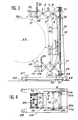
- - La figure 3 est une vue en élévation plus détaillée, d'un mode de réalisation particulier du dispositif.
- - La figure 4 est une vue schématique de dessus du dispositif illustré sur la figure 3.
- - Figures 1 and 2 schematically illustrate the means used in the device of the invention, shown in two different positions in contact with a convex surface, allowing a good understanding of the principle of the control of the movement produced according to the profile of this surface.
- - Figure 3 is a more detailed elevational view of a particular embodiment of the device.
- - Figure 4 is a schematic top view of the device illustrated in Figure 3.
Le dispositif schématiquement illustré sur les figures 1 et 2 se compose d'un bras de pantographe 1 lui-même formé de deux ciseaux successifs 2 et 3, dont les branches sont croisées et articulées mutuellement, respectivement autour d'axes horizontaux 4 et 5, perpendiculaires au plan de la figure. Les deux ciseaux sont en outre articulés l'un avec l'autre par leurs extrémités communes, réunies par des axes 6 et 7, parallèles aux axes 4 et 5.The device schematically illustrated in FIGS. 1 and 2 consists of a
Les extrémités opposées aux axes 6 et 7 des premiers ciseaux 2 sont à leur tour articulées autour d'axes 8 et 9, parallèles aux précédents, portés par un bâti 10. L'axe 8 est solidaire d'un écrou 11, comprenant un taraudage interne en prise avec le filetage externe d'une vis mère 12, s'étendant verticalement et supportée par le bâti 10 de telle sorte que la libre rotation de cette vis commandée par un motoréducteur 13, permette à l'écrou 11, lui-même immobilisé en rotation mais libre en translation de se déplacer sur le bâti de haut en bas ou vice versa en entraînant avec lui le bras de pantographe 1. L'axe 9 est solidarisé d'un manchon 14, apte à coulisser selon la direction de la vis 12, en fonction des débattements des branches croisées des premiers ciseaux 2. En variante, on peut intervertir le manchon 14 et l'écrou 11.The ends opposite
Les deux extrémités des seconds ciseaux 3, opposées aux axes 6 et 7, comportent de façon analogue deux axes parallèles 15 et 16, l'axe 15 étant, sur le schéma de principe de la figure 1, représenté associé à un objet 17, à déplacer au voisinage de la surface extérieure 18 d'un matériel ou d'une installation quelconque, cette surface présentant de préférence un profil convexe mais pouvant éventuellement être concave ou complexe. L'axe 16 comporte un guide 19, pouvant librement coulisser sur une tige 20 portée par l'objet 17, cette tige s'étendant parallèlement à la vis 12.The two ends of the
Conformément à l'invention, l'un au moins des axes du bras de pantographe 1, par exemple l'axe 4 autour duquel s'articulent les deux branches des premiers ciseaux 2, est monté à coulissement dans une rainure 21, ménagée dans une plaque 22 portée par le bâti 10 et s'étendant verticalement dans le plan du bras 1. La rainure 21 est une rainure continue, dont le profil est homothétique de celui de la surface 18 le long de laquelle doit se déplacer l'objet 17, ce déplacement étant réalisé consécutivement à celui de l'écrou 11 le long de la vis mère 12, d'une extrémité à l'autre de la rainure 21.According to the invention, at least one of the axes of the
Selon la position de l'écrou 11 sur la hauteur du bâti 10, on comprend en effet que la distance transversale qui sépare l'axe 4 de la vis 12 va varier, en ouvrant ou fermant progressivement les branches des premiers ciseaux 2 et, du fait de leur liaison articulée autour des axes 6 et 7, simultanément les branches des seconds ciseaux, en rapprochant ou écartant corrélativement l'objet 17 vis-à-vis de la référence fixe que constitue la vis 12 portée par le bâti 10. Le profil de la rainure 21 étant directement déduit de celui de la surface 18 par une homothétie selon un vecteur horizontal, l'objet 17 à déplacer peut ainsi être maintenu en permanence au contact de cette dernière, quelle que soit sa position par rapport à cette surface.Depending on the position of the
Au cours du déplacement de l'écrou 11, le manchon 14 d'une part, le guide 19 d'autre part, coulissent librement sur la vis mère 12 et la tige 20, en accommodant de façon permanente les variations des angles d'ouverture ou de fermeture des branches des ciseaux 2 et 3 autour de leurs axes 4 et 5 et en assurant une stabilité satisfaisante du bras de pantographe 1 et de l'objet à déplacer 17 monté en bout de celui-ci, tout en conservant à ce bras une orientation constante dans son plan confondu avec celui de la plaque 22 dans laquelle est ménagée la rainure 21.During the movement of the
On notera par ailleurs que la position relative des axes 15 et 16 aux extrémités des seconds ciseaux 3 peut être inversée, comme le montre la figure 2 par comparaison avec la figure 1. De même, l'objet 17 à déplacer au contact de la surface 18 n'est pas nécessairement disposé au droit de l'axe 15 mais peut être décalé pour se situer en un point quelconque de la tige 20, comme également illustré sur la figure 2.Note also that the relative position of the
Dans l'exemple de réalisation plus particulièrement illustré sur les figures 3 et 4, on retrouve les moyens essentiels décrits précédemment, affectés des mêmes chiffres de référence. La surface 18 est supposée ici être celle d'un cylindre 23 d'axe horizontal, constituant une pièce de grande dimension du genre notamment de celle que l'on peut rencontrer dans des unités de fabrication de matériels aéronautiques ou de matériels roulants, ou encore du type réservoir, citerne ou autres. L'objet 17 est constitué par une nacelle 24, dont est solidaire la tige 20 sur laquelle coulisse le guide 19, cette nacelle permettant d'assurer le déplacement d'un ouvrier 25 en tout point de la surface 18 pour intervenir sur celle-ci en procédant à n'importe quelle opération souhaitée d'usinage, de rectification, de finition, de maintenance ou de nettoyage. Bien entendu, il va de soi que la nacelle 24 pourrait de la même manière servir de support à un outil d'intervention, télécommandé ou non, pour la mise en oeuvre d'une opération quelconque sur la surface 18 de la pièce 23.In the embodiment more particularly illustrated in Figures 3 and 4, there are the essential means described above, assigned the same reference numbers. The
Le bâti 10 portant la vis 12 est monté sur un support horizontal 26 comprenant des étais 27, propres à maintenir le bâti et la plaque 22 dans un plan vertical. Le support peut, par exemple, comporter des roues 28 permettant de le déplacer sur le sol 29 pour amener l'ensemble au plus près de la pièce 23 avant que la nacelle 24 ne soit déplacée au voisinage de cette dernière. Bien entendu, le support peut être fixe, sans sortir du cadre de l'invention. Sur le dessin de la figure 3, le motoréducteur 13 a été représenté disposé sur le support 25, son arbre de sortie 30 entraînant un engrenage à pignons coniques 31 pour l'entraînement en rotation de la vis 12.The
Bien que la nacelle 24 puisse être supportée par un bras de pantographe 1 unique, on conçoit aisément que la stabilité du dispositif soit largement améliorée en disposant la nacelle en porte-à-faux sur deux bras de pantographe identiques et parallèles, respectivent 1a et 1b, schématiquement représentés sur la figure 4, les axes 4, 5, 6, 7, 8, 9, 15 et 16 étant communs à ces bras qui comportent deux écrous 11a et 11b coopérant avec deux vis d'entraînement 12a et l2b parallèles, portées par le bâti et entraînées en synchronisme à partir du motoréducteur 13.Although the
On réalise ainsi un dispositif de déplacement curviligne d'un objet au contact d'une surface notamment convexe, concave ou complexe, de conception très simple et dans lequel l'objet conserve une orientation constante, quel que soit le profil de cette surface, la rainure du guidage du bâti provoquant les mouvements de déplacement latéraux du bras de pantographe, sans nécessiter l'intervention d'ensembles électroniques complexes mémorisant les coordonnées de ce profil d'une extrémité à l'autre de la surface correspondante. Ce dispositif peut en outre facilement s'adapter à des profils de surface différents, par simple remplacement de la plaque portant la rainure image de chaque profil souhaité.A curvilinear displacement device of an object is thus produced in contact with a surface in particular convex, concave or complex, of very simple design and in which the object retains a constant orientation, whatever the profile of this surface, the groove of the guide of the frame causing the lateral displacement movements of the pantograph arm, without requiring the intervention of complex electronic assemblies memorizing the coordinates of this profile from one end to the other of the corresponding surface. This device can also easily adapt to different surface profiles, by simply replacing the plate carrying the image groove of each desired profile.
Bien entendu et comme il résulte déjà de ce qui précède, il va de soi que l'invention ne se limite pas au seul exemple de réalisation décrit et représenté ci-dessus ; elle en embrasse au contraire toutes les variantes susceptibles d'entrer dans le cadre des revendications qui suivent. Notamment, et selon la distance qui sépare le bâti de la surface contre laquelle l'objet est à déplacer, le bras de pantographe peut comporter un nombre de ciseaux articulés de proche en proche supérieur à deux pour autant qu'il présente une résistance mécanique suffisante pour permettre le support en porte à faux de l'objet à l'extrémité du bras.Of course and as it already follows from the above, it goes without saying that the invention is not limited to the single embodiment described and shown above; on the contrary, it embraces all the variants which may fall within the scope of the claims which follow. In particular, and depending on the distance which separates the frame from the surface against which the object is to be moved, the pantograph arm may include a number of scissors articulated step by step greater than two provided that it has sufficient mechanical strength to allow the object to be cantilevered at the end of the arm.
Claims (7)
Applications Claiming Priority (2)
| Application Number | Priority Date | Filing Date | Title |
|---|---|---|---|
| FR8907403 | 1989-06-05 | ||
| FR8907403A FR2647770B1 (en) | 1989-06-05 | 1989-06-05 | DEVICE FOR CURVILINALLY MOVING AN OBJECT IN CONTACT WITH A PARTICULARLY CONVEXED SURFACE |
Publications (2)
| Publication Number | Publication Date |
|---|---|
| EP0402216A1 true EP0402216A1 (en) | 1990-12-12 |
| EP0402216B1 EP0402216B1 (en) | 1993-01-20 |
Family
ID=9382370
Family Applications (1)
| Application Number | Title | Priority Date | Filing Date |
|---|---|---|---|
| EP90401491A Expired - Lifetime EP0402216B1 (en) | 1989-06-05 | 1990-06-01 | Device for the curvilinear motion of an object in contact with a surface, in particular with a convex surface |
Country Status (4)
| Country | Link |
|---|---|
| US (1) | US5109951A (en) |
| EP (1) | EP0402216B1 (en) |
| DE (2) | DE69000788T2 (en) |
| FR (1) | FR2647770B1 (en) |
Cited By (1)
| Publication number | Priority date | Publication date | Assignee | Title |
|---|---|---|---|---|
| DE4217698A1 (en) * | 1992-05-27 | 1993-12-02 | Hans Kremkau Jul Knappe Gmbh | Variable height work-surface for conveyor - has scissors-shaped variable struts with variable control rail |
Families Citing this family (7)
| Publication number | Priority date | Publication date | Assignee | Title |
|---|---|---|---|---|
| US5755306A (en) * | 1996-07-08 | 1998-05-26 | Genie Industries, Inc. | Personnel lift incorporating an outreach mechanism for an aerial work platform |
| US5901936A (en) * | 1997-08-25 | 1999-05-11 | Sandia Corporation | Six-degree-of-freedom multi-axes positioning apparatus |
| DE102005012497A1 (en) * | 2005-03-16 | 2006-09-21 | Aloys Wobben | platform |
| JP2007313603A (en) * | 2006-05-25 | 2007-12-06 | Honda Motor Co Ltd | Work auxiliary seat |
| US20100108441A1 (en) * | 2008-11-02 | 2010-05-06 | Morelli Vince | Adjustable work platform for pipe and casing stabbing operations |
| CN105291087A (en) * | 2015-11-30 | 2016-02-03 | 国网重庆市电力公司电力科学研究院 | Hot-line working robot |
| US10655345B2 (en) * | 2017-11-16 | 2020-05-19 | Tiong Bin Seow | Height accessible working platform with horizontally displaceable cradle |
Citations (2)
| Publication number | Priority date | Publication date | Assignee | Title |
|---|---|---|---|---|
| US3095061A (en) * | 1960-07-15 | 1963-06-25 | Louie E Gregory | Hydraulically operated lazy tongs structure |
| FR2156350A1 (en) * | 1971-10-14 | 1973-05-25 | Del Mar Eng Lab |
Family Cites Families (3)
| Publication number | Priority date | Publication date | Assignee | Title |
|---|---|---|---|---|
| US828709A (en) * | 1906-01-22 | 1906-08-14 | Amos B Buckland | Adjustable incandescent-light holder. |
| FR2384437A1 (en) * | 1977-03-21 | 1978-10-20 | Cepparo Louis | Working platform attachment for tractor - has three point linkage mounted frame with hydraulic cylinders to raise carriage and extend platforms |
| US4934643A (en) * | 1989-04-06 | 1990-06-19 | Militano Jr Martin T | Holder for screed rail |
-
1989
- 1989-06-05 FR FR8907403A patent/FR2647770B1/en not_active Expired - Lifetime
-
1990
- 1990-06-01 EP EP90401491A patent/EP0402216B1/en not_active Expired - Lifetime
- 1990-06-01 DE DE9090401491T patent/DE69000788T2/en not_active Expired - Fee Related
- 1990-06-01 DE DE199090401491T patent/DE402216T1/en active Pending
- 1990-12-27 US US02/634,736 patent/US5109951A/en not_active Expired - Fee Related
Patent Citations (2)
| Publication number | Priority date | Publication date | Assignee | Title |
|---|---|---|---|---|
| US3095061A (en) * | 1960-07-15 | 1963-06-25 | Louie E Gregory | Hydraulically operated lazy tongs structure |
| FR2156350A1 (en) * | 1971-10-14 | 1973-05-25 | Del Mar Eng Lab |
Cited By (1)
| Publication number | Priority date | Publication date | Assignee | Title |
|---|---|---|---|---|
| DE4217698A1 (en) * | 1992-05-27 | 1993-12-02 | Hans Kremkau Jul Knappe Gmbh | Variable height work-surface for conveyor - has scissors-shaped variable struts with variable control rail |
Also Published As
| Publication number | Publication date |
|---|---|
| DE402216T1 (en) | 1991-05-02 |
| DE69000788D1 (en) | 1993-03-04 |
| US5109951A (en) | 1992-05-05 |
| DE69000788T2 (en) | 1993-08-19 |
| EP0402216B1 (en) | 1993-01-20 |
| FR2647770B1 (en) | 1991-09-06 |
| FR2647770A1 (en) | 1990-12-07 |
Similar Documents
| Publication | Publication Date | Title |
|---|---|---|
| EP0010034B1 (en) | Vehicle able to propel itself with adhesion over any surface | |
| EP0194217B1 (en) | Industrial robots of the spherical type | |
| FR2513926A1 (en) | MECHANISM FOR CONTROLLING THE CONTROL ARM OF A ROBOT MANIPULATOR | |
| EP0402216B1 (en) | Device for the curvilinear motion of an object in contact with a surface, in particular with a convex surface | |
| EP2125301A2 (en) | Compact manipulation robot | |
| EP3400399B1 (en) | System for generating the movement of a support plate in six degrees of freedom | |
| EP0147301B1 (en) | Correction head with six degrees of freedom | |
| EP1854591A1 (en) | Parallel robot | |
| FR2607093A1 (en) | Vehicle capable of moving over a surface of any orientation | |
| WO1998053961A1 (en) | Robotized machine equipped with arm with symmetrical pantograph, for example for fruit picking or sorting diverse objects | |
| EP0490007A1 (en) | Device for moving an object in parallel with the curvature and in proximity to a surface of variable profile | |
| FR2700486A1 (en) | Indexed actuation head for automatic machine tools. | |
| FR2825445A1 (en) | METHOD FOR ORIENTING A HEXAPODE TURRET | |
| EP0247917B1 (en) | Mechanism for converting a reciprocating motion into a step-by-step rotary motion | |
| EP0307293B1 (en) | Coupling system for two bodies for instance a transportcar and a working station | |
| FR2739801A1 (en) | Manipulator with flat or three-dimensional trajectory suitable for high operating rate | |
| EP1380793B1 (en) | Mechanical device for the movement of a camera | |
| EP0508841A1 (en) | Windscreen wiper arm, in particular for high-speed vehicles | |
| EP1475511B1 (en) | Omni-directional drilling machine | |
| EP1065015A1 (en) | Apparatus for bending elongate metallic objects such as tubes | |
| EP0143134A1 (en) | Balancing means for robot arms | |
| FR2521037A1 (en) | ||
| EP0565615B1 (en) | Automatic painting machine particularly for painting the inside of a hollow body of quadrangular section and large size such as a shipping container | |
| FR2504441A1 (en) | INDUSTRIAL ROBOT HAVING MULTIPLE ROTATION AXES | |
| EP1528949A1 (en) | Device for physical exercises |
Legal Events
| Date | Code | Title | Description |
|---|---|---|---|
| PUAI | Public reference made under article 153(3) epc to a published international application that has entered the european phase |
Free format text: ORIGINAL CODE: 0009012 |
|
| AK | Designated contracting states |
Kind code of ref document: A1 Designated state(s): DE GB IT |
|
| 17P | Request for examination filed |
Effective date: 19901204 |
|
| ITCL | It: translation for ep claims filed |
Representative=s name: BARZANO' E ZANARDO MILANO S.P.A. |
|
| GBC | Gb: translation of claims filed (gb section 78(7)/1977) | ||
| DET | De: translation of patent claims | ||
| 17Q | First examination report despatched |
Effective date: 19920604 |
|
| GRAA | (expected) grant |
Free format text: ORIGINAL CODE: 0009210 |
|
| AK | Designated contracting states |
Kind code of ref document: B1 Designated state(s): DE GB IT |
|
| REF | Corresponds to: |
Ref document number: 69000788 Country of ref document: DE Date of ref document: 19930304 |
|
| ITF | It: translation for a ep patent filed |
Owner name: BARZANO' E ZANARDO MILANO S.P.A. |
|
| GBT | Gb: translation of ep patent filed (gb section 77(6)(a)/1977) |
Effective date: 19930422 |
|
| PLBE | No opposition filed within time limit |
Free format text: ORIGINAL CODE: 0009261 |
|
| STAA | Information on the status of an ep patent application or granted ep patent |
Free format text: STATUS: NO OPPOSITION FILED WITHIN TIME LIMIT |
|
| 26N | No opposition filed | ||
| PGFP | Annual fee paid to national office [announced via postgrant information from national office to epo] |
Ref country code: GB Payment date: 19940608 Year of fee payment: 5 |
|
| PGFP | Annual fee paid to national office [announced via postgrant information from national office to epo] |
Ref country code: DE Payment date: 19940831 Year of fee payment: 5 |
|
| PG25 | Lapsed in a contracting state [announced via postgrant information from national office to epo] |
Ref country code: GB Effective date: 19950601 |
|
| GBPC | Gb: european patent ceased through non-payment of renewal fee |
Effective date: 19950601 |
|
| PG25 | Lapsed in a contracting state [announced via postgrant information from national office to epo] |
Ref country code: DE Effective date: 19960301 |
|
| PG25 | Lapsed in a contracting state [announced via postgrant information from national office to epo] |
Ref country code: IT Free format text: LAPSE BECAUSE OF NON-PAYMENT OF DUE FEES;WARNING: LAPSES OF ITALIAN PATENTS WITH EFFECTIVE DATE BEFORE 2007 MAY HAVE OCCURRED AT ANY TIME BEFORE 2007. THE CORRECT EFFECTIVE DATE MAY BE DIFFERENT FROM THE ONE RECORDED. Effective date: 20050601 |