EP0400368B1 - Valve de remplissage pour remplir des doses de produits fluides - Google Patents
Valve de remplissage pour remplir des doses de produits fluides Download PDFInfo
- Publication number
- EP0400368B1 EP0400368B1 EP90108784A EP90108784A EP0400368B1 EP 0400368 B1 EP0400368 B1 EP 0400368B1 EP 90108784 A EP90108784 A EP 90108784A EP 90108784 A EP90108784 A EP 90108784A EP 0400368 B1 EP0400368 B1 EP 0400368B1
- Authority
- EP
- European Patent Office
- Prior art keywords
- valve
- filling
- tappet
- vibration
- valve tappet
- Prior art date
- Legal status (The legal status is an assumption and is not a legal conclusion. Google has not performed a legal analysis and makes no representation as to the accuracy of the status listed.)
- Expired - Lifetime
Links
Images


Classifications
-
- B—PERFORMING OPERATIONS; TRANSPORTING
- B65—CONVEYING; PACKING; STORING; HANDLING THIN OR FILAMENTARY MATERIAL
- B65B—MACHINES, APPARATUS OR DEVICES FOR, OR METHODS OF, PACKAGING ARTICLES OR MATERIALS; UNPACKING
- B65B39/00—Nozzles, funnels or guides for introducing articles or materials into containers or wrappers
- B65B39/001—Nozzles, funnels or guides for introducing articles or materials into containers or wrappers with flow cut-off means, e.g. valves
- B65B39/004—Nozzles, funnels or guides for introducing articles or materials into containers or wrappers with flow cut-off means, e.g. valves moving linearly
Definitions
- the invention relates to a filling valve for filling portions of flowable products, in particular foodstuffs with lumpy components, from a filling container of a filling and closing machine, with an axially movable valve tappet arranged in a mouthpiece and designed as a valve slide (see, for example, EP-A-0 267 458).
- the invention has for its object to provide a filling valve for portion-wise filling of flowable products of the type mentioned, with which a dripping or stringing is reliably prevented when filling flowable products with a small device structure.
- valve tappet is connected to a vibration unit with which in the closed position the valve tappet can be set in vibration in the axial direction with a stroke in which the closing function of the valve tappet is maintained.
- the vibration unit can be in operative connection either directly on a valve rod of the valve tappet or via a deflection mechanism with the valve tappet. In the latter case, the vibration unit can be arranged between a cylinder-piston unit for opening and closing the filling valve and a free arm of the reversing mechanism, or else directly on a bridge-like bearing part of the reversing mechanism.
- the vibration unit can be pneumatic, electro-pneumatic or electrical.
- Valve tappet in the direction of the closing movement makes it possible to hold the valve tappet in a precisely defined position at the end of the oscillation process. This is important because the valve tappet must have a certain starting position for the subsequent opening or closing movement.
- a product tank 1 is connected to a filling device 2, which has a housing with a mouthpiece 3.
- a suction valve 4 is arranged in the housing and is connected via an actuating lever 5 to a drive device 6, not shown in detail.
- the actuating lever 5 can be moved in the direction of the double arrow 7.
- a filling valve 8 which is composed of a valve tappet 9 designed as a valve slide, a valve rod 11 and likewise an actuating lever 10; the latter in turn leads to the drive device 6.
- the drive of the filling valve is explained in more detail below with reference to FIG. 4.
- In the area of the valve rod 11 there is a metering piston 12 which is guided to move back and forth in the direction of the double arrow 13.
- the valve tappet 9 is designed as a so-called cutting tappet and, as can also be seen from FIGS. 2 and 3, is guided in a tappet guide 14 which in turn is inserted in the mouthpiece 3.
- the Tappet guide 14 has lateral openings 15 through which, when the valve tappet 9 is raised, the product can flow through the lower outlet opening 16 into a vessel 17 located underneath.
- the valve tappet 9 is moved rapidly downward via the valve rod 11 and the side passage openings 15 are closed, as shown in FIG. 3. From the same figure it can be seen that 9 product residues can stick to the end face 18 of the valve lifter. In order to shake them off or to distribute them evenly on the underside of the tappet, the valve tappet 9 is set in vibration.
- the vibration stroke can be 5 to 10 mm. It is understood that the valve tappet 9 must not open the through openings 15.
- the vibration frequency and the number of vibrations vary depending on the product. Good results for products with lumpy goods have been obtained at 30 to 40 Hz and with an oscillation number of preferably 0.5 to 4 oscillations. Half an oscillation is to be understood as an upward jolt.
- the drive for generating the vibration of the valve lifter 9 can be achieved in a suitable manner.
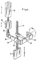
- a possible drive option is shown in FIG. 4.
- the valve tappet 9 is connected to a deflection mechanism 19 by means of the valve rod 11.
- This has a bridge-like bearing part 22 which is pivotally mounted about an essentially horizontal axis 23.
- the bearing part 22 also has an actuating lever 21 for the valve rod 11 and a freely projecting arm 24.
- the filling valve is thus opened and closed by a single device and, after the closing process, the valve tappet 9 is set into the vertical vibration movement by actuating the vibration unit 26.
- the vibration unit is mounted on the bridge-like bearing part 22 and carries out the pivoting movement during the opening or closing process.
- the operating lever 21 is pivotally mounted and driven in the vibration unit. During the opening or closing movement, the actuating lever 21 is held in a defined position in the vibration unit.
- FIG. 6 shows a modified embodiment of the filling device 2.
- the product tank 1 and the suction valve 4 with its drive are arranged laterally offset. This results in the possibility of arranging the vibration unit 26 and the cylinder-piston unit 27 for driving the valve tappet 9 directly on its valve rod 11.
Claims (7)
- Valve de remplissage pour le soutirage par portions de produits coulants, en particulier des produits alimentaires avec des ingrédients en morceaux, depuis un récipient de soutirage (1) d'une machine de remplissage et de sertissage, avec un poussoir de valve (9) mobile axialement disposé dans un ajutage (3) et réalisé sous forme de coulisse de valve, caractérisée en ce que le poussoir de valve (9) est relié à une unité de vibration (26) par laquelle le poussoir de valve (9) en position de fermeture peut être mis en vibration en direction axiale avec une course avec laquelle la fonction de fermeture du poussoir de valve (9) reste maintenue.
- Valve de remplissage selon la revendication 1,
caractérisée en ce que le dispositif de vibration présente une unité de vibration (26) qui est disposée sur une tige de valve (11) du poussoir de valve (9). - Valve de remplissage selon la revendication 1,
caractérisée en ce que le dispositif de vibration présente une unité de vibration (26) qui est en liaison active avec le poussoir de valve (9) par l'intermédiaire d'un mécanisme de renvoi (19). - Valve de remplissage selon la revendication 3,
caractérisée en ce que l'unité de vibration (26) est disposée entre un vérin (27) d'ouverture et fermeture de la valve de remplissage et un bras (24) du mécanisme de renvoi (19) (figure 4). - Valve de remplissage selon la revendication 3,
caractérisée en ce que l'unité de vibration (26) est rapportée sur une pièce de support (22) en forme de pont du mécanisme de renvoi (19) (figure 5). - Valve de remplissage selon la revendication 5,
caractérisée en ce que la pièce de support (22) est montée oscillante autour d'un axe (23) sensiblement horizontal et est reliée à la tige de valve (11) du poussoir de valve (9) au moyen d'un bras (21). - Valve de remplissage selon une ou plusieurs des revendications 2 à 6,
caractérisée en ce que le poussoir de valve (9) est réalisé sous forme d'un poussoir de coupe guidé dans un guidage de poussoir (14) avec des ouvertures de passage (15).
Priority Applications (1)
| Application Number | Priority Date | Filing Date | Title |
|---|---|---|---|
| AT90108784T ATE84483T1 (de) | 1989-06-02 | 1990-05-10 | Fuellventil zum portionsweisen abfuellen von fliessfaehigen produkten. |
Applications Claiming Priority (2)
| Application Number | Priority Date | Filing Date | Title |
|---|---|---|---|
| DE3918008 | 1989-06-02 | ||
| DE3918008A DE3918008C1 (fr) | 1989-06-02 | 1989-06-02 |
Publications (2)
| Publication Number | Publication Date |
|---|---|
| EP0400368A1 EP0400368A1 (fr) | 1990-12-05 |
| EP0400368B1 true EP0400368B1 (fr) | 1993-01-13 |
Family
ID=6381922
Family Applications (1)
| Application Number | Title | Priority Date | Filing Date |
|---|---|---|---|
| EP90108784A Expired - Lifetime EP0400368B1 (fr) | 1989-06-02 | 1990-05-10 | Valve de remplissage pour remplir des doses de produits fluides |
Country Status (9)
| Country | Link |
|---|---|
| US (1) | US5105861A (fr) |
| EP (1) | EP0400368B1 (fr) |
| JP (1) | JP2536953B2 (fr) |
| AT (1) | ATE84483T1 (fr) |
| AU (1) | AU635177B2 (fr) |
| CA (1) | CA2018033C (fr) |
| DE (2) | DE3918008C1 (fr) |
| ES (1) | ES2038017T3 (fr) |
| ZA (1) | ZA903810B (fr) |
Cited By (1)
| Publication number | Priority date | Publication date | Assignee | Title |
|---|---|---|---|---|
| DE102013109633A1 (de) | 2013-09-04 | 2015-03-05 | Sig Technology Ag | Vorrichtung zur Steuerung der Durchflussmenge |
Families Citing this family (11)
| Publication number | Priority date | Publication date | Assignee | Title |
|---|---|---|---|---|
| DE9312817U1 (de) * | 1993-08-26 | 1993-12-16 | Hassia Verpackung Ag | Schließ- und Öffnungsvorrichtung für Abfüllmaschinen zum Abfüllen von fließfähigen Produkten |
| US6561387B1 (en) | 2002-03-04 | 2003-05-13 | Larry R. Slawson | Material transport system and apparatus for conveying water softener salt to a brine tank |
| DE602004030323D1 (de) * | 2003-03-20 | 2011-01-13 | Ricoh Co Ltd | Vorrichtung und verfahren zur pulverfüllung |
| US20040188330A1 (en) * | 2003-03-26 | 2004-09-30 | Slawson Larry R | Apparatus and system for automatically ordering salt and monitoring the salt in a brine tank |
| DE102008020751A1 (de) | 2008-04-22 | 2009-10-29 | Sig Technology Ltd. | Verfahren und Vorrichtung zum Dosieren von Produkten |
| US7762290B2 (en) | 2008-11-06 | 2010-07-27 | Poet Research, Inc. | System for loading particulate matter into a transport container |
| JP6051612B2 (ja) * | 2012-06-22 | 2016-12-27 | 凸版印刷株式会社 | 液体飲料の充填方法 |
| DE102012111552A1 (de) * | 2012-11-28 | 2014-05-28 | Krones Ag | Füllorgan zum Befüllen eines Behälters mit einem Füllprodukt |
| JP5996417B2 (ja) * | 2012-12-20 | 2016-09-21 | 東洋自動機株式会社 | 容器への粉体充填装置 |
| JP6315459B2 (ja) * | 2014-06-10 | 2018-04-25 | 鈴茂器工株式会社 | 食材処理装置および食材包装装置 |
| US20180037351A1 (en) * | 2016-08-08 | 2018-02-08 | The Procter & Gamble Company | Fluid Filling Nozzle, Apparatus, and Method of Filling a Container with a Fluid |
Family Cites Families (9)
| Publication number | Priority date | Publication date | Assignee | Title |
|---|---|---|---|---|
| US2996928A (en) * | 1957-11-25 | 1961-08-22 | Orla E Watson | Valve operator |
| DE1123545B (de) * | 1959-03-07 | 1962-02-08 | Bindler Maschinenfabrik Geb | Dosiervorrichtung fuer Schokoladenmasse u. dgl. |
| US3205920A (en) * | 1962-07-18 | 1965-09-14 | Cozzoli Machine | Apparatus for charging containers with liquid |
| ATE29465T1 (de) * | 1980-07-24 | 1987-09-15 | Simon Solitec Ltd | Gutabgabeeinrichtung. |
| DE3229162C2 (de) * | 1982-08-04 | 1986-01-02 | Bausch + Ströbel, Maschinenfabrik GmbH + Co, 7174 Ilshofen | Flüssigkeits-Abfüllnadel |
| SE460598B (sv) * | 1986-10-29 | 1989-10-30 | Pkl Verpackungssysteme Gmbh | Munstycke med minst en tillslutbar munstycksoeppning |
| DE3704901A1 (de) * | 1987-02-17 | 1988-08-25 | Lieder Maschinenbau Gmbh & Co | Fuellventil |
| US4789012A (en) * | 1987-03-23 | 1988-12-06 | Minnesota Mining And Manufacturing Company | Injection head for filling dispenser that meters proportionate increments of dissimilar materials |
| JPH0232905A (ja) * | 1988-07-12 | 1990-02-02 | Meiwa Kikai Kk | ロータリー式食品充填機 |
-
1989
- 1989-06-02 DE DE3918008A patent/DE3918008C1/de not_active Expired - Fee Related
-
1990
- 1990-05-10 ES ES199090108784T patent/ES2038017T3/es not_active Expired - Lifetime
- 1990-05-10 EP EP90108784A patent/EP0400368B1/fr not_active Expired - Lifetime
- 1990-05-10 AT AT90108784T patent/ATE84483T1/de not_active IP Right Cessation
- 1990-05-10 DE DE9090108784T patent/DE59000746D1/de not_active Expired - Fee Related
- 1990-05-17 ZA ZA903810A patent/ZA903810B/xx unknown
- 1990-05-22 AU AU55827/90A patent/AU635177B2/en not_active Ceased
- 1990-05-30 US US07/530,650 patent/US5105861A/en not_active Expired - Fee Related
- 1990-05-31 JP JP2140126A patent/JP2536953B2/ja not_active Expired - Fee Related
- 1990-06-01 CA CA002018033A patent/CA2018033C/fr not_active Expired - Fee Related
Cited By (1)
| Publication number | Priority date | Publication date | Assignee | Title |
|---|---|---|---|---|
| DE102013109633A1 (de) | 2013-09-04 | 2015-03-05 | Sig Technology Ag | Vorrichtung zur Steuerung der Durchflussmenge |
Also Published As
| Publication number | Publication date |
|---|---|
| ZA903810B (en) | 1991-03-27 |
| JPH0398802A (ja) | 1991-04-24 |
| AU635177B2 (en) | 1993-03-11 |
| DE3918008C1 (fr) | 1990-09-27 |
| US5105861A (en) | 1992-04-21 |
| CA2018033C (fr) | 1999-01-05 |
| JP2536953B2 (ja) | 1996-09-25 |
| ATE84483T1 (de) | 1993-01-15 |
| AU5582790A (en) | 1990-12-06 |
| CA2018033A1 (fr) | 1990-12-02 |
| ES2038017T3 (es) | 1993-07-01 |
| EP0400368A1 (fr) | 1990-12-05 |
| DE59000746D1 (de) | 1993-02-25 |
Similar Documents
| Publication | Publication Date | Title |
|---|---|---|
| EP0400368B1 (fr) | Valve de remplissage pour remplir des doses de produits fluides | |
| DE3336251A1 (de) | Klappenantriebsvorrichtung | |
| DE1279360B (de) | Zufuehrvorrichtung fuer selbsttaetige Waagen | |
| DE2311728C2 (de) | Absackvorrichtung | |
| EP0188737A2 (fr) | Appareil de production de colloides de fluides | |
| DE3543504A1 (de) | Fuellpumpe zum eindosieren von fluessigen bis pastoesen produkten | |
| DE1151723B (de) | Vorrichtung zum Dekorieren von Pralinen, Gebaeck u. dgl. | |
| DE1812291B2 (de) | Vorrichtung zum bilden weitgehend gewichtsgleicher tabakportionen | |
| DE2509659A1 (de) | Vorrichtung mit drehbarem kopf fuer die zufuhr von zigaretten zu den beschickungstrichtern von hochleistungszigarettenverpackungsmaschinen | |
| EP0540944B1 (fr) | Pompe doseuse pour produits à haute viscosité | |
| DE4316842A1 (de) | Schneidvorrichtung für zähflüssige Klumpen | |
| DE4119559A1 (de) | Mechanische vorrichtung zur ausfuehrung des arbeitszyklus eines automatischen apparates fuer die zubereitung von kaffee oder von anderen heissen getraenken | |
| DE3630077A1 (de) | Vorrichtung zum gleichzeitigen dosierten abfuellen von fluessigen oder weichplastischen stoffen, wie butter, margarine, pasten oder dgl. ueber mundstuecke in benachbart zueinander angeordnete behaelter | |
| DE3624592C2 (fr) | ||
| CH440872A (de) | Schliessvorrichtung, insbesondere für Autoklaven | |
| DE1123545B (de) | Dosiervorrichtung fuer Schokoladenmasse u. dgl. | |
| DE2824680C2 (de) | Vorrichtung zum Dosieren und Abfüllen insbesondere hochviskoser Medien | |
| DE19845702C2 (de) | Rühr- und Mischeinrichtung für einen Vorratsbehälter mit Dosiereinrichtung für zähflüssige Stoffe, wie Gießharz | |
| DE905107C (de) | Vorrichtung zum Pressen und Verpacken von losem, insbesondere faserigem Matrrial | |
| DE3509087C2 (fr) | ||
| DE4306245C2 (de) | Wägemaschine | |
| DD137880B1 (de) | Vorrichtung zum abfuellen von pastoesen guetern,insbesondere wurst | |
| CH369062A (de) | Apparatur zur Aufteilung von langen Nudeln in bestimmte Gewichtsportionen | |
| AT391568B (de) | Warenausgabeautomat | |
| DE2218864B2 (de) | Vorrichtung zum dosierten Abfüllen von Flüssigkeiten wie Milch u.dgl |
Legal Events
| Date | Code | Title | Description |
|---|---|---|---|
| PUAI | Public reference made under article 153(3) epc to a published international application that has entered the european phase |
Free format text: ORIGINAL CODE: 0009012 |
|
| AK | Designated contracting states |
Kind code of ref document: A1 Designated state(s): AT BE CH DE DK ES FR GB IT LI NL SE |
|
| 17P | Request for examination filed |
Effective date: 19901222 |
|
| 17Q | First examination report despatched |
Effective date: 19920612 |
|
| GRAA | (expected) grant |
Free format text: ORIGINAL CODE: 0009210 |
|
| AK | Designated contracting states |
Kind code of ref document: B1 Designated state(s): AT BE CH DE DK ES FR GB IT LI NL SE |
|
| PG25 | Lapsed in a contracting state [announced via postgrant information from national office to epo] |
Ref country code: BE Effective date: 19930113 Ref country code: DK Effective date: 19930113 Ref country code: GB Effective date: 19930113 |
|
| REF | Corresponds to: |
Ref document number: 84483 Country of ref document: AT Date of ref document: 19930115 Kind code of ref document: T |
|
| REF | Corresponds to: |
Ref document number: 59000746 Country of ref document: DE Date of ref document: 19930225 |
|
| ET | Fr: translation filed | ||
| ITF | It: translation for a ep patent filed |
Owner name: SOCIETA' ITALIANA BREVETTI S.P.A. |
|
| REG | Reference to a national code |
Ref country code: ES Ref legal event code: FG2A Ref document number: 2038017 Country of ref document: ES Kind code of ref document: T3 |
|
| GBV | Gb: ep patent (uk) treated as always having been void in accordance with gb section 77(7)/1977 [no translation filed] |
Effective date: 19930113 |
|
| PLBI | Opposition filed |
Free format text: ORIGINAL CODE: 0009260 |
|
| 26 | Opposition filed |
Opponent name: AB TETRA PAK Effective date: 19931012 |
|
| NLR1 | Nl: opposition has been filed with the epo |
Opponent name: AB TETRA PAK |
|
| EAL | Se: european patent in force in sweden |
Ref document number: 90108784.1 |
|
| PLBN | Opposition rejected |
Free format text: ORIGINAL CODE: 0009273 |
|
| STAA | Information on the status of an ep patent application or granted ep patent |
Free format text: STATUS: OPPOSITION REJECTED |
|
| 27O | Opposition rejected |
Effective date: 19950227 |
|
| NLR2 | Nl: decision of opposition | ||
| PGFP | Annual fee paid to national office [announced via postgrant information from national office to epo] |
Ref country code: AT Payment date: 19980520 Year of fee payment: 9 |
|
| PG25 | Lapsed in a contracting state [announced via postgrant information from national office to epo] |
Ref country code: AT Free format text: LAPSE BECAUSE OF NON-PAYMENT OF DUE FEES Effective date: 19990510 |
|
| PGFP | Annual fee paid to national office [announced via postgrant information from national office to epo] |
Ref country code: NL Payment date: 20050524 Year of fee payment: 16 Ref country code: SE Payment date: 20050524 Year of fee payment: 16 |
|
| PG25 | Lapsed in a contracting state [announced via postgrant information from national office to epo] |
Ref country code: SE Free format text: LAPSE BECAUSE OF NON-PAYMENT OF DUE FEES Effective date: 20060511 |
|
| PG25 | Lapsed in a contracting state [announced via postgrant information from national office to epo] |
Ref country code: NL Free format text: LAPSE BECAUSE OF NON-PAYMENT OF DUE FEES Effective date: 20061201 |
|
| EUG | Se: european patent has lapsed | ||
| NLV4 | Nl: lapsed or anulled due to non-payment of the annual fee |
Effective date: 20061201 |
|
| PGFP | Annual fee paid to national office [announced via postgrant information from national office to epo] |
Ref country code: CH Payment date: 20070531 Year of fee payment: 18 |
|
| PGFP | Annual fee paid to national office [announced via postgrant information from national office to epo] |
Ref country code: ES Payment date: 20070605 Year of fee payment: 18 |
|
| PGFP | Annual fee paid to national office [announced via postgrant information from national office to epo] |
Ref country code: DE Payment date: 20070720 Year of fee payment: 18 |
|
| PGFP | Annual fee paid to national office [announced via postgrant information from national office to epo] |
Ref country code: IT Payment date: 20070531 Year of fee payment: 18 |
|
| PGFP | Annual fee paid to national office [announced via postgrant information from national office to epo] |
Ref country code: FR Payment date: 20070531 Year of fee payment: 18 |
|
| PLAB | Opposition data, opponent's data or that of the opponent's representative modified |
Free format text: ORIGINAL CODE: 0009299OPPO |
|
| REG | Reference to a national code |
Ref country code: CH Ref legal event code: PL |
|
| PG25 | Lapsed in a contracting state [announced via postgrant information from national office to epo] |
Ref country code: CH Free format text: LAPSE BECAUSE OF NON-PAYMENT OF DUE FEES Effective date: 20080531 Ref country code: LI Free format text: LAPSE BECAUSE OF NON-PAYMENT OF DUE FEES Effective date: 20080531 |
|
| REG | Reference to a national code |
Ref country code: FR Ref legal event code: ST Effective date: 20090119 |
|
| PG25 | Lapsed in a contracting state [announced via postgrant information from national office to epo] |
Ref country code: FR Free format text: LAPSE BECAUSE OF NON-PAYMENT OF DUE FEES Effective date: 20080602 Ref country code: DE Free format text: LAPSE BECAUSE OF NON-PAYMENT OF DUE FEES Effective date: 20081202 |
|
| REG | Reference to a national code |
Ref country code: ES Ref legal event code: FD2A Effective date: 20080512 |
|
| PG25 | Lapsed in a contracting state [announced via postgrant information from national office to epo] |
Ref country code: IT Free format text: LAPSE BECAUSE OF NON-PAYMENT OF DUE FEES Effective date: 20080510 |
|
| PG25 | Lapsed in a contracting state [announced via postgrant information from national office to epo] |
Ref country code: ES Free format text: LAPSE BECAUSE OF NON-PAYMENT OF DUE FEES Effective date: 20080512 |