EP0399883B1 - Beschickungs- und Entleerungsvorrichtung für einen Plattengefrierapparat - Google Patents
Beschickungs- und Entleerungsvorrichtung für einen Plattengefrierapparat Download PDFInfo
- Publication number
- EP0399883B1 EP0399883B1 EP90401334A EP90401334A EP0399883B1 EP 0399883 B1 EP0399883 B1 EP 0399883B1 EP 90401334 A EP90401334 A EP 90401334A EP 90401334 A EP90401334 A EP 90401334A EP 0399883 B1 EP0399883 B1 EP 0399883B1
- Authority
- EP
- European Patent Office
- Prior art keywords
- chains
- pusher
- pinions
- products
- conveyor
- Prior art date
- Legal status (The legal status is an assumption and is not a legal conclusion. Google has not performed a legal analysis and makes no representation as to the accuracy of the status listed.)
- Expired - Lifetime
Links
- 239000003638 chemical reducing agent Substances 0.000 claims description 2
- 239000000463 material Substances 0.000 claims 1
- 238000011084 recovery Methods 0.000 abstract description 3
- 230000004888 barrier function Effects 0.000 description 4
- 238000006073 displacement reaction Methods 0.000 description 2
- 230000001960 triggered effect Effects 0.000 description 2
- 238000011144 upstream manufacturing Methods 0.000 description 2
- 230000002159 abnormal effect Effects 0.000 description 1
- 230000015572 biosynthetic process Effects 0.000 description 1
- 239000000969 carrier Substances 0.000 description 1
- 238000006243 chemical reaction Methods 0.000 description 1
- 239000012809 cooling fluid Substances 0.000 description 1
- 238000007710 freezing Methods 0.000 description 1
- 230000008014 freezing Effects 0.000 description 1
- 235000013611 frozen food Nutrition 0.000 description 1
- 238000005259 measurement Methods 0.000 description 1
- 210000000056 organ Anatomy 0.000 description 1
- 230000035939 shock Effects 0.000 description 1
- 238000010257 thawing Methods 0.000 description 1
- 238000004804 winding Methods 0.000 description 1
Images

Classifications
-
- F—MECHANICAL ENGINEERING; LIGHTING; HEATING; WEAPONS; BLASTING
- F25—REFRIGERATION OR COOLING; COMBINED HEATING AND REFRIGERATION SYSTEMS; HEAT PUMP SYSTEMS; MANUFACTURE OR STORAGE OF ICE; LIQUEFACTION SOLIDIFICATION OF GASES
- F25D—REFRIGERATORS; COLD ROOMS; ICE-BOXES; COOLING OR FREEZING APPARATUS NOT OTHERWISE PROVIDED FOR
- F25D31/00—Other cooling or freezing apparatus
- F25D31/001—Plate freezers
-
- F—MECHANICAL ENGINEERING; LIGHTING; HEATING; WEAPONS; BLASTING
- F25—REFRIGERATION OR COOLING; COMBINED HEATING AND REFRIGERATION SYSTEMS; HEAT PUMP SYSTEMS; MANUFACTURE OR STORAGE OF ICE; LIQUEFACTION SOLIDIFICATION OF GASES
- F25D—REFRIGERATORS; COLD ROOMS; ICE-BOXES; COOLING OR FREEZING APPARATUS NOT OTHERWISE PROVIDED FOR
- F25D25/00—Charging, supporting, and discharging the articles to be cooled
- F25D25/04—Charging, supporting, and discharging the articles to be cooled by conveyors
Definitions
- the present invention relates to plate freezers consisting of a stack of horizontal, hollow plates, in which a cooling fluid circulates and which are placed inside an insulating cabin comprising on two opposite sides openings for loading the products to freezing and unloading frozen products, means for vertically moving the stack of plates and bringing each plate one after the other at said openings, and means for loading the products to be frozen onto the plate located at these openings, through one of them, and to discharge the frozen products through the other opening.
- a deep-freezer is described, for example, in the document GB-A-2,053,831.
- the products to be frozen are brought to the loading opening by a horizontal endless belt conveyor and are loaded by means of a pusher.
- the products are stored side by side on the conveyor, the length of the row being equal to the useful width of the plates, and all the products in the row are loaded at the same time on the plate.
- the unloading of frozen products and the loading of products to be frozen are carried out simultaneously, the introduction of a row of products to be frozen causing the translation of all the products on the plate towards the unloading opening and expulsion to across it from the row closest to it.
- the stroke of the pusher can be relatively short. But generally the pusher is also used to completely empty the freezer before stopping, for example to defrost it; the stroke of the pusher must then be greater than the length of the plates (3 to 4 m). It is therefore not possible to use conventional jacks to actuate the pusher and special chains are generally used which can only bend in one direction, from their rectilinear position, so that they are capable of exert not only tensile forces but also pushing forces, under certain conditions of application of the forces. These chains are moved, like racks, by pinions which mesh with their rectilinear and horizontal part whose end is coupled to the pusher.
- the chains are guided in upwardly curved sheaths to reduce bulk. Since the sprockets are only engaged with the chains by a tooth or two, the forces which can be transmitted to the pusher are limited. However, it is sometimes necessary to exert significant efforts to remove the frozen products from the plate, before a new loading, and this may prove to be impossible with known devices.
- the object of the present invention is to remedy this drawback and to provide a device capable of exerting a significant force on the pusher without having to oversize the organs of the device and making it possible to control this effort and, if necessary, to limit it to an acceptable value.
- the device which is the subject of the present invention is characterized in that the chains have short links so that they can be wound around the pinions and are engaged therewith over a quarter of a circle approximately, and in that the pinions are fixed on a shaft which is rotated by a gear motor-brake unit mounted floating on said shaft and comprising a torque recovery arm connected to the chassis of the freezer by a dynamometer.
- the dynamometer will advantageously be constituted by a pneumatic cylinder and means for measuring the pressure in the cylinder will be provided to determine the torque of the motor and, consequently, the force exerted by the pusher.
- Control means of said jack may also be provided to cause the rotation of the shaft, the brake of said group being applied, and, consequently, the advance of the pusher over a short distance.
- the chains are supported by guides, in the portion of their path between the pinions and the loading conveyor, these guides are mounted to rotate around the axis of the pinions, and means are provided. to rotate these guides around said axis and lift the chains and the pusher.
- These guides can, for example, be fixed on a tube coaxial with the pinion shaft and the rotation of which, relative to the shaft, can be controlled by a jack coupled to an arm integral with said tube.
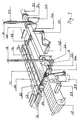
- the device used to load the products onto the plates comprises a pusher 14 constituted by a horizontal bar whose length is approximately equal to the useful width of the plates and which is coupled, by articulations, to two chains 16 which are wound on two sprockets 18 and are then guided in vertical sheaths shown schematically at 20.
- the length of the chains must be sufficient to allow the pusher to move over the entire length of the plates, which can exceed 3 m.
- the sheaths 20 must have a corresponding length and, to reduce their bulk, are bent forward and then downward, in the form of a hairpin.
- the pinions 18 are keyed onto a shaft 22 mounted on bearings 24 fixed to the chassis of the device.
- this chassis has not been shown nor, consequently, the means for fixing the bearings and the other members which are integral therewith; these means are conventional and their description is not necessary for understanding the invention.
- the shaft 22 can be rotated by a two-speed motor - reducer - brake group 26, mounted floating on one end of the shaft and comprising a torque recovery arm linked to the chassis of the device by a pneumatic cylinder 28.
- An encoder 30 mounted at the other end of the shaft 22 makes it possible to measure the number of turns and fractional turns made by the shaft 22 and, consequently, the displacements of the pusher 14.
- the chains 16 are formed of links 32 having abutment surfaces 34 which, when the links are aligned, are in contact with each other and allow the relative rotation of the links only in one direction, that allowing the winding the chains around the sprockets 18.
- the chains 16 are provided with rollers 36 mounted on the axes of articulations 38 of the links and with which the teeth of the pinions engage.
- the part of the sprockets on which the chain is wound is surrounded by a fixed ramp 40 in an arc of circle on which the rollers roll and which takes up the reactions of the chain (only one of these ramps has been shown in FIG. 1).
- the chains 16 also include sliding pads 42 which support the chains in the horizontal portion of their course. These pads are constituted by plastic plates with low coefficient of friction which are mounted on the articulation axes of the links on the two sides of the chain and whose height is greater than that of the links so that they keep them away from the surfaces on which they slide.
- rollers 36 and the pads 42 cooperate with a track and sliding surfaces, respectively, which guide the chains (FIG. 3).
- the chains are supported by rectilinear guides 44 on which the pads 42 slide.
- These guides are integral with a tube 46 rotatably mounted on the shaft 22 and the rotation of which can be controlled by a jack 48 coupled, by means of a rod and lever system, to an arm 50 fixed to the tube.
- the rotation of the tube and the guides makes it possible to lift the chains and the pusher to move them away from the plane of the conveyor 12. It is possible, thanks to this improvement, to bring products to be frozen to the loading position, by means of the conveyor 12 , during the return stroke of the pusher, which saves time and reduces the duration of the loading cycle.
- the pusher 14 is provided at its ends with rollers 52 which keep it at a short distance from the surfaces above which it moves, to eliminate friction.
- the freezer operates continuously and, in steady state, the plates are always loaded.
- the plates are always loaded.
- it is necessary simultaneously to discharge the frozen products which are there.
- frost the products frozen food sticks to the plates and it is necessary to peel them off before they can be unloaded by sliding them on the plate.
- This operation is carried out by means of the pusher 14 which is brought from its retracted position, below the conveyor 12, into contact with the first row of products located on the plate, then moved a few centimeters beyond this position.
- the position of the pusher 14 is determined by means of the encoder 30 which controls the reversal of the direction of rotation of the motor 26, when the pusher reaches the limit position, predetermined for this operation, and stops the motor when the pusher is again in its initial position.
- the effort required to take off the products is determined from a measurement of the pressure in the jack 28; if this pressure exceeds a predetermined value, the power supply to the motor 26 can be cut and an alarm triggered to warn the operator of an abnormal situation. Since it is easier to take off by applying shocks rather than a continuous push on frozen products, it may be advantageous to move the pusher in an alternating movement, by means of the jack 28, after the 'having brought into contact with the products by means of group 26.
- a solenoid valve with manual or automatic control allows this use of the jack 28.
- the conveyor 12 is stopped and not loaded. It can be started during the return race, as soon as the pusher is sufficiently retracted to allow the passage of a row of products.
- the conveyor 12 is supplied with products to be frozen by a conveyor located upstream.
- the stopping of the row 11 against the stop 54 controls the starting of the motor 26 which moves the pusher forward; the latter pushes row 11, sliding it onto the conveyor and then onto the sheet 13 until it comes into contact with the first row of frozen products 58 located on the plate.
- the advance of the pusher then causes the displacement of all the rows of frozen products on the plate and the expulsion of the last row through the unloading opening provided on the rear face of the cabin; this row falls on an evacuation conveyor placed at the rear of the freezer.
- the encoder 30 controls the reversal of the rotation of the motor 26, to return the pusher to its initial position, and the lifting of the chains and of the pusher, by means of the jack 48.
- the same operation sequence is then triggered to load another row of products on the plate, the chains and the pusher being returned to the low position after a time predetermined, less than the duration of the return stroke of the pusher.
- the number of rows that can be loaded on a plate is predetermined and the number of rows that have actually been loaded on the plate is counted at the barrier located between the conveyor 12 and the conveyor which feeds it; when this number is reached, the barrier remains closed and a new loading cycle does not begin until after a new plate has been brought to the level of the conveyor 12.
- the device which is the subject of the invention makes it possible to unload all the plates, before the freezer stops.
- the pusher is moved step by step over the entire length of the plates. It also makes it possible to clean the plates, after defrosting, by replacing the pusher with a scraper.
Landscapes
- Engineering & Computer Science (AREA)
- General Engineering & Computer Science (AREA)
- Combustion & Propulsion (AREA)
- Physics & Mathematics (AREA)
- Mechanical Engineering (AREA)
- Thermal Sciences (AREA)
- Chemical & Material Sciences (AREA)
- Special Conveying (AREA)
- Vending Machines For Individual Products (AREA)
- Devices That Are Associated With Refrigeration Equipment (AREA)
- Press Drives And Press Lines (AREA)
- Intermediate Stations On Conveyors (AREA)
- Perforating, Stamping-Out Or Severing By Means Other Than Cutting (AREA)
- Control And Other Processes For Unpacking Of Materials (AREA)
Claims (6)
- Plattengefrierapparat-Beschickungsvorrichtung mit einem Förderer (12) zur Zuführung des Gefrierguts (11) vor die Platten (10) und auf deren Höhe und einem Vordrücker (14) zum Abschieben des Gefrierguts vom Förderer auf die Platten, wobei besagter Vordrücker an Schubketten (16) gekoppelt ist, die mit Antriebsritzeln (18) im Eingriff stehen, dadurch gekennzeichnet, daß die Ketten (16) kurze Glieder haben, sodaß sie sich um die Ritzel (18) wickeln können und mit ihnen ungefähr über ein Viertel des Umkreises im Eingriff stehen, und daß die Ritzel (18) auf einer Welle (22) befestigt sind, die von einem fliegend auf besagte Welle montierten Bremsgetriebemotoraggregat (26) in Umdrehung gesetzt werden kann, welches mit einer durch ein Dynamometer (28) mit dem Rahmen des Gefrierapparats verbundenen Drehmomentstütze versehen ist.
- Vorrichtung gemäß Anspruch 1, dadurch gekennzeichnet, daß besagtes Dynamometer aus einem Druckluftzylinder (28) und Mitteln zur Druckmessung im Zylinder besteht.
- Vorrichtung gemäß Anspruch 2, dadurch gekennzeichnet, daß sie Mittel zur Steuerung der Hin- und Herbewegung besagten Zylinders umfaßt.
- Vorrichtung gemäß Anspruch 1, 2 oder 3, dadurch gekennzeichnet, daß besagte Ketten mit Gleitschuhen (42) versehen sind, welche die Ketten (16) auf dem horizontalen Abschnitt ihres Weges stützen und aus Plättchen aus einem Werkstoff, der einen geringen Reibbeiwert hat, bestehen, welche so auf die Gelenkbolzen der Kettenglieder montiert sind, daß sie letztere von ihren Gleitflächen entfernt halten.
- Vorrichtung gemäß Anspruch 1, 2, 3 oder 4, dadurch gekennzeichnet, daß die Ketten (16) auf dem Abschnitt ihres Weges zwischen den Ritzeln (18) und dem Förderer (12) von Führungen (44) gestützt werden, und daß diese Führungen drehbar um die Achse der Ritzel (18) montiert sind, und daß Mittel (48, 50) vorgesehen sind, um diese Führungen um besagte Achse zu drehen und die Ketten (16) und den Vorstößer (14) anzuheben.
- Vorrichtung gemäß Anspruch 5, dadurch gekennzeichnet, daß besagte Führungen (44) kraftschlüssig mit einem koaxial zur Welle (22), welche die Ritzel (18) trägt, angeordneten Rohr (46) verbunden sind, und daß ein Zylinder (48), der an einen kraftschlüssig mit besagtem Rohr verbundenen Arm (50) gekoppelt ist, es ermöglicht, das Rohr im Verhältnis zur Welle zu drehen.
Applications Claiming Priority (2)
| Application Number | Priority Date | Filing Date | Title |
|---|---|---|---|
| FR8906641 | 1989-05-22 | ||
| FR8906641A FR2647195B1 (fr) | 1989-05-22 | 1989-05-22 | Dispositif de chargement et de dechargement pour surgelateur a plaques |
Publications (2)
| Publication Number | Publication Date |
|---|---|
| EP0399883A1 EP0399883A1 (de) | 1990-11-28 |
| EP0399883B1 true EP0399883B1 (de) | 1992-12-02 |
Family
ID=9381863
Family Applications (1)
| Application Number | Title | Priority Date | Filing Date |
|---|---|---|---|
| EP90401334A Expired - Lifetime EP0399883B1 (de) | 1989-05-22 | 1990-05-18 | Beschickungs- und Entleerungsvorrichtung für einen Plattengefrierapparat |
Country Status (9)
| Country | Link |
|---|---|
| US (1) | US5038916A (de) |
| EP (1) | EP0399883B1 (de) |
| JP (1) | JPH0827121B2 (de) |
| AT (1) | ATE83065T1 (de) |
| DE (1) | DE69000518T2 (de) |
| DK (1) | DK0399883T3 (de) |
| ES (1) | ES2035721T3 (de) |
| FR (1) | FR2647195B1 (de) |
| RU (1) | RU2040743C1 (de) |
Families Citing this family (12)
| Publication number | Priority date | Publication date | Assignee | Title |
|---|---|---|---|---|
| US5489016A (en) * | 1994-11-29 | 1996-02-06 | Technical Industrial Development Enterprises, Inc. | Pusher bar apparatus to remove containers from a splice plate between conveyors |
| RU2152340C1 (ru) * | 1999-01-05 | 2000-07-10 | Федеральное государственное унитарное предприятие "Конструкторское бюро специального машиностроения" | Устройство для перемещения грузонесущего средства с грузовой платформы подъемника на площадку погрузки-разгрузки |
| US7089717B2 (en) * | 2003-05-05 | 2006-08-15 | Langen Packaging Inc. | Tray loader |
| GB0413115D0 (en) * | 2004-06-11 | 2004-07-14 | Boc Group Plc | Freeze dryer |
| CN101329133B (zh) * | 2008-06-20 | 2010-06-09 | 南通冷冻设备有限公司 | 自动出料立式平板冻结装置 |
| DK2702341T3 (en) | 2011-04-28 | 2018-12-10 | Skaginn Hf | Automatic, periodic plate freezing |
| CN104890961B (zh) * | 2015-04-21 | 2017-04-12 | 青岛环速科技有限公司 | 一种食品自动冷却生产线 |
| WO2016181178A1 (en) * | 2015-05-11 | 2016-11-17 | Gebo Cermex Canada Inc. | Vertical accumulation in a treatment line |
| NO343196B1 (no) * | 2016-04-20 | 2018-11-26 | Optimar As | Apparat for fylling og tømming av horisontalfrysere og innfrysingssystem omfattende en eller flere apparater for tømming og fylling av horisontalfrysere. |
| CN106642933B (zh) * | 2016-12-05 | 2019-01-15 | 泾县麦蓝网络技术服务有限公司 | 一种智能手环批量冷却装置 |
| JP6804337B2 (ja) * | 2017-03-01 | 2020-12-23 | 東洋自動機株式会社 | 中継装置 |
| CN117469892B (zh) * | 2023-12-12 | 2024-04-30 | 山东七十二度制冷设备有限公司 | 一种隧道速冻机 |
Family Cites Families (19)
| Publication number | Priority date | Publication date | Assignee | Title |
|---|---|---|---|---|
| US1680441A (en) * | 1924-02-15 | 1928-08-14 | Mathews Gravity Carrier Compan | Tray for bread-cooling machines |
| US1906605A (en) * | 1931-03-07 | 1933-05-02 | Owens Illinois Glass Co | Leer feeder |
| FR981511A (fr) * | 1943-04-28 | 1951-05-28 | Congélateur continu en couches minces | |
| US2736417A (en) * | 1951-04-13 | 1956-02-28 | Greer J W Co | Tray conveyor mechanism |
| US2808921A (en) * | 1954-06-09 | 1957-10-08 | Frank W Knowles | Package feeder |
| US2842253A (en) * | 1957-08-28 | 1958-07-08 | Amerio Refrigerating Equipment | Conveyor system |
| US2929491A (en) * | 1957-09-30 | 1960-03-22 | Pfizer & Co C | Article storage and feeding device |
| US3198309A (en) * | 1963-02-14 | 1965-08-03 | Baker Perkins Inc | Transfer apparatus |
| US3244266A (en) * | 1965-02-24 | 1966-04-05 | Anthony T Zappia | Lehr loader |
| US3557975A (en) * | 1969-03-13 | 1971-01-26 | St Regis Paper Co | Pusher assembly for freezers |
| BE790059A (fr) * | 1971-10-13 | 1973-04-13 | Maul Bros Inc | Appareil de manipulation de recipients en verre |
| GB1359211A (en) * | 1972-01-27 | 1974-07-10 | Jackstone Froster Ltd | Freezing apparatus |
| US3774754A (en) * | 1972-05-22 | 1973-11-27 | J Hedlund | Material handling apparatus |
| US4003464A (en) * | 1975-04-01 | 1977-01-18 | Ball Brothers Service Corporation | Double arm push bar stacker |
| US4253560A (en) * | 1979-06-04 | 1981-03-03 | Fmc Corporation | Transfer conveyor for frozen confections |
| FR2461905A1 (fr) * | 1979-07-23 | 1981-02-06 | Samifi Babcock Samifi Internal | Dispositif pour l'introduction et l'avancement des produits sur les plaques, dans un congelateur a plaques horizontales |
| IT1152323B (it) * | 1982-08-04 | 1986-12-31 | Babcock Samifi Spa | Dispositivo per l'immagazzinamento ed il prelievo automatico di elementi detti intermedi,atti al carico,avanzamento e scarico di determinati prodotti,da un congelatore a piastre orizzontali |
| IT1175652B (it) * | 1984-08-29 | 1987-07-15 | Elica Spa | Macchina lavatrice per panni con rotazione a getti d'acqua senza cestello in movimente |
| US4663485A (en) * | 1986-07-22 | 1987-05-05 | Celanese Corporation | Process for purifying 4-hydroxyacetophenone |
-
1989
- 1989-05-22 FR FR8906641A patent/FR2647195B1/fr not_active Expired - Fee Related
-
1990
- 1990-05-11 US US07/522,536 patent/US5038916A/en not_active Expired - Fee Related
- 1990-05-18 AT AT90401334T patent/ATE83065T1/de not_active IP Right Cessation
- 1990-05-18 DE DE9090401334T patent/DE69000518T2/de not_active Expired - Fee Related
- 1990-05-18 DK DK90401334.9T patent/DK0399883T3/da active
- 1990-05-18 ES ES199090401334T patent/ES2035721T3/es not_active Expired - Lifetime
- 1990-05-18 EP EP90401334A patent/EP0399883B1/de not_active Expired - Lifetime
- 1990-05-21 JP JP2129355A patent/JPH0827121B2/ja not_active Expired - Lifetime
- 1990-05-21 RU SU904743907A patent/RU2040743C1/ru active
Also Published As
| Publication number | Publication date |
|---|---|
| RU2040743C1 (ru) | 1995-07-25 |
| DE69000518T2 (de) | 1993-04-22 |
| FR2647195B1 (fr) | 1994-06-03 |
| EP0399883A1 (de) | 1990-11-28 |
| ES2035721T3 (es) | 1993-04-16 |
| ATE83065T1 (de) | 1992-12-15 |
| JPH03117873A (ja) | 1991-05-20 |
| DK0399883T3 (da) | 1993-03-29 |
| JPH0827121B2 (ja) | 1996-03-21 |
| DE69000518D1 (de) | 1993-01-14 |
| FR2647195A1 (fr) | 1990-11-23 |
| US5038916A (en) | 1991-08-13 |
Similar Documents
| Publication | Publication Date | Title |
|---|---|---|
| EP0399883B1 (de) | Beschickungs- und Entleerungsvorrichtung für einen Plattengefrierapparat | |
| EP2176147B1 (de) | Verfahren und vorrichtung zum gruppieren von quaderförmigen gegenständen auf einem förderband | |
| EP3283857B1 (de) | Vorrichtung zum transport von objekten und mit solchen transportvorrichtungen ausgestattete förderungs- und wiegevorrichtung | |
| FR2657854A1 (fr) | Boitier chargeur de pellicules de film. | |
| CH670807A5 (de) | ||
| FR2973789A1 (fr) | Dispositif de stockage et de prelevement et procede pour l'utilisation d'un tel dispositif | |
| FR2653406A1 (fr) | Machine de conditionnement assurant la fermeture de barquettes de conditionnement ou similaires apres leur remplissage, et ce par soudure d'un film en matiere thermo-plastique. | |
| CA2366847C (fr) | Procede et dispositif de stockage en lignes de paquets de produits plats tels que, notamment, changes ou serviettes periodiques | |
| EP0543711B1 (de) | Brückenteil, insbesondere zur Überwindung von Gräben durch Fahrzeuge | |
| FR2605909A1 (fr) | Installation de filage de metal | |
| FR2500266A1 (fr) | Procede et dispositif pour la depose des patons pour la fabrication industrielle de pains longs | |
| WO2018002518A1 (fr) | Dispositif de transfert de produits par balayage | |
| FR2918653A1 (fr) | Dispositif de dechargement d'une armoire de traitement de produits | |
| FR2478580A1 (fr) | Machine de ficelage | |
| WO2007015000A1 (fr) | Procede de groupage de caisses sur un convoyeur et dispositif pour sa mise en œuvre | |
| FR2642269A1 (fr) | Dispositif pour la mise en place et l'immobilisation d'animaux a traire | |
| FR2618132A1 (fr) | Installation et procede pour placer sur des clayettes des produits allonges tels que des saucissons ou des produits de forme similaire | |
| EP0304465A1 (de) | Vorrichtung zum verknoten eines flexiblen bandes | |
| EP0993769A1 (de) | Rakeleinrichtung auf einem bogenförmigen Pfad zur Abfallentsorgung | |
| FR2617145A1 (fr) | Magasin de stockage et de distribution d'objets | |
| FR2581828A1 (fr) | Machine pour regrouper des balles parallelepipediques telles que des balles de paille ou de fourrage | |
| EP0629565A1 (de) | Telekopierbarer Tisch mit Rollenförderer | |
| FR2829477A1 (fr) | Dispositif automatique de vidage en continu de caisses ou analogue | |
| CH453190A (fr) | Installation pour le stockage des pâtes alimentaires préalablement à leur emballage | |
| FR2549409A1 (fr) | Dispositif de decoupage de plaques dans un materiau souple, notamment machine a decouper des bardes et a decouenner |
Legal Events
| Date | Code | Title | Description |
|---|---|---|---|
| PUAI | Public reference made under article 153(3) epc to a published international application that has entered the european phase |
Free format text: ORIGINAL CODE: 0009012 |
|
| AK | Designated contracting states |
Kind code of ref document: A1 Designated state(s): AT BE CH DE DK ES GB IT LI LU NL SE |
|
| 17P | Request for examination filed |
Effective date: 19901222 |
|
| 17Q | First examination report despatched |
Effective date: 19920204 |
|
| GRAA | (expected) grant |
Free format text: ORIGINAL CODE: 0009210 |
|
| ITF | It: translation for a ep patent filed | ||
| AK | Designated contracting states |
Kind code of ref document: B1 Designated state(s): AT BE CH DE DK ES GB IT LI LU NL SE |
|
| REF | Corresponds to: |
Ref document number: 83065 Country of ref document: AT Date of ref document: 19921215 Kind code of ref document: T |
|
| GBT | Gb: translation of ep patent filed (gb section 77(6)(a)/1977) |
Effective date: 19921211 |
|
| REF | Corresponds to: |
Ref document number: 69000518 Country of ref document: DE Date of ref document: 19930114 |
|
| REG | Reference to a national code |
Ref country code: DK Ref legal event code: T3 |
|
| PGFP | Annual fee paid to national office [announced via postgrant information from national office to epo] |
Ref country code: DK Payment date: 19930401 Year of fee payment: 4 |
|
| REG | Reference to a national code |
Ref country code: ES Ref legal event code: FG2A Ref document number: 2035721 Country of ref document: ES Kind code of ref document: T3 |
|
| PGFP | Annual fee paid to national office [announced via postgrant information from national office to epo] |
Ref country code: CH Payment date: 19930506 Year of fee payment: 4 |
|
| PGFP | Annual fee paid to national office [announced via postgrant information from national office to epo] |
Ref country code: AT Payment date: 19930526 Year of fee payment: 4 |
|
| PGFP | Annual fee paid to national office [announced via postgrant information from national office to epo] |
Ref country code: NL Payment date: 19930531 Year of fee payment: 4 |
|
| PGFP | Annual fee paid to national office [announced via postgrant information from national office to epo] |
Ref country code: DE Payment date: 19930730 Year of fee payment: 4 |
|
| PLBE | No opposition filed within time limit |
Free format text: ORIGINAL CODE: 0009261 |
|
| STAA | Information on the status of an ep patent application or granted ep patent |
Free format text: STATUS: NO OPPOSITION FILED WITHIN TIME LIMIT |
|
| 26N | No opposition filed | ||
| PGFP | Annual fee paid to national office [announced via postgrant information from national office to epo] |
Ref country code: BE Payment date: 19940428 Year of fee payment: 5 |
|
| PGFP | Annual fee paid to national office [announced via postgrant information from national office to epo] |
Ref country code: ES Payment date: 19940429 Year of fee payment: 5 |
|
| PGFP | Annual fee paid to national office [announced via postgrant information from national office to epo] |
Ref country code: LU Payment date: 19940430 Year of fee payment: 5 |
|
| PGFP | Annual fee paid to national office [announced via postgrant information from national office to epo] |
Ref country code: SE Payment date: 19940509 Year of fee payment: 5 |
|
| PGFP | Annual fee paid to national office [announced via postgrant information from national office to epo] |
Ref country code: GB Payment date: 19940511 Year of fee payment: 5 |
|
| PG25 | Lapsed in a contracting state [announced via postgrant information from national office to epo] |
Ref country code: DK Effective date: 19940518 Ref country code: AT Effective date: 19940518 |
|
| REG | Reference to a national code |
Ref country code: DK Ref legal event code: EBP |
|
| PG25 | Lapsed in a contracting state [announced via postgrant information from national office to epo] |
Ref country code: LI Effective date: 19940531 Ref country code: CH Effective date: 19940531 |
|
| EPTA | Lu: last paid annual fee | ||
| PG25 | Lapsed in a contracting state [announced via postgrant information from national office to epo] |
Ref country code: NL Effective date: 19941201 |
|
| NLV4 | Nl: lapsed or anulled due to non-payment of the annual fee | ||
| EAL | Se: european patent in force in sweden |
Ref document number: 90401334.9 |
|
| REG | Reference to a national code |
Ref country code: CH Ref legal event code: PL |
|
| PG25 | Lapsed in a contracting state [announced via postgrant information from national office to epo] |
Ref country code: DE Effective date: 19950201 |
|
| PG25 | Lapsed in a contracting state [announced via postgrant information from national office to epo] |
Ref country code: LU Free format text: LAPSE BECAUSE OF NON-PAYMENT OF DUE FEES Effective date: 19950518 Ref country code: GB Effective date: 19950518 |
|
| PG25 | Lapsed in a contracting state [announced via postgrant information from national office to epo] |
Ref country code: SE Effective date: 19950519 Ref country code: ES Free format text: LAPSE BECAUSE OF NON-PAYMENT OF DUE FEES Effective date: 19950519 |
|
| PG25 | Lapsed in a contracting state [announced via postgrant information from national office to epo] |
Ref country code: BE Effective date: 19950531 |
|
| BERE | Be: lapsed |
Owner name: S.A. PIERRE GUERIN Effective date: 19950531 |
|
| GBPC | Gb: european patent ceased through non-payment of renewal fee |
Effective date: 19950518 |
|
| EUG | Se: european patent has lapsed |
Ref document number: 90401334.9 |
|
| REG | Reference to a national code |
Ref country code: ES Ref legal event code: FD2A Effective date: 19990405 |
|
| PG25 | Lapsed in a contracting state [announced via postgrant information from national office to epo] |
Ref country code: IT Free format text: LAPSE BECAUSE OF NON-PAYMENT OF DUE FEES;WARNING: LAPSES OF ITALIAN PATENTS WITH EFFECTIVE DATE BEFORE 2007 MAY HAVE OCCURRED AT ANY TIME BEFORE 2007. THE CORRECT EFFECTIVE DATE MAY BE DIFFERENT FROM THE ONE RECORDED. Effective date: 20050518 |