EP0399883B1 - Plate freezer loading and unloading device - Google Patents
Plate freezer loading and unloading device Download PDFInfo
- Publication number
- EP0399883B1 EP0399883B1 EP90401334A EP90401334A EP0399883B1 EP 0399883 B1 EP0399883 B1 EP 0399883B1 EP 90401334 A EP90401334 A EP 90401334A EP 90401334 A EP90401334 A EP 90401334A EP 0399883 B1 EP0399883 B1 EP 0399883B1
- Authority
- EP
- European Patent Office
- Prior art keywords
- chains
- pusher
- pinions
- products
- conveyor
- Prior art date
- Legal status (The legal status is an assumption and is not a legal conclusion. Google has not performed a legal analysis and makes no representation as to the accuracy of the status listed.)
- Expired - Lifetime
Links
- 239000003638 chemical reducing agent Substances 0.000 claims description 2
- 239000000463 material Substances 0.000 claims 1
- 238000011084 recovery Methods 0.000 abstract description 3
- 230000004888 barrier function Effects 0.000 description 4
- 238000006073 displacement reaction Methods 0.000 description 2
- 230000001960 triggered effect Effects 0.000 description 2
- 238000011144 upstream manufacturing Methods 0.000 description 2
- 230000002159 abnormal effect Effects 0.000 description 1
- 230000015572 biosynthetic process Effects 0.000 description 1
- 239000000969 carrier Substances 0.000 description 1
- 238000006243 chemical reaction Methods 0.000 description 1
- 239000012809 cooling fluid Substances 0.000 description 1
- 238000007710 freezing Methods 0.000 description 1
- 230000008014 freezing Effects 0.000 description 1
- 235000013611 frozen food Nutrition 0.000 description 1
- 238000005259 measurement Methods 0.000 description 1
- 210000000056 organ Anatomy 0.000 description 1
- 230000035939 shock Effects 0.000 description 1
- 238000010257 thawing Methods 0.000 description 1
- 238000004804 winding Methods 0.000 description 1
Images

Classifications
-
- F—MECHANICAL ENGINEERING; LIGHTING; HEATING; WEAPONS; BLASTING
- F25—REFRIGERATION OR COOLING; COMBINED HEATING AND REFRIGERATION SYSTEMS; HEAT PUMP SYSTEMS; MANUFACTURE OR STORAGE OF ICE; LIQUEFACTION SOLIDIFICATION OF GASES
- F25D—REFRIGERATORS; COLD ROOMS; ICE-BOXES; COOLING OR FREEZING APPARATUS NOT OTHERWISE PROVIDED FOR
- F25D31/00—Other cooling or freezing apparatus
- F25D31/001—Plate freezers
-
- F—MECHANICAL ENGINEERING; LIGHTING; HEATING; WEAPONS; BLASTING
- F25—REFRIGERATION OR COOLING; COMBINED HEATING AND REFRIGERATION SYSTEMS; HEAT PUMP SYSTEMS; MANUFACTURE OR STORAGE OF ICE; LIQUEFACTION SOLIDIFICATION OF GASES
- F25D—REFRIGERATORS; COLD ROOMS; ICE-BOXES; COOLING OR FREEZING APPARATUS NOT OTHERWISE PROVIDED FOR
- F25D25/00—Charging, supporting, and discharging the articles to be cooled
- F25D25/04—Charging, supporting, and discharging the articles to be cooled by conveyors
Definitions
- the present invention relates to plate freezers consisting of a stack of horizontal, hollow plates, in which a cooling fluid circulates and which are placed inside an insulating cabin comprising on two opposite sides openings for loading the products to freezing and unloading frozen products, means for vertically moving the stack of plates and bringing each plate one after the other at said openings, and means for loading the products to be frozen onto the plate located at these openings, through one of them, and to discharge the frozen products through the other opening.
- a deep-freezer is described, for example, in the document GB-A-2,053,831.
- the products to be frozen are brought to the loading opening by a horizontal endless belt conveyor and are loaded by means of a pusher.
- the products are stored side by side on the conveyor, the length of the row being equal to the useful width of the plates, and all the products in the row are loaded at the same time on the plate.
- the unloading of frozen products and the loading of products to be frozen are carried out simultaneously, the introduction of a row of products to be frozen causing the translation of all the products on the plate towards the unloading opening and expulsion to across it from the row closest to it.
- the stroke of the pusher can be relatively short. But generally the pusher is also used to completely empty the freezer before stopping, for example to defrost it; the stroke of the pusher must then be greater than the length of the plates (3 to 4 m). It is therefore not possible to use conventional jacks to actuate the pusher and special chains are generally used which can only bend in one direction, from their rectilinear position, so that they are capable of exert not only tensile forces but also pushing forces, under certain conditions of application of the forces. These chains are moved, like racks, by pinions which mesh with their rectilinear and horizontal part whose end is coupled to the pusher.
- the chains are guided in upwardly curved sheaths to reduce bulk. Since the sprockets are only engaged with the chains by a tooth or two, the forces which can be transmitted to the pusher are limited. However, it is sometimes necessary to exert significant efforts to remove the frozen products from the plate, before a new loading, and this may prove to be impossible with known devices.
- the object of the present invention is to remedy this drawback and to provide a device capable of exerting a significant force on the pusher without having to oversize the organs of the device and making it possible to control this effort and, if necessary, to limit it to an acceptable value.
- the device which is the subject of the present invention is characterized in that the chains have short links so that they can be wound around the pinions and are engaged therewith over a quarter of a circle approximately, and in that the pinions are fixed on a shaft which is rotated by a gear motor-brake unit mounted floating on said shaft and comprising a torque recovery arm connected to the chassis of the freezer by a dynamometer.
- the dynamometer will advantageously be constituted by a pneumatic cylinder and means for measuring the pressure in the cylinder will be provided to determine the torque of the motor and, consequently, the force exerted by the pusher.
- Control means of said jack may also be provided to cause the rotation of the shaft, the brake of said group being applied, and, consequently, the advance of the pusher over a short distance.
- the chains are supported by guides, in the portion of their path between the pinions and the loading conveyor, these guides are mounted to rotate around the axis of the pinions, and means are provided. to rotate these guides around said axis and lift the chains and the pusher.
- These guides can, for example, be fixed on a tube coaxial with the pinion shaft and the rotation of which, relative to the shaft, can be controlled by a jack coupled to an arm integral with said tube.
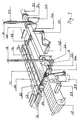
- the device used to load the products onto the plates comprises a pusher 14 constituted by a horizontal bar whose length is approximately equal to the useful width of the plates and which is coupled, by articulations, to two chains 16 which are wound on two sprockets 18 and are then guided in vertical sheaths shown schematically at 20.
- the length of the chains must be sufficient to allow the pusher to move over the entire length of the plates, which can exceed 3 m.
- the sheaths 20 must have a corresponding length and, to reduce their bulk, are bent forward and then downward, in the form of a hairpin.
- the pinions 18 are keyed onto a shaft 22 mounted on bearings 24 fixed to the chassis of the device.
- this chassis has not been shown nor, consequently, the means for fixing the bearings and the other members which are integral therewith; these means are conventional and their description is not necessary for understanding the invention.
- the shaft 22 can be rotated by a two-speed motor - reducer - brake group 26, mounted floating on one end of the shaft and comprising a torque recovery arm linked to the chassis of the device by a pneumatic cylinder 28.
- An encoder 30 mounted at the other end of the shaft 22 makes it possible to measure the number of turns and fractional turns made by the shaft 22 and, consequently, the displacements of the pusher 14.
- the chains 16 are formed of links 32 having abutment surfaces 34 which, when the links are aligned, are in contact with each other and allow the relative rotation of the links only in one direction, that allowing the winding the chains around the sprockets 18.
- the chains 16 are provided with rollers 36 mounted on the axes of articulations 38 of the links and with which the teeth of the pinions engage.
- the part of the sprockets on which the chain is wound is surrounded by a fixed ramp 40 in an arc of circle on which the rollers roll and which takes up the reactions of the chain (only one of these ramps has been shown in FIG. 1).
- the chains 16 also include sliding pads 42 which support the chains in the horizontal portion of their course. These pads are constituted by plastic plates with low coefficient of friction which are mounted on the articulation axes of the links on the two sides of the chain and whose height is greater than that of the links so that they keep them away from the surfaces on which they slide.
- rollers 36 and the pads 42 cooperate with a track and sliding surfaces, respectively, which guide the chains (FIG. 3).
- the chains are supported by rectilinear guides 44 on which the pads 42 slide.
- These guides are integral with a tube 46 rotatably mounted on the shaft 22 and the rotation of which can be controlled by a jack 48 coupled, by means of a rod and lever system, to an arm 50 fixed to the tube.
- the rotation of the tube and the guides makes it possible to lift the chains and the pusher to move them away from the plane of the conveyor 12. It is possible, thanks to this improvement, to bring products to be frozen to the loading position, by means of the conveyor 12 , during the return stroke of the pusher, which saves time and reduces the duration of the loading cycle.
- the pusher 14 is provided at its ends with rollers 52 which keep it at a short distance from the surfaces above which it moves, to eliminate friction.
- the freezer operates continuously and, in steady state, the plates are always loaded.
- the plates are always loaded.
- it is necessary simultaneously to discharge the frozen products which are there.
- frost the products frozen food sticks to the plates and it is necessary to peel them off before they can be unloaded by sliding them on the plate.
- This operation is carried out by means of the pusher 14 which is brought from its retracted position, below the conveyor 12, into contact with the first row of products located on the plate, then moved a few centimeters beyond this position.
- the position of the pusher 14 is determined by means of the encoder 30 which controls the reversal of the direction of rotation of the motor 26, when the pusher reaches the limit position, predetermined for this operation, and stops the motor when the pusher is again in its initial position.
- the effort required to take off the products is determined from a measurement of the pressure in the jack 28; if this pressure exceeds a predetermined value, the power supply to the motor 26 can be cut and an alarm triggered to warn the operator of an abnormal situation. Since it is easier to take off by applying shocks rather than a continuous push on frozen products, it may be advantageous to move the pusher in an alternating movement, by means of the jack 28, after the 'having brought into contact with the products by means of group 26.
- a solenoid valve with manual or automatic control allows this use of the jack 28.
- the conveyor 12 is stopped and not loaded. It can be started during the return race, as soon as the pusher is sufficiently retracted to allow the passage of a row of products.
- the conveyor 12 is supplied with products to be frozen by a conveyor located upstream.
- the stopping of the row 11 against the stop 54 controls the starting of the motor 26 which moves the pusher forward; the latter pushes row 11, sliding it onto the conveyor and then onto the sheet 13 until it comes into contact with the first row of frozen products 58 located on the plate.
- the advance of the pusher then causes the displacement of all the rows of frozen products on the plate and the expulsion of the last row through the unloading opening provided on the rear face of the cabin; this row falls on an evacuation conveyor placed at the rear of the freezer.
- the encoder 30 controls the reversal of the rotation of the motor 26, to return the pusher to its initial position, and the lifting of the chains and of the pusher, by means of the jack 48.
- the same operation sequence is then triggered to load another row of products on the plate, the chains and the pusher being returned to the low position after a time predetermined, less than the duration of the return stroke of the pusher.
- the number of rows that can be loaded on a plate is predetermined and the number of rows that have actually been loaded on the plate is counted at the barrier located between the conveyor 12 and the conveyor which feeds it; when this number is reached, the barrier remains closed and a new loading cycle does not begin until after a new plate has been brought to the level of the conveyor 12.
- the device which is the subject of the invention makes it possible to unload all the plates, before the freezer stops.
- the pusher is moved step by step over the entire length of the plates. It also makes it possible to clean the plates, after defrosting, by replacing the pusher with a scraper.
Abstract
Description
La présente invention concerne les surgélateurs à plaques constitués par une pile de plaques horizontales, creuses, dans lesquelles circule un fluide réfrigérant et qui sont placées à l'intérieur d'une cabine isolante comportant sur deux faces opposées des ouvertures pour le chargement des produits à surgeler et de déchargement des produits surgelés, des moyens pour déplacer verticalement la pile de plaques et amener l'une après l'autre chaque plaque au niveau desdites ouvertures, et des moyens pour charger les produits à surgeler sur la plaque se trouvant au niveau de ces ouvertures, à travers l'une d'elles, et pour décharger les produits surgelés à travers l'autre ouverture. Un tel surgélateur est décrit, par exemple, dans le document GB-A-2 053 831.The present invention relates to plate freezers consisting of a stack of horizontal, hollow plates, in which a cooling fluid circulates and which are placed inside an insulating cabin comprising on two opposite sides openings for loading the products to freezing and unloading frozen products, means for vertically moving the stack of plates and bringing each plate one after the other at said openings, and means for loading the products to be frozen onto the plate located at these openings, through one of them, and to discharge the frozen products through the other opening. Such a deep-freezer is described, for example, in the document GB-A-2,053,831.
Dans ces appareils, les produits à surgeler sont amenés devant l'ouverture de chargement par un transporteur à bande sans fin horizontal et sont chargés au moyen d'un poussoir. Les produits sont rangés côte-à-côte sur le transporteur, la longueur de la rangée étant égale à la largeur utile des plaques, et tous les produits de la rangée sont chargés en même temps sur la plaque. En régime permanent, le déchargement des produits surgelés et le chargement de produits à surgeler sont effectués simultanément, l'introductiond'une rangée de produits à surgeler provoquant la translation de l'ensemble des produits se trouvant sur la plaque vers l'ouverture de déchargement et l'expulsion à travers celle-ci de la rangée qui en est la plus proche.In these devices, the products to be frozen are brought to the loading opening by a horizontal endless belt conveyor and are loaded by means of a pusher. The products are stored side by side on the conveyor, the length of the row being equal to the useful width of the plates, and all the products in the row are loaded at the same time on the plate. In continuous operation, the unloading of frozen products and the loading of products to be frozen are carried out simultaneously, the introduction of a row of products to be frozen causing the translation of all the products on the plate towards the unloading opening and expulsion to across it from the row closest to it.
Pour le chargement et le déchargement rangée par rangée des produits, la course du poussoir peut être relativement faible. Mais généralement le poussoir est également utilisé pour vider complètement le surgélateur avant arrêt, par exemple pour le dégivrer; la course du poussoir doit alors être supérieure à la longueur des plaques (3 à 4 m). Il n'est donc pas possible d'utiliser des vérins classiques pour actionner le poussoir et on utilise généralement des chaînes spéciales qui ne peuvent se courber que dans un sens, à partir de leur position rectiligne, de sorte qu'elles sont capables d'exercer non seulement des efforts de traction mais aussi des efforts de poussée, sous certaines conditions d'application des efforts. Ces chaînes sont mues, comme des crémaillères, par des pignons qui engrènent avec leur partie rectiligne et horizontale dont l'extrémité est attelée au poussoir. A l'arrière des pignons, les chaînes sont guidées dans des gaines courbées vers le haut pour réduire l'encombrement. Les pignons n'étant en prise avec les chaînes que par une dent ou deux, les efforts qui peuvent être transmis au poussoir sont limités. Or, il est parfois nécessaire d'exercer des efforts importants pour décoller les produits surgelés de la plaque, avant un nouveau chargement, et cela peut s'avérer impossible avec les dispositifs connus.When loading and unloading row by row of products, the stroke of the pusher can be relatively short. But generally the pusher is also used to completely empty the freezer before stopping, for example to defrost it; the stroke of the pusher must then be greater than the length of the plates (3 to 4 m). It is therefore not possible to use conventional jacks to actuate the pusher and special chains are generally used which can only bend in one direction, from their rectilinear position, so that they are capable of exert not only tensile forces but also pushing forces, under certain conditions of application of the forces. These chains are moved, like racks, by pinions which mesh with their rectilinear and horizontal part whose end is coupled to the pusher. At the rear of the sprockets, the chains are guided in upwardly curved sheaths to reduce bulk. Since the sprockets are only engaged with the chains by a tooth or two, the forces which can be transmitted to the pusher are limited. However, it is sometimes necessary to exert significant efforts to remove the frozen products from the plate, before a new loading, and this may prove to be impossible with known devices.
Le but de la présente invention est de remédier à cet inconvénient et de fournir un dispositif capable d'exercer un effort important sur le poussoir sans avoir à surdimensionner les organes du dispositif et permettant de contrôler cet effort et, si nécessaire, de le limiter à une valeur acceptable.The object of the present invention is to remedy this drawback and to provide a device capable of exerting a significant force on the pusher without having to oversize the organs of the device and making it possible to control this effort and, if necessary, to limit it to an acceptable value.
Le dispositif objet de la présente invention est caractérisé en ce que les chaînes ont des maillons courts de façon à pouvoir s'enrouler autour des pignons et sont en prise avec ceux-ci sur un quart de cercle environ, et en ce que les pignons sont fixés sur un arbre qui est entrainé en rotation par un groupe moto-réducteur-frein monté flottant sur ledit arbre et comportant un bras de reprise du couple relié au châssis du surgélateur par un dynamomètre. Le dynamomètre sera avantageusement constitué par un vérin pneumatique et des moyens de mesure de la pression dans le vérin seront prévus pour déterminer le couple du moteur et, par conséquent, l'effort exercé par le poussoir. Des moyens de commande dudit vérin pourront aussi être prévus pour provoquer la rotation de l'arbre, le frein dudit groupe étant serré, et, par conséquent, l'avance du poussoir sur une courte distance.The device which is the subject of the present invention is characterized in that the chains have short links so that they can be wound around the pinions and are engaged therewith over a quarter of a circle approximately, and in that the pinions are fixed on a shaft which is rotated by a gear motor-brake unit mounted floating on said shaft and comprising a torque recovery arm connected to the chassis of the freezer by a dynamometer. The dynamometer will advantageously be constituted by a pneumatic cylinder and means for measuring the pressure in the cylinder will be provided to determine the torque of the motor and, consequently, the force exerted by the pusher. Control means of said jack may also be provided to cause the rotation of the shaft, the brake of said group being applied, and, consequently, the advance of the pusher over a short distance.
Suivant une forme préférentielle de l'invention, les chaînes sont soutenues par des guides, dans la portion de leur trajet entre les pignons et le transporteur de chargement, ces guides sont montés rotatifs autour de l'axe des pignons, et des moyens sont prévus pour faire tourner ces guides autour dudit axe et soulever les chaînes et le poussoir. Ces guides peuvent, par exemple, être fixés sur un tube coaxial à l'arbre des pignons et dont la rotation, par rapport à l'arbre, peut être commandée par un vérin attelé à un bras solidaire dudit tube. Ce perfectionnement permet d'amener une nouvelle rangée de produits à surgeler devant l'ouverture de chargement, au moyen du transporteur, avant que le poussoir ne soit complètement rétracté, en faisant passer ce dernier au-dessus des produits se trouvant sur le transporteur.According to a preferred form of the invention, the chains are supported by guides, in the portion of their path between the pinions and the loading conveyor, these guides are mounted to rotate around the axis of the pinions, and means are provided. to rotate these guides around said axis and lift the chains and the pusher. These guides can, for example, be fixed on a tube coaxial with the pinion shaft and the rotation of which, relative to the shaft, can be controlled by a jack coupled to an arm integral with said tube. This improvement makes it possible to bring a new row of products to be frozen in front of the loading opening, by means of the conveyor, before the pusher is completely retracted, by passing the latter over the products located on the conveyor.
D'autres caractéristiques de l'invention apparaîtront à la lecture de la description qui suit et se réfère aux dessins l'accompagnant qui montrent, à titre d'exemple non-limitatif, une forme de réalisation de l'invention. Sur ces dessins :
- La figure 1 est une vue en perspective d'un dispositif de chargement et déchargement d'un surgélateur à plaques réalisé conformément à l'invention;
- La figure 2 est une vue en élévation d'une partie de l'une des chaînes et d'un des pignons actionnant le poussoir du dispositif de la figure 1, et
- La figure 3 est une coupe transversale de la chaîne et de sa gaine de guidage.
Sur la figure 1 du dessin seulement deux
- FIG. 1 is a perspective view of a device for loading and unloading a plate freezer produced in accordance with the invention;
- FIG. 2 is an elevation view of part of one of the chains and of one of the pinions actuating the pusher of the device of FIG. 1, and
- Figure 3 is a cross section of the chain and its guide sheath.
In Figure 1 of the drawing only two
Le dispositif servant à charger les produits sur les plaques comprend un poussoir 14 constitué par une barre horizontale dont la longueur est approximativement égale à la largeur utile des plaques et qui est attelée, par des articulations, à deux chaînes 16 qui s'enroulent sur deux pignons 18 et sont ensuite guidées dans des gaines verticales représentées schématiquement en 20. La longueur des chaînes doit être suffisante pour permettre au poussoir de se déplacer sur toute la longueur des plaques, qui peut dépasser 3 m. Les gaines 20 doivent avoir une longueur correspondante et, pour diminuer leur encombrement, sont recourbées vers l'avant puis vers le bas, en forme d'épingle à cheveux.The device used to load the products onto the plates comprises a
Les pignons 18 sont clavetés sur un arbre 22 monté sur des paliers 24 fixés sur le châssis de l'appareil. Pour ne pas compliquer le dessin, ce châssis n'a pas été représenté ni, par conséquent, les moyens de fixation des paliers et des autres organes qui en sont solidaires; ces moyens sont classiques et leur description n'est pas nécessaire à la compréhension de l'invention.The
L'arbre 22 peut être entraîné en rotation par un groupe moteur - réducteur - frein 26 à deux vitesses, monté flottant sur une extrémité de l'arbre et comportant un bras de reprise de couple lié au châssis de l'appareil par un vérin pneumatique 28. Un codeur 30 monté à l'autre extrémité de l'arbre 22 permet de mesurer le nombre de tours et de fractions de tour effectués par l'arbre 22 et, par conséquent, les déplacements du poussoir 14.The
Les chaînes 16 sont formées de maillons 32 comportant des surfaces de butée 34 qui, lorsque les maillons sont alignés, sont en contact l'une avec l'autre et n'autorisent la rotation relative des maillons que dans un sens, celui permettant l'enroulement des chaînes autour des pignons 18.The
Les chaînes 16 sont munies de galets 36 montés sur les axes d'articulations 38 des maillons et avec lesquels les dents des pignons viennent en prise. La partie des pignons sur laquelle s'enroule la chaîne est entourée par une rampe fixe 40 en arc de cercle sur laquelle roulent les galets et qui reprend les réactions de la chaîne (une seule de ces rampes a été représentée sur la figure 1).The
Les chaînes 16 comportant également des patins de glissement 42 qui supportent les chaînes dans la portion horizontale de leur parcours. Ces patins sont constitués par des plaquettes en matière plastique à faible coefficient de frottement qui sont montées sur les axes d'articulation des maillons sur les deux côtés de la chaînes et dont la hauteur est supérieure à celle des maillons de telle sorte qu'elles maintiennent ces derniers à l'écart des surfaces sur lesquelles elles glissent.The
A l'intérieur des gaines 20, les galets 36 et les patins 42 coopèrent avec une voie de roulement et des surfaces de glissement, respectivement, qui assurent le guidage des chaînes (figure 3).Inside the
Entre les pignons 18 et le transporteur 12, les chaînes sont soutenues par des guides rectilignes 44 sur lesquels glissent les patins 42. Ces guides sont solidaires d'un tube 46 monté rotatif sur l'arbre 22 et dont la rotation peut être commandée par un vérin 48 attelé, par l'intermédiaire d'un système à bielles et levier, à un bras 50 fixé sur le tube. La rotation du tube et des guides permet de soulever les chaînes et le poussoir pour les écarter du plan du transporteur 12. Il est possible, grâce à ce perfectionnement, d'amener des produits à surgeler en position de chargement, au moyen du transporteur 12, pendant la course retour du poussoir, ce qui permet de gagner du temps et de réduire la durée du cycle de chargement.Between the
Le poussoir 14 est muni à ses extrémités de galets 52 qui le maintiennent à faible distance des surfaces au-dessus desquelles il se déplace, pour éliminer les frottements.The
Le fonctionnement du surgélateur est continu et, en régime permanent, les plaques sont toujours chargées. Lorsqu'on charge les produits à surgeler sur une plaque, il faut simultanément décharger les produits surgelés qui s'y trouvent. Par suite de la formation de givre, les produits surgelés adhèrent aux plaques et il est nécessaire de les décoller avant de pouvoir les décharger en les faisant glisser sur la plaque. Cette opération est effectuée au moyen du poussoir 14 qui est amené de sa position rétractée, en deça du transporteur 12, au contact de la premère rangée de produits se trouvant sur la plaque, puis déplacé de quelques centimètres au-delà de cette position.The freezer operates continuously and, in steady state, the plates are always loaded. When loading the products to be frozen on a plate, it is necessary simultaneously to discharge the frozen products which are there. As a result of the formation of frost, the products frozen food sticks to the plates and it is necessary to peel them off before they can be unloaded by sliding them on the plate. This operation is carried out by means of the
La position du poussoir 14 est déterminée au moyen du codeur 30 qui commande l'inversion du sens de rotation du moteur 26, lorsque le poussoir atteint la position limite, prédéterminée pour cette opération, et arrête le moteur quand le poussoir se trouve à nouveau dans sa position initiale. L'effort nécessaire pour décoller les produits est déterminé à partir d'une mesure de la pression dans le vérin 28; si cette pression excède une valeur prédéterminée, l'alimentation du moteur 26 peut être coupée et une alarme déclenchée pour prévenir l'opérateur d'une situation anormale. Etant donné qu'il est plus facile d'effectuer le décollement en exerçant des chocs plutôt qu'une poussée continue sur les produits surgelés, il pourra être avantageux de déplacer le poussoir d'un mouvement alternatif, au moyen du vérin 28, après l'avoir amené au contact des produits au moyen du groupe 26. Une électro-vanne à commande manuelle ou automatique permet cette utilisation du vérin 28. Pendant la course aller du poussoir, le transporteur 12 est à l'arrêt et non chargé. Il peut être mis en route pendant la course retour, dès que le poussoir est suffisamment rétracté pour permettre le passage d'une rangée de produits.The position of the
Le transporteur 12 est alimenté en produits à surgeler par un transporteur situé en amont. Une barrière éclipsable placée entre les deux transporteurs, une cellule photo-électrique située en aval, à une distance de la barrière égale à longueur de la plus grande rangée des produits à surgeler pouvant être chargée sur les plaques,et une butée 54 placée sur le transporteur, en aval de la cellule, permettent d'isoler de l'amont une rangée 11 de produits et l'amener en face de la plaque sur laquelle elle doit être chargée. L'arrêt de la rangée 11 contre la butée 54 commande la mise en route du moteur 26 qui déplace le poussoir vers l'avant; celui-ci pousse la rangée 11, en la faisant glisser sur le transporteur puis sur la tôle 13 jusqu'à ce qu'elle vienne au contact de la première rangée de produits surgelés 58 se trouvant sur la plaque. L'avance du poussoir provoque alors le déplacement de toute les rangées de produits surgelés se trouvant sur la plaque et l'expulsion de la dernière rangée à travers l'ouverture de déchargement prévue sur la face arrière de la cabine; cette rangée tombe sur un transporteur d'évacuation placé à l'arrière du surgélateur. Dès que la rangée 11 est chargée sur la plaque, le codeur 30 commande l'inversion de la rotation du moteur 26, pour ramener le poussoir à sa position initiale, et le relevage des chaînes et du poussoir, au moyen du vérin 48. La même suite d'opération est alors déclenchée pour charger une autre rangée de produits sur la plaque, les chaînes et le poussoir étant ramenés en position basse au bout d'un temps prédéterminé, inférieur à la durée de la course retour du poussoir.The
Le nombre de rangées que l'on peut charger sur une plaque est prédéterminée et le nombre de rangées qui ont été effectivement chargées sur la plaque est compté au niveau de la barrière située entre le transporteur 12 et le transporteur qui l'alimente; lorsque ce nombre est atteint, la barrière reste fermée et un nouveau cycle de chargement ne commence qu'après qu'une nouvelle plaque ait été amenée au niveau du transporteur 12.The number of rows that can be loaded on a plate is predetermined and the number of rows that have actually been loaded on the plate is counted at the barrier located between the
Outre les fonctions décrites ci-dessus, le dispositif objet de l'invention permet de décharger toutes les plaques, avant l'arrêt du surgélateur. Dans ce cas, le poussoir est déplacé pas-à-pas sur toute la longueur des plaques. Il permet également de nettoyer les plaques, après dégivrage, en remplaçant le poussoir par un râcleur.In addition to the functions described above, the device which is the subject of the invention makes it possible to unload all the plates, before the freezer stops. In this case, the pusher is moved step by step over the entire length of the plates. It also makes it possible to clean the plates, after defrosting, by replacing the pusher with a scraper.
Claims (6)
- Plate freezer loading device comprising a conveyor (12) enabling to place the products to be frozen (11) in front of the plates (10) and at the level of the same, and a pusher (14) permitting to transfer the products in a translatory movement from the conveyor onto the plates, the said pusher being coupled to pushing chains (16) in mesh with drive pinions (18), characterized in that the chains (16) have short links so as to be able to wrap around the pinions (18) and are in mesh with the latter over approximately a quarter circle, and in that the pinions (18) are fixed to a shaft (22) which can be rotated by a motor - reducer - brake set (26) floatingly mounted on the said shaft and comprising a torque arm connected to the freezer framework by a dynamometer (28).
- Device according to claim 1, characterized in that the said dynamometer is constituted by a pneumatic cylinder (28) and means for measuring the pressure in the cylinder.
- Device according to claim 2, characterized in that it comprises means for controlling the alternating movements of the said cylinder.
- Device according to claim 1, 2 or 3, characterized in that the said chains are provided with slide shoes (42) which support the chains (16) along the horizontal part of their travel and which are constituted by small plates made of a low friction-coefficient material and mounted on the chain link pins so as to maintain the said links apart from the surface on which they glide.
- Device according to claims 1, 2, 3 or 4, characterized in that the chains (16) are supported by guides (44) in that portion of their travel situated between the pinions (18) and the conveyor (12), in that these guides are mounted rotatively around the axis of the pinions (18), and in that means (48, 50) are provided for rotating these guides about the said axis and for lifting the chains (16) and the pusher (14).
- Device according to claim 5, characterized in that the said guides (44) are integral with a tube (46) coaxial with the shaft (22) which bears the said pinions (18), and a cylinder (48) coupled to an arm (50) integral with the said tube permits to rotate the latter in relation to the shaft.
Applications Claiming Priority (2)
| Application Number | Priority Date | Filing Date | Title |
|---|---|---|---|
| FR8906641A FR2647195B1 (en) | 1989-05-22 | 1989-05-22 | LOADING AND UNLOADING DEVICE FOR PLATE FREEZER |
| FR8906641 | 1989-05-22 |
Publications (2)
| Publication Number | Publication Date |
|---|---|
| EP0399883A1 EP0399883A1 (en) | 1990-11-28 |
| EP0399883B1 true EP0399883B1 (en) | 1992-12-02 |
Family
ID=9381863
Family Applications (1)
| Application Number | Title | Priority Date | Filing Date |
|---|---|---|---|
| EP90401334A Expired - Lifetime EP0399883B1 (en) | 1989-05-22 | 1990-05-18 | Plate freezer loading and unloading device |
Country Status (9)
| Country | Link |
|---|---|
| US (1) | US5038916A (en) |
| EP (1) | EP0399883B1 (en) |
| JP (1) | JPH0827121B2 (en) |
| AT (1) | ATE83065T1 (en) |
| DE (1) | DE69000518T2 (en) |
| DK (1) | DK0399883T3 (en) |
| ES (1) | ES2035721T3 (en) |
| FR (1) | FR2647195B1 (en) |
| RU (1) | RU2040743C1 (en) |
Families Citing this family (10)
| Publication number | Priority date | Publication date | Assignee | Title |
|---|---|---|---|---|
| US5489016A (en) * | 1994-11-29 | 1996-02-06 | Technical Industrial Development Enterprises, Inc. | Pusher bar apparatus to remove containers from a splice plate between conveyors |
| US7089717B2 (en) * | 2003-05-05 | 2006-08-15 | Langen Packaging Inc. | Tray loader |
| GB0413115D0 (en) * | 2004-06-11 | 2004-07-14 | Boc Group Plc | Freeze dryer |
| CN101329133B (en) * | 2008-06-20 | 2010-06-09 | 南通冷冻设备有限公司 | Automatic discharge vertical flat plate freezing apparatus |
| EP2702341B1 (en) | 2011-04-28 | 2018-09-26 | Skaginn HF. | Automatic, periodic plate-freezing |
| CN104890961B (en) * | 2015-04-21 | 2017-04-12 | 青岛环速科技有限公司 | Automatic food cooling production line |
| EP3294651A4 (en) * | 2015-05-11 | 2019-01-09 | Gebo Cermex Canada Inc. | Vertical accumulation in a treatment line |
| NO343196B1 (en) * | 2016-04-20 | 2018-11-26 | Optimar As | Apparatus for filling and emptying horizontal freezers and freezing system comprising one or more apparatus for emptying and filling horizontal freezers. |
| CN106642933B (en) * | 2016-12-05 | 2019-01-15 | 泾县麦蓝网络技术服务有限公司 | A kind of Intelligent bracelet batch cooling device |
| JP6804337B2 (en) * | 2017-03-01 | 2020-12-23 | 東洋自動機株式会社 | Relay device |
Family Cites Families (19)
| Publication number | Priority date | Publication date | Assignee | Title |
|---|---|---|---|---|
| US1680441A (en) * | 1924-02-15 | 1928-08-14 | Mathews Gravity Carrier Compan | Tray for bread-cooling machines |
| US1906605A (en) * | 1931-03-07 | 1933-05-02 | Owens Illinois Glass Co | Leer feeder |
| FR981511A (en) * | 1943-04-28 | 1951-05-28 | Continuous thin-layer freezer | |
| US2736417A (en) * | 1951-04-13 | 1956-02-28 | Greer J W Co | Tray conveyor mechanism |
| US2808921A (en) * | 1954-06-09 | 1957-10-08 | Frank W Knowles | Package feeder |
| US2842253A (en) * | 1957-08-28 | 1958-07-08 | Amerio Refrigerating Equipment | Conveyor system |
| US2929491A (en) * | 1957-09-30 | 1960-03-22 | Pfizer & Co C | Article storage and feeding device |
| US3198309A (en) * | 1963-02-14 | 1965-08-03 | Baker Perkins Inc | Transfer apparatus |
| US3244266A (en) * | 1965-02-24 | 1966-04-05 | Anthony T Zappia | Lehr loader |
| US3557975A (en) * | 1969-03-13 | 1971-01-26 | St Regis Paper Co | Pusher assembly for freezers |
| BE790059A (en) * | 1971-10-13 | 1973-04-13 | Maul Bros Inc | GLASS CONTAINER HANDLING EQUIPMENT |
| GB1359211A (en) * | 1972-01-27 | 1974-07-10 | Jackstone Froster Ltd | Freezing apparatus |
| US3774754A (en) * | 1972-05-22 | 1973-11-27 | J Hedlund | Material handling apparatus |
| US4003464A (en) * | 1975-04-01 | 1977-01-18 | Ball Brothers Service Corporation | Double arm push bar stacker |
| US4253560A (en) * | 1979-06-04 | 1981-03-03 | Fmc Corporation | Transfer conveyor for frozen confections |
| FR2461905A1 (en) * | 1979-07-23 | 1981-02-06 | Samifi Babcock Samifi Internal | DEVICE FOR INTRODUCING AND ADVANCING PRODUCTS ON PLATES IN A FREEZER WITH HORIZONTAL PLATES |
| IT1152323B (en) * | 1982-08-04 | 1986-12-31 | Babcock Samifi Spa | DEVICE FOR THE STORAGE AND AUTOMATIC COLLECTION OF ELEMENTS KNOWN AS INTERMEDIATE, SUITABLE FOR LOADING, ADVANCING AND UNLOADING OF CERTAIN PRODUCTS, FROM A HORIZONTAL PLATE FREEZER |
| IT1175652B (en) * | 1984-08-29 | 1987-07-15 | Elica Spa | WASHING MACHINE FOR CLOTHS WITH ROTATION OF WATER JETS WITHOUT BASKET IN MOVEMENT |
| US4663485A (en) * | 1986-07-22 | 1987-05-05 | Celanese Corporation | Process for purifying 4-hydroxyacetophenone |
-
1989
- 1989-05-22 FR FR8906641A patent/FR2647195B1/en not_active Expired - Fee Related
-
1990
- 1990-05-11 US US07/522,536 patent/US5038916A/en not_active Expired - Fee Related
- 1990-05-18 DK DK90401334.9T patent/DK0399883T3/en active
- 1990-05-18 AT AT90401334T patent/ATE83065T1/en not_active IP Right Cessation
- 1990-05-18 DE DE9090401334T patent/DE69000518T2/en not_active Expired - Fee Related
- 1990-05-18 ES ES199090401334T patent/ES2035721T3/en not_active Expired - Lifetime
- 1990-05-18 EP EP90401334A patent/EP0399883B1/en not_active Expired - Lifetime
- 1990-05-21 RU SU904743907A patent/RU2040743C1/en active
- 1990-05-21 JP JP2129355A patent/JPH0827121B2/en not_active Expired - Lifetime
Also Published As
| Publication number | Publication date |
|---|---|
| US5038916A (en) | 1991-08-13 |
| FR2647195B1 (en) | 1994-06-03 |
| ATE83065T1 (en) | 1992-12-15 |
| FR2647195A1 (en) | 1990-11-23 |
| EP0399883A1 (en) | 1990-11-28 |
| RU2040743C1 (en) | 1995-07-25 |
| DE69000518T2 (en) | 1993-04-22 |
| DK0399883T3 (en) | 1993-03-29 |
| JPH0827121B2 (en) | 1996-03-21 |
| ES2035721T3 (en) | 1993-04-16 |
| DE69000518D1 (en) | 1993-01-14 |
| JPH03117873A (en) | 1991-05-20 |
Similar Documents
| Publication | Publication Date | Title |
|---|---|---|
| EP0399883B1 (en) | Plate freezer loading and unloading device | |
| EP2176147B1 (en) | Device for forming batches of substantially parallelepiped objects moving on a conveyor belt | |
| EP3283857B1 (en) | Device for transporting objects and conveying and weighing device provided with such transporting devices | |
| FR2482830A1 (en) | ENVELOPE FEEDING MECHANISM OF A SAUSAGE FILLING MACHINE | |
| CH670807A5 (en) | ||
| EP0638496A1 (en) | Method and means for introducing sheet-like material in a machine | |
| EP0543711B1 (en) | Bridge element, especially for surmounting gaps by vehicles | |
| FR2605909A1 (en) | METAL WIRE INSTALLATION | |
| CA2366847C (en) | Process and device for in-line storage of packages of flat products such as diapers or sanitary napkins | |
| FR2500266A1 (en) | Mechanised elongation of dough pieces for French stick loaves - eliminating manual working of dough between dividing and final proving | |
| FR2478580A1 (en) | FIXING MACHINE | |
| FR2642269A1 (en) | Device for installing and immobilising animals to be milked | |
| FR2918653A1 (en) | Freeze-drying treating cabinet/tank plate unloading device for pharmaceutical field, has push bar selectively activated and having sweeping traversal area sweeping plate to reach base zone of plate upto inlet boundary of collection surface | |
| FR2618132A1 (en) | Installation and method for placing elongate products, such as sausages or products of similar shape, on refrigerator shelves (wire trays) | |
| FR2611650A1 (en) | DEVICE FOR TIETING A FLEXIBLE LINK | |
| EP0993769A1 (en) | Curved path scraping device for waste removal | |
| FR2623472A1 (en) | Chain for automatic palletisation of stacked packages | |
| WO2018002518A1 (en) | Device for transferring products by sweeping | |
| FR2617145A1 (en) | Magazine for storing and dispensing objects | |
| EP0629565A1 (en) | Telescopic table with roller conveyor | |
| FR2829477A1 (en) | Automatic device for continuous emptying of crates into hopper | |
| CH453190A (en) | Installation for the storage of pasta prior to packaging | |
| FR2549409A1 (en) | Device for cutting out flat pieces from flexible material, particularly a machine for cutting out slices of bacon and removing rind | |
| FR2575732A1 (en) | DISTRIBUTOR FOR ORDERING OBJECTS, IN PARTICULAR AGRICULTURAL PRODUCTS, DISTRIBUTION METHOD AND INSTALLATIONS COMPRISING SUCH A DISTRIBUTOR | |
| EP0089915A1 (en) | Plant for binding wire coils |
Legal Events
| Date | Code | Title | Description |
|---|---|---|---|
| PUAI | Public reference made under article 153(3) epc to a published international application that has entered the european phase |
Free format text: ORIGINAL CODE: 0009012 |
|
| AK | Designated contracting states |
Kind code of ref document: A1 Designated state(s): AT BE CH DE DK ES GB IT LI LU NL SE |
|
| 17P | Request for examination filed |
Effective date: 19901222 |
|
| 17Q | First examination report despatched |
Effective date: 19920204 |
|
| GRAA | (expected) grant |
Free format text: ORIGINAL CODE: 0009210 |
|
| ITF | It: translation for a ep patent filed |
Owner name: BARZANO' E ZANARDO MILA |
|
| AK | Designated contracting states |
Kind code of ref document: B1 Designated state(s): AT BE CH DE DK ES GB IT LI LU NL SE |
|
| REF | Corresponds to: |
Ref document number: 83065 Country of ref document: AT Date of ref document: 19921215 Kind code of ref document: T |
|
| GBT | Gb: translation of ep patent filed (gb section 77(6)(a)/1977) |
Effective date: 19921211 |
|
| REF | Corresponds to: |
Ref document number: 69000518 Country of ref document: DE Date of ref document: 19930114 |
|
| REG | Reference to a national code |
Ref country code: DK Ref legal event code: T3 |
|
| PGFP | Annual fee paid to national office [announced via postgrant information from national office to epo] |
Ref country code: DK Payment date: 19930401 Year of fee payment: 4 |
|
| REG | Reference to a national code |
Ref country code: ES Ref legal event code: FG2A Ref document number: 2035721 Country of ref document: ES Kind code of ref document: T3 |
|
| PGFP | Annual fee paid to national office [announced via postgrant information from national office to epo] |
Ref country code: CH Payment date: 19930506 Year of fee payment: 4 |
|
| PGFP | Annual fee paid to national office [announced via postgrant information from national office to epo] |
Ref country code: AT Payment date: 19930526 Year of fee payment: 4 |
|
| PGFP | Annual fee paid to national office [announced via postgrant information from national office to epo] |
Ref country code: NL Payment date: 19930531 Year of fee payment: 4 |
|
| PGFP | Annual fee paid to national office [announced via postgrant information from national office to epo] |
Ref country code: DE Payment date: 19930730 Year of fee payment: 4 |
|
| PLBE | No opposition filed within time limit |
Free format text: ORIGINAL CODE: 0009261 |
|
| STAA | Information on the status of an ep patent application or granted ep patent |
Free format text: STATUS: NO OPPOSITION FILED WITHIN TIME LIMIT |
|
| 26N | No opposition filed | ||
| PGFP | Annual fee paid to national office [announced via postgrant information from national office to epo] |
Ref country code: BE Payment date: 19940428 Year of fee payment: 5 |
|
| PGFP | Annual fee paid to national office [announced via postgrant information from national office to epo] |
Ref country code: ES Payment date: 19940429 Year of fee payment: 5 |
|
| PGFP | Annual fee paid to national office [announced via postgrant information from national office to epo] |
Ref country code: LU Payment date: 19940430 Year of fee payment: 5 |
|
| PGFP | Annual fee paid to national office [announced via postgrant information from national office to epo] |
Ref country code: SE Payment date: 19940509 Year of fee payment: 5 |
|
| PGFP | Annual fee paid to national office [announced via postgrant information from national office to epo] |
Ref country code: GB Payment date: 19940511 Year of fee payment: 5 |
|
| PG25 | Lapsed in a contracting state [announced via postgrant information from national office to epo] |
Ref country code: DK Effective date: 19940518 Ref country code: AT Effective date: 19940518 |
|
| REG | Reference to a national code |
Ref country code: DK Ref legal event code: EBP |
|
| PG25 | Lapsed in a contracting state [announced via postgrant information from national office to epo] |
Ref country code: LI Effective date: 19940531 Ref country code: CH Effective date: 19940531 |
|
| EPTA | Lu: last paid annual fee | ||
| PG25 | Lapsed in a contracting state [announced via postgrant information from national office to epo] |
Ref country code: NL Effective date: 19941201 |
|
| NLV4 | Nl: lapsed or anulled due to non-payment of the annual fee | ||
| EAL | Se: european patent in force in sweden |
Ref document number: 90401334.9 |
|
| REG | Reference to a national code |
Ref country code: CH Ref legal event code: PL |
|
| PG25 | Lapsed in a contracting state [announced via postgrant information from national office to epo] |
Ref country code: DE Effective date: 19950201 |
|
| PG25 | Lapsed in a contracting state [announced via postgrant information from national office to epo] |
Ref country code: LU Free format text: LAPSE BECAUSE OF NON-PAYMENT OF DUE FEES Effective date: 19950518 Ref country code: GB Effective date: 19950518 |
|
| PG25 | Lapsed in a contracting state [announced via postgrant information from national office to epo] |
Ref country code: SE Effective date: 19950519 Ref country code: ES Free format text: LAPSE BECAUSE OF NON-PAYMENT OF DUE FEES Effective date: 19950519 |
|
| PG25 | Lapsed in a contracting state [announced via postgrant information from national office to epo] |
Ref country code: BE Effective date: 19950531 |
|
| BERE | Be: lapsed |
Owner name: S.A. PIERRE GUERIN Effective date: 19950531 |
|
| GBPC | Gb: european patent ceased through non-payment of renewal fee |
Effective date: 19950518 |
|
| EUG | Se: european patent has lapsed |
Ref document number: 90401334.9 |
|
| REG | Reference to a national code |
Ref country code: ES Ref legal event code: FD2A Effective date: 19990405 |
|
| PG25 | Lapsed in a contracting state [announced via postgrant information from national office to epo] |
Ref country code: IT Free format text: LAPSE BECAUSE OF NON-PAYMENT OF DUE FEES;WARNING: LAPSES OF ITALIAN PATENTS WITH EFFECTIVE DATE BEFORE 2007 MAY HAVE OCCURRED AT ANY TIME BEFORE 2007. THE CORRECT EFFECTIVE DATE MAY BE DIFFERENT FROM THE ONE RECORDED. Effective date: 20050518 |