EP0399166A1 - Vehicle roof with wind deflector - Google Patents
Vehicle roof with wind deflector Download PDFInfo
- Publication number
- EP0399166A1 EP0399166A1 EP90105529A EP90105529A EP0399166A1 EP 0399166 A1 EP0399166 A1 EP 0399166A1 EP 90105529 A EP90105529 A EP 90105529A EP 90105529 A EP90105529 A EP 90105529A EP 0399166 A1 EP0399166 A1 EP 0399166A1
- Authority
- EP
- European Patent Office
- Prior art keywords
- roof
- wind deflector
- cover
- vehicle
- longitudinal direction
- Prior art date
- Legal status (The legal status is an assumption and is not a legal conclusion. Google has not performed a legal analysis and makes no representation as to the accuracy of the status listed.)
- Withdrawn
Links
Images


Classifications
-
- B—PERFORMING OPERATIONS; TRANSPORTING
- B60—VEHICLES IN GENERAL
- B60J—WINDOWS, WINDSCREENS, NON-FIXED ROOFS, DOORS, OR SIMILAR DEVICES FOR VEHICLES; REMOVABLE EXTERNAL PROTECTIVE COVERINGS SPECIALLY ADAPTED FOR VEHICLES
- B60J7/00—Non-fixed roofs; Roofs with movable panels, e.g. rotary sunroofs
- B60J7/22—Wind deflectors for open roofs
Definitions
- the invention relates to a vehicle roof with a roof cutout formed in the solid roof skin, which can be optionally closed or at least partially exposed by means of a cover which can be adjusted in the longitudinal direction of the vehicle, and with a wind deflector which has a wind deflector blade which is between an exposed position and an inoperative position is pivotally mounted about a pivot axis running transversely to the longitudinal direction of the vehicle, which in turn can be adjusted along a guide in the longitudinal direction of the vehicle, the wind deflector pivoted into the non-operating position being able to be pushed into a receiving space located under the fixed roof skin in front of the front edge of the roof cutout.
- Wind deflector arrangements are also known in which a wind deflector plate is mounted in the region of the front edge of a roof cutout which can be closed by means of a cover and which is automatically adjusted between a working position and an inoperative position depending on the adjustment movement of the cover.
- a wind deflector plate is mounted in the region of the front edge of a roof cutout which can be closed by means of a cover and which is automatically adjusted between a working position and an inoperative position depending on the adjustment movement of the cover.
- the wind deflector blade is resiliently pre-tensioned in relation to the opening arms and the opening arms in relation to the roof frame in the direction of the working position.
- the wind deflector blade has a cam on the free edge away from the extension arms, which is supported on a roof-mounted cam track. If the cover is brought into the closed position, it pivots the extension arms so that they tilt the wind deflector blade backwards and at least partially push it forward under the part of the fixed roof surface that delimits the front edge of the roof opening, the cam sliding along the cam track.
- a cross-sectionally S-shaped wind deflector blade which is resiliently biased into an exposed position is pivotally mounted about a roof-fixed axis which is arranged in front of the roof cutout below the fixed roof skin.
- a push rod is articulated on the wind deflector blade, which cooperates with a driver on a front cover bearing in order to fold the wind deflector blade about its roof-fixed axis into the inoperative position when the cover approaches its closed position. It is also known in a sliding roof (DE-OS 25 05 736) to pivotally deflect a wind deflector blade on a holder which is pivotable about a roof-fixed axis lying in front of the front edge of the roof cutout and in turn is articulated with pivot levers.
- pivot levers are also pivotally mounted about non-rotatable axes, and they interact with sliding shoes on the sliding cover in order to lower the pivot axis connecting the wind deflector blade to the holder and close to the front edge of the roof cutout when the cover moves into its closed position.
- a sealing bead sitting on the front edge of the lid hits the wind deflector blade and swivels it against spring force with reference to the lowered holder until the wind deflector blade disappears under the fixed roof surface.
- These known wind deflector arrangements have in common that their applicability is limited to certain roof types, such as sunroofs, sunroofs and spoiler roofs.
- the known wind deflector arrangements are not suitable for fan roofs (compare patent application P 38 07 961.5), ie for roofs with a cover, the front edge of which can be lowered by pivoting the cover from a closed position into a fan position, in which a ventilation gap between the front edge of the cover and the front edge of the roof cutout, which can be closed by means of the cover, because in such a case the wind deflector would block or at least severely obstruct the passage of air through the ventilation gap.
- the invention specified in claim 1 has for its object to provide an easy-to-operate vehicle roof with wind deflector, which is not limited to special roof types, but is generally suitable for any type of roof and especially for training as a fan roof.
- this object is achieved in that a driver device for automatically driving the pivot axis of the wind deflector blade in the vehicle longitudinal direction is provided during part of the adjustment movement of the cover in the vehicle longitudinal direction.
- the pivot axis of the wind deflector blade is automatically adjusted in the longitudinal direction of the vehicle as a function of the adjustment movement of the cover.
- the wind deflector can easily be moved to a position in which it has roof functions, e.g. ventilation by lowering the front edge of a pivoted lid, not hindered, without the driver or a passenger needing further assistance.
- a structurally particularly simple construction is obtained if the driver device has on both sides of the roof cutout a thrust member which is adjustable in the longitudinal direction of the vehicle and which is brought into releasable engagement with at least one direction of movement of the cover that moves with the cover in the longitudinal direction of the vehicle.
- the thrust member can be resiliently biased towards a position in which it brings the pivot axis of the wind deflector blade to the rear in a position near the front edge of the roof cutout, the actuator resting against the thrust member and opposing it Takes spring preload forward when the cover approaches the front end position in the course of its adjustment movement in the longitudinal direction of the vehicle.
- the thrust member can also be automatically coupled to the actuator for longitudinal movements in both directions if the cover has approached the front end position to a predetermined distance in the course of its adjustment movement in the longitudinal direction of the vehicle, this coupling tion is automatically canceled when the cover has moved backwards from the front end position by a predetermined amount.
- a pivoting device is preferably provided which forces the wind deflector blade to perform a pivoting movement in the course of the displacement movement of the pivot axis of the wind deflector blade. This allows the receiving space for the wind deflector to be kept particularly flat and thus saves overall height.
- the pivoting device can expediently have baffles arranged on both sides of the roof cutout, which, in cooperation with a guide part of the wind deflector located at a distance from the pivot axis of the wind deflector blade, the wind deflector blade depending on a displacement of the pivot axis in the longitudinal direction of the vehicle for a pivoting movement between the position shown and the Arrange out of service.
- the wind deflector blade is advantageously designed such that, in the position shown, it also serves as a screen which covers the space below the front edge of the roof cutout.
- the cover is designed as a cover which, in a front end position, can be pivoted from a closed position into a fan position about a pivot axis located on or near its rear edge, in which the front edge of the cover lies at a distance below the roof plane, while the rear edge of the cover is held at least approximately at the level of the fixed roof skin, the cover being displaceable after lowering its rear edge backwards under the fixed roof skin into an open position in which it at least partially exposes the roof cutout, and the pivot axis of the wind deflector blade in the adjustment range of the cover between Closed position and the fan position is held in a front end position.
- a multiple use of the wind deflector can also advantageously take place in that the wind deflector blade is designed in such a way that the wind deflector, which is pushed into the receiving space and is in its front end position, forms an air guiding surface which specifically directs an air flow from the vehicle interior to the gap between the The front edge of the roof cutout and the front edge of the cover lowered into the fan position are created.
- the vehicle roof illustrated has a cover 12 with an all-round, two-part seal 14 which is placed on a stepped edge flange 16 of the cover.
- a two-part seal instead of a two-part seal, according to FIGS. 5a, 5b, 6, 9, 10 and 15 also a one-piece seal 14 'may be provided.
- a roof cutout 17 can be closed in a fixed roof skin 18 by means of the cover 12.
- the cover 12 can be pivoted by means of an adjustment mechanism about an (imaginary) pivot axis lying on or near its rear edge 19 into a fan position according to FIG. 2, in which the cover front edge 20 is at a distance below the roof plane indicated at 21.
- the lid trailing edge 19 is held at least approximately at the level of the fixed roof skin 18.
- an air flow 22 (FIG. 2) is formed which is guided by a wind deflector 102 pushed forward under the roof skin 18.
- the interior of the car is vented through the gap 23 between the front edge of the cover and the firm roof skin.
- the roof section 17 formed in the front part of the fixed roof skin 18 can be at least partially exposed by lowering the lid 12 with its rear edge 19 under the roof skin and bringing it into a sliding position essentially parallel to the roof plane 21 (FIG. 3), and then after is pushed under the roof skin 18 at the rear (FIG. 4).
- the cover 12 is received in a space 24 between the part of the roof skin 18 which adjoins the roof cutout 17 to the rear and a fixed roof lining 25 below.
- the wind deflector 102 moves so far to the rear that it can be flipped out and can deflect the headwind over the roof cutout 17.
- the fixed headliner 25 can be articulated in an unspecified manner (for example in accordance with the arrangement according to DE patent application P 38 07 961.5) at 26 to a cross strut 27 fixed to the roof about a transverse axis and can be resiliently prestressed with its front end 28 upward (FIGS. 1 and 2). 3, the fixed headliner 25 is pressed downwards by the cover 12 in order to be able to push the cover 12 into the space 24 (FIGS. 3 and 4).
- the terms “front” and “rear” refer to the forward direction of travel of the motor vehicle in which the roof is installed.
- the vehicle roof including its adjusting mechanism, is constructed essentially mirror-symmetrically with respect to a longitudinal central axis 31 (FIG. 8).
- the following explanation refers to the roof side on the right in the top view, but also applies accordingly to the left roof side.
- the adjustment movements are forced on the cover 12 by a drive designated overall by 32, which has two drive cables 33, for example in the form of pressure-resistant threaded cables, which can be adjusted in the longitudinal direction by means of a common drive device.
- a drive motor 34 with a reduction gear 35 connected downstream is indicated as the drive device.
- 8 shows, as an alternative, a drive device in the form of a hand crank 36.
- the drive device 34 or 36 drives a pinion 37, which is in drive connection with both drive cables 33.
- a longitudinal guide 39 extends on both sides of the roof cutout 17, which can be designed, for example, as a guide rail mounted fixed to the roof or as part of a roof frame.
- Each of the longitudinal guides 39 comprises a cable guide channel 40 for the drive cable 33 assigned to the respective roof side, a cable guide channel 41 for the outlet-side end of the drive cable 33 assigned to the other roof side, and a slideway 42. The latter is open to the roof cutout 17.
- the adjusting mechanism used to adjust the cover 12 has a front height adjustment device 44 and a rear height adjustment device 45, which can be actuated independently of one another under the influence of the adjustment movement of the drive cable 33.
- the front height adjustment device 44 includes a positively adjustable pivot lever 46 which is mounted in the region of its front end for a rotary movement about a fixed, at least almost horizontal axis 47 running transversely to the cover displacement direction.
- a cylindrical projection 48 of a link 49 which is connected to the front end of the longitudinal guide 39, extends through an opening at the front end of the pivot lever 46.
- the pivot lever 46 and the link 49 are screwed into a threaded bore 50 of the link 49 held together.
- a link track 52 extends into which a link pin 53 engages.
- the link pin 53 is part of a driver 54, which is connected to the drive cable 33 via an anti-rotation device 55 and takes part in its longitudinal movements.
- the slide track 52 merges in the region of the rear end of the pivot lever 46 into a guide track 57 which is open to the rear.
- a sliding element 58 is attached, which is in accordance with FIGS. 5 and 8 inserted into the guideway 57 when the cover 12 assumes its front end position (FIGS. 1, 2 and 3).
- a locking piece 64 is slidably guided in the longitudinal direction, which is fixedly connected to the driver 54 and thus the drive cable 33 via a rod 65.
- Behind the locking piece 64 is a slide 66 which is longitudinally displaceable in the slide 42 and on which the one end of a deployment lever 67 of the rear height adjustment device 45 is articulated for a pivoting movement about a horizontal transverse axis 68.
- a cylindrical extension 69 of the slider 66 engages in a complementary bore in the deployment lever 67 (FIG. 10).
- the lid-fixed part 71 is connected to the other end of the deployment lever 67 via a hinge pin 72 on which a roller 73 is rotatably mounted.
- the raising lever 67 carries a further roller 74.
- a roof-fixed link 77 cooperating with the longitudinal guide 39 is arranged.
- the backdrop 77 forms a downward and rearward cam track 78 and a backdrop slot 79 lying in front of the cam track 78.
- a recess 80 opening downward into the slideway 42 is formed, which, when the cover 12 is in its position is the front end position, receives the upper part of a locking block 82 (Fig. 5) which is guided in a through opening 83 of the slider 66 perpendicular to the direction of displacement of this slider.
- an upwardly opening recess 91 is formed, which can receive the lower part of the locking block 82.
- the wind deflector 102 arranged in the region of the front edge 101 of the roof cutout 17 is equipped with a wind deflector blade 103, which in the embodiment according to FIGS. 5 to 11 is designed as a bent sheet metal part, to each of which a side part 104 is fastened.
- a wind deflector blade 103 which in the embodiment according to FIGS. 5 to 11 is designed as a bent sheet metal part, to each of which a side part 104 is fastened.
- Two at a distance the lying transverse bores 105 of the side part 104 each have a pin 106 or 107 inserted.
- the pins 106 and 107 project laterally beyond the side part 104.
- the pin 107 together with a corresponding pin of the side part on the other side of the wind deflector 102, forms a pivot axis 108 running transversely to the longitudinal direction of the vehicle.
- the free end of the pin 107 is rotatably mounted in a bore 109 of a bearing block 110.
- the bearing block 110 is in turn mounted displaceably in the longitudinal direction of the vehicle in a guide path 111 of a roof-fixed link 112 adjoining the longitudinal guide 39 at the front.
- the free end of the pin 106 is guided in a link slot 113 of the link 112.
- the slotted slot 113 has a front section 114 parallel to the guideway 111 and a rear section 115 adjoining it at the rear and angled upwards.
- a tension spring 116 extends under pretension between a roof-mounted abutment 117 and an abutment 118 standing up from the bearing block 110.
- the tension spring 116 tries to pull the bearing block 110 backwards along the guideway 111.
- the pin 107 rotatably passes through a cylindrical bore of a push rod 119, the front end of which extends between the side part 104 and the bearing block 110, as can be seen from FIG. 11.
- the push rod 119 carries at its rear end a pressure piece 120, which is guided parallel to the longitudinal guide 39 by means of a roof-mounted guide part 121.
- a sliding block 122 is formed in the push rod 119 with a front section 123 parallel to the slideway 42 and a rear section 124 angled upward at right angles.
- the link pin 53 is slidably guided in the link slot 122.
- the illustrated vehicle roof works as follows:
- the pivot lever 46 is pivoted about the axis 47 into the position shown in FIG. 5a, in which the cover-fixed sliding element 58 is gripped by the fork-shaped guideway 57 of the pivot lever 46 and brought up into a position, in which the lid front edge 20 is at least almost flush with the front edge 101 of the roof cutout 17.
- the deployment lever 67 assumes an essentially vertical position (FIG. 5b), in which the hinge pin 72 brings the cover-fixed part 71 into such a position that the rear edge 19 of the cover 12 is at least almost flush with the rear edge 76 of the roof section 17.
- the locking block 82 engages in the recess 80 of the link 77. So that the slider 66 and, via the rod 65, the driver 54 are secured against displacement movements with respect to roof-mounted parts.
- a cover-mounted actuator 127 presses on the pressure piece 120 from behind, as a result of which the latter is held in its front end position together with the push rod 119 mounted thereon against the force of the tension spring 116.
- the pin 107 and, consequently, the pivot axis 108 of the wind deflector 102 is also in the position shown in FIGS. 5a and 8 brought front end position shown.
- the pin 106 is located in the front section 114 of the slot slot 113. This forces the wind deflector blade 103 into the pivot position, which can be seen in particular from FIG. 5a, in which the part 128 of the wind deflector blade 103 which is close to the pivot axis 108 is inclined obliquely backwards and upwards.
- the wind deflector 102 as a whole is advanced into a receiving space 129 which lies in front of the front edge 101 of the roof cutout 17.
- the wind deflector 102 forms an air-guiding surface which specifically directs the air flow 22 indicated in FIG. 2 from the vehicle interior to the gap 23 which is formed between the front edge 101 of the roof cutout 17 and the front edge 20 of the cover 12 lowered into the fan position.
- the pivot lever 46 is held in the lowered position in that a link pin 125 fixedly connected to the pivot lever 46 is inserted into the section 123 of the link slot 122.
- the drive cable 33 is adjusted with its drive end to the rear via the drive motor 34 or the hand crank 36.
- the link pin 53 is adjusted backwards along a front section 92 of the link path 52 via the driver 54. If the link pin 53 then travels along the section 93 of the link track 52 which adjoins the section 92 and rises to the rear, the pivot lever 46 becomes clockwise (in FIG. 5a) about the axis 47 fixed to the roof from the position shown in FIG. 5a pivoted.
- the pivot lever 46 takes the lid-fixed sliding element 58 down with it. The latter dips into the slideway via a recess 94 in the upper boundary wall 95 of the slideway 42.
- the cover Due to the pivoting movement of the pivot lever 46, the cover is pivoted about a pivot axis 98 determined by the hinge pin 72 from the closed position into the fan position (FIGS. 2 and 6).
- the lid leading edge 20 is lowered and the front end of the actuator 127 slides downward along the pressure piece 120.
- the push rod 119 is still held in its front end position by the engagement between the link pin 125 and the link slot section 124.
- the interior of the vehicle can be effectively vented via the gap 23 (FIG. 2), the wind deflector 102 specifically directing the air flow 22 through the gap 23.
- the locking piece 64 has moved into the position illustrated in FIG. 6, in which the locking piece 64 lies against the sliding piece 66 in order to take the latter to the rear.
- the locking block 82 has left the recess 80 and instead has its lower end inserted into the recess 91 of the locking piece 64.
- the slider 66 is coupled via the locking block 82 with the locking piece 64 and via the rod 65 and the driver 54 with the drive cable 33 for driving.
- the sliding element 58 comes out of engagement with the pivot lever 46.
- the sliding element 58 passes into the slideway 42.
- the locking piece 64 and the slider 66 move together backwards.
- the deployment lever 67 is pivoted counterclockwise (in FIGS. 5b, 6 and 7b) into the position illustrated in FIG. 7b.
- the cover 12 is lowered in the region of its rear edge 19 (FIGS. 3 and 7b), the roller 73 passing from the sliding block 79 into the slideway 42.
- the lid 12 can now be pushed parallel to the fixed roof skin 18 to the rear (Fig. 4).
- the wind deflector blade 103 is then erected by the interaction between the pin 106 and the curved rear section 115 of the link slot 113 and brought into its deployed operating position, which is illustrated in FIG. 7a.
- the part 128 of the wind deflector blade 103 is vertical or almost vertical, this part 128 forming a screen which covers the gap lying below the front edge 101 of the roof cutout 17 from the inside of the vehicle.
- the angled end 130 of the wind deflector blade 103 adjoining the part 128 projects above the fixed roof skin 18 in order to deflect the airstream upwards.
- the cover 12 is pushed forward again due to the coupling between the locking piece 64 and the sliding piece 66 until the roller 74 meets the cam track 78 of the link 77.
- the opening lever 67 is pivoted clockwise (in FIG. 7b) by the interaction of the roller 74 and the cam track 78.
- the roller 73 passes from the slideway 42 into the link slot 79.
- the lid 12 is raised at the rear (FIGS. 2 and 6).
- the locking piece 64 and the sliding piece 66 again reach the position illustrated in FIG. 6.
- the locking block 82 is pushed upwards and is thereby released from the locking piece 64. He lies in the recess 80 so that the slider 66 is locked again with respect to the backdrop.
- the actuator 127 Shortly after passing through the position according to FIG. 7b, the actuator 127 has taken the pressure piece 120 forward against the force of the tension spring 116.
- the wind deflector pivot axis 108 is correspondingly shifted forward, and the simultaneous interaction of pin 106 and link slot 113 causes the wind deflector blade 103 to be pivoted clockwise (in FIGS. 5a and 7a).
- the wind deflector 102 pivoted into the inoperative position in this way is pushed into the receiving space 129 lying in front of the front edge 101 of the roof cutout 17.
- the wind deflector 102 ' is formed as a molded part in which the wind deflector blade 103' and the side parts 104 'are integrally connected to one another.
- this embodiment differs from the previously explained embodiment essentially only in that the push rod 119 'with the actuator 127' for the purpose of actuating the wind deflector 102 'is automatically coupled for longitudinal movements in both directions when the cover 12 in the course of its adjustment movement has approached the front end position in the vehicle longitudinal direction to a predetermined distance.
- the push rod 119 'and the actuator 127' are reversely automatically decoupled from each other, whom the cover 12 has moved from the front end position by a predetermined amount to the rear.
- the push rod 119 'and the actuator 127' are equipped with claws 133 and 134, respectively. Approaches when pushing the cover 12, the actuator 127 'of the push rod 119' (Fig. 12), the claw 134 lies over the claw 133. As soon as the actuator 127 'with its front edge 135 on the rear edge 136 push rod 119'. the push rod 119 'is taken forward by the actuator 127'. The push rod 119 'is raised at the rear by the interaction between a link pin 137 fixed to the roof and an additional link slot 138 formed in the connecting rod 119'. The claws 133 and 134 are thereby brought into positive mutual connection.
- the leg spring 141 presses the push rod 119 'against a (not shown) stop of the link 112'.
- the pivot lever 46 ' is fixed via the link slot 122' of the push rod 119 'and the link pin 125' so that when closing the cover 12 'the sliding element 58' on the actuator 127 'again cleanly in the fork-shaped guide track 57'.
- wind deflector arrangement explained above in connection with a fan roof is also suitable for any other roof types with at least one roof cutout which can be closed by means of a cover, for example for sunroofs, sunroofs, spoiler roofs and folding roofs.
Abstract
Description
Die Erfindung bezieht sich auf ein Fahrzeugdach mit einem in der festen Dachhaut ausgebildeten Dachausschnitt, der mittels einer in Fahrzeuglängsrichtung verstellbaren Abdeckung wahlweise verschlossen oder mindestens teilweise freigelegt werden kann, und mit einem Windabweiser, der ein Windabweiserblatt aufweist, das zwischen einer ausgestellten Lage und einer Außerbetriebsstellung um eine quer zur Fahrzeuglängsrichtung verlaufende Schwenkachse schwenkbar gelagert ist, die ihrerseits entlang einer Führung in Fahrzeuglängsrichtung verstellbar ist, wobei der in die Außerbetriebsstellung verschwenkte Windabweiser in einen unter der festen Dachhaut vor der Vorderkante des Dachausschnittes liegenden Aufnahmeraum geschoben werden kann.The invention relates to a vehicle roof with a roof cutout formed in the solid roof skin, which can be optionally closed or at least partially exposed by means of a cover which can be adjusted in the longitudinal direction of the vehicle, and with a wind deflector which has a wind deflector blade which is between an exposed position and an inoperative position is pivotally mounted about a pivot axis running transversely to the longitudinal direction of the vehicle, which in turn can be adjusted along a guide in the longitudinal direction of the vehicle, the wind deflector pivoted into the non-operating position being able to be pushed into a receiving space located under the fixed roof skin in front of the front edge of the roof cutout.
Bei einem bekannten, für Aussichtswagen bestimmten Fahrzeugdach dieser Art (DE-PS 578 111) sind mehrere Windabweiserscheiben vorgesehen, die nach Öffnen eines Faltverdecks nicht nur in ihrer Neigung verstellt, sondern auch auf oberen Längsträgern der Seitenwände des Wagenkastens frei längsverschoben und dabei je nach Richtung und Stärke des Windes in beliebigem Abstand voneinander eingestellt werden können. Die Windabweiserscheiben werden dann in der jeweils eingestellten Lage in nicht näher dargestellter Weise festgehalten. Zum Verschließen des Verdecks werden zunächst, offensichtlich von Hand, die Windabweiserscheiben nach vorne verlagert und so weit zurückgedreht, daß sie unter eine feste vordere Dachhaube geschoben werden können. Darauf wird das Verdeck aus seiner zurückgeschobenen Stellung nach vorne gebracht und geschlossen. Die Handhabung des bekannten Fahrzeugdaches ist umständlich.In a known vehicle roof of this type intended for observation vehicles (DE-PS 578 111), several wind deflector panes are provided, which not only adjust their inclination after opening a folding top, but also are freely shifted longitudinally on the upper longitudinal members of the side walls of the body, depending on the direction and strength of the wind can be set at any distance from each other. The wind deflector disks are then held in the respectively set position in a manner not shown. To close the soft top, the wind deflector panes are first moved, obviously by hand, and turned back so far that they can be pushed under a fixed front roof hood. The convertible top is then brought forward from its retracted position and closed. The handling of the known vehicle roof is cumbersome.
Es sind ferner Windabweiseranordnungen bekannt, bei denen im Bereich der Vorderkante eines mittels eines Deckels verschließbaren Dachausschnitts ein Windabweiserablatt gelagert ist, das in Abhängigkeit von der Verstellbewegung des Deckels selbsttätig zwischen einer Arbeitsstellung und einer Außerbetriebsstellung verstellt wird. So ist es z.B. bekannt (DE-OS 34 26 998), ein Windabeweiserblatt im Bereich seines in der ausgestellten Lage oberen Randes am vorderen Ende zweier Ausstellarme anzulenken, die ihrerseits mit ihrem hinteren Ende an seitlichen Teilen eines Dachrahmens angelenkt sind. Dabei sind das Windabweiserblatt gegenüber den Ausstellarmen und die Ausstellarme gegenüber dem Dachrahmen in Richtung auf die Arbeitsstellung federnd vorgespannt. Das Windabweiserblatt trägt an der von den Ausstellarmen abliegenden, freien Kante einen Nocken, der sich an einer dachfesten Nockenbahn abstützt. Wird der Deckel in die Schließstellung gebracht, verschwenkt er die Ausstellarme so, daß diese das Windabeweiserblatt nach hinten kippen und mindestens teilweise nach vorne unter den die Vorderkante der Dachöffnung begrenzenden Teil der festen Dachfläche schieben, wobei der Nocken entlang der Nockenbahn rutscht. Bei einer anderen bekannten Lösung (DE-OS 35 39 987) ist ein im Querschnitt S-förmiges, in eine ausgestellte Lage federnd vorgespanntes Windabweiserblatt um eine dachfeste Achse schwenkbar gelagert, die vor dem Dachausschnitt unterhalb der festen Dachhaut angeordnet ist. An dem Windabweiserblatt ist eine Schubstange angelenkt, die mit einem Mitnehmer an einem vorderen Deckellager zusammenwirkt, um das Windabweiserblatt um seine dachfeste Achse in die Außerbetriebsstellung umzuklappen, wenn sich der Deckel seiner Schließstellung nähert. Es ist bei einem Schiebedach auch bekannt (DE-OS 25 05 736), ein Windabweiserblatt an einer Halterung schwenkbar anzulenken, die um eine vor der Vorderkante des Dachausschnitts liegende, dachfeste Achse schwenkbar und ihrerseits mit Schwenkhebeln gelenkig verbunden ist. Diese Schwenkhebel sind gleichfalls um drehfeste Achsen schwenkbar gelagert, und sie wirken mit Gleitschuhen am Schiebedeckel zusammen, um die das Windabweiserblatt mit der Halterung verbindende, nahe der Dachausschnitt-Vorderkante liegende Schwenkachse abzusenken, wenn der Deckel in seine Schließstellung einfährt. Ein an der Deckelvorderkante sitzender Dichtungswulst trifft dabei auf das Windabweiserblatt und schwenkt dieses entgegen Federkraft mit Bezug auf die abgesenkte Halterung, bis das Windabweiserblatt unter der festen Dachfläche verschwindet. Diesen bekannten Windabweiseranordnungen ist gemeinsam, daß sich ihre Anwendbarkeit auf bestimmte Dachtypen, wie Schiebedächer, Schiebehebedächer und Spoilerdächer, beschränkt. Insbesondere eignen sich die bekannten Windabweiseranordnungen nicht für Lüfterdächer (vergleiche Patentanmeldung P 38 07 961.5), d.h. für Dächer mit einem Deckel, dessen Vorderkante durch Verschwenken des Deckels aus einer Schließstellung in eine Lüfterstellung absenkbar ist, in der ein Lüftungsspalt zwischen der Deckelvorderkante und der Vorderkante des mittels des Deckels verschließbaren Dachausschnittes ausgebildet wird, weil in einem solchen Fall der Windabweiser den Luftdurchtritt durch den Lüftungspalt absperren oder mindestens stark behindern würde.Wind deflector arrangements are also known in which a wind deflector plate is mounted in the region of the front edge of a roof cutout which can be closed by means of a cover and which is automatically adjusted between a working position and an inoperative position depending on the adjustment movement of the cover. For example, it is known (DE-OS 34 26 998) to articulate a wind deflector blade in the area of its upper edge in the position shown at the front end of two extension arms, which in turn are articulated with their rear end to lateral parts of a roof frame. The wind deflector blade is resiliently pre-tensioned in relation to the opening arms and the opening arms in relation to the roof frame in the direction of the working position. The The wind deflector blade has a cam on the free edge away from the extension arms, which is supported on a roof-mounted cam track. If the cover is brought into the closed position, it pivots the extension arms so that they tilt the wind deflector blade backwards and at least partially push it forward under the part of the fixed roof surface that delimits the front edge of the roof opening, the cam sliding along the cam track. In another known solution (DE-OS 35 39 987) a cross-sectionally S-shaped wind deflector blade which is resiliently biased into an exposed position is pivotally mounted about a roof-fixed axis which is arranged in front of the roof cutout below the fixed roof skin. A push rod is articulated on the wind deflector blade, which cooperates with a driver on a front cover bearing in order to fold the wind deflector blade about its roof-fixed axis into the inoperative position when the cover approaches its closed position. It is also known in a sliding roof (DE-OS 25 05 736) to pivotally deflect a wind deflector blade on a holder which is pivotable about a roof-fixed axis lying in front of the front edge of the roof cutout and in turn is articulated with pivot levers. These pivot levers are also pivotally mounted about non-rotatable axes, and they interact with sliding shoes on the sliding cover in order to lower the pivot axis connecting the wind deflector blade to the holder and close to the front edge of the roof cutout when the cover moves into its closed position. A sealing bead sitting on the front edge of the lid hits the wind deflector blade and swivels it against spring force with reference to the lowered holder until the wind deflector blade disappears under the fixed roof surface. These known wind deflector arrangements have in common that their applicability is limited to certain roof types, such as sunroofs, sunroofs and spoiler roofs. In particular, the known wind deflector arrangements are not suitable for fan roofs (compare patent application P 38 07 961.5), ie for roofs with a cover, the front edge of which can be lowered by pivoting the cover from a closed position into a fan position, in which a ventilation gap between the front edge of the cover and the front edge of the roof cutout, which can be closed by means of the cover, because in such a case the wind deflector would block or at least severely obstruct the passage of air through the ventilation gap.
Der im Anspruch 1 angegebenen Erfindung liegt die Aufgabe zugrunde, ein einfach zu betätigendes Fahrzeugdach mit Windabweiser zu schaffen, das nicht auf spezielle Dachtypen beschränkt, sondern allgemein für beliebige Verdeckarten und insbesondere auch zur Ausbildung als Lüfterdach geeignet ist.The invention specified in claim 1 has for its object to provide an easy-to-operate vehicle roof with wind deflector, which is not limited to special roof types, but is generally suitable for any type of roof and especially for training as a fan roof.
Bei einem Fahrzeugdach mit den Merkmalen des Oberbegriffs des Patentanspruchs 1 wird diese Aufgabe erfindungsgemäß dadurch gelöst, daß eine Mitnehmereinrichtung zur selbsttätigen Mitnahme der Schwenkachse des Windabweiserblattes in Fahrzeuglängsrichtung während eines Teils der in Fahrzeuglängsrichtung erfolgenden Verstellbewegung der Abdeckung vorgesehen ist.In a vehicle roof with the features of the preamble of claim 1, this object is achieved in that a driver device for automatically driving the pivot axis of the wind deflector blade in the vehicle longitudinal direction is provided during part of the adjustment movement of the cover in the vehicle longitudinal direction.
Im Falle des Fahrzeugdachs nach der Erfindung wird die Schwenkachse des Windabweiserblattes in Fahrzeuglängsrichtung in Abhängigkeit von der Verstellbewegung der Abdeckung automatisch verstellt. Dadurch läßt sich der Windabweiser in der Außerbetriebsstellung problemlos in eine Position bringen, in welcher er Dachfuntktionen, z.B. ein Lüften durch Absenken der Vorderkante eines schwenkbar gelagerten Deckels, nicht behindert, ohne daß es dazu eines weiteren Zutuns des Fahrers oder eines Beifahrers bedarf.In the case of the vehicle roof according to the invention, the pivot axis of the wind deflector blade is automatically adjusted in the longitudinal direction of the vehicle as a function of the adjustment movement of the cover. As a result, the wind deflector can easily be moved to a position in which it has roof functions, e.g. ventilation by lowering the front edge of a pivoted lid, not hindered, without the driver or a passenger needing further assistance.
Ein konstruktiv besonders einfacher Aufbau wird erhalten, wenn die Mitnehmereinrichtung zu beiden Seiten des Dachausschnittes jeweils ein in Fahrzeuglängsrichtung verstellbar geführtes Schubglied aufweist, das mit einem Bewegungen der Abdeckung in Fahrzeuglängsrichtung mitmachenden Stellglied in mindestens einer Bewegungsrichtung der Abdeckung in lösbaren Eingriff gebracht wird.A structurally particularly simple construction is obtained if the driver device has on both sides of the roof cutout a thrust member which is adjustable in the longitudinal direction of the vehicle and which is brought into releasable engagement with at least one direction of movement of the cover that moves with the cover in the longitudinal direction of the vehicle.
Dabei kann in weiterer Ausgestaltung der Erfindung das Schubglied in Richtung auf eine Position federnd vorgespannt sein, in welcher es die Schwenkachse des Windabweiserblattes nach hinten in eine nahe der Vorderkante des Dachausschnittes liegende Stellung bringt, wobei sich das Stellglied gegen das Schubglied anlegt und dieses entgegen der Federvorspannkraft nach vorne mitnimmt, wenn sich die Abdeckung im Zuge ihrer Verstellbewegung in Fahrzeuglängsrichtung der vorderen Endstellung nähert. Entsprechend einer abgewandelten Ausführungsform kann aber auch das Schubglied mit dem Stellglied für Längsbewegungen in beiden Richtungen selbsttätig gekuppelt werden, wenn sich die Abdeckung im Zuge ihrer Verstellbewegung in Fahrzeuglängsrichtung der vorderen Endstellung bis auf einen vorbestimmten Abstand genähert hat, wobei diese Kupp lung selbsttätig aufgehoben wird, wenn sich die Abdeckung ausgehend von der vorderen Endstellung um einen vorbestimmten Betrag nach hinten bewegt hat.In a further embodiment of the invention, the thrust member can be resiliently biased towards a position in which it brings the pivot axis of the wind deflector blade to the rear in a position near the front edge of the roof cutout, the actuator resting against the thrust member and opposing it Takes spring preload forward when the cover approaches the front end position in the course of its adjustment movement in the longitudinal direction of the vehicle. According to a modified embodiment, the thrust member can also be automatically coupled to the actuator for longitudinal movements in both directions if the cover has approached the front end position to a predetermined distance in the course of its adjustment movement in the longitudinal direction of the vehicle, this coupling tion is automatically canceled when the cover has moved backwards from the front end position by a predetermined amount.
Vorzugsweise ist eine Schwenkeinrichtung vorgesehen, die dem Windabweiserblatt im Verlauf der Verschiebebewegung der Schwenkachse des Windabweiserblattes eine Schwenkbewegung aufzwingt. Dies erlaubt es, den Aufnahmeraum für den Windabweiser besonders flach zu halten und damit Bauhöhe einzusparen. Die Schwenkeinrichtung kann zweckmäßig zu beiden Seiten des Dachausschnittes dachfest angeordnete Kulissen aufweisen, die im Zusammenwirken mit einem in Abstand von der Schwenkachse des Windabweiserblattes sitzenden Führungsteil des Windabweisers das Windabweiserblatt in Abhängigkeit von einer Verschiebung der Schwenkachse in Fahrzeuglängsrichtung zu einer Schwenkbewegung zwischen der ausgestellten Lage und der Außerbetriebsstellung veranlassen.A pivoting device is preferably provided which forces the wind deflector blade to perform a pivoting movement in the course of the displacement movement of the pivot axis of the wind deflector blade. This allows the receiving space for the wind deflector to be kept particularly flat and thus saves overall height. The pivoting device can expediently have baffles arranged on both sides of the roof cutout, which, in cooperation with a guide part of the wind deflector located at a distance from the pivot axis of the wind deflector blade, the wind deflector blade depending on a displacement of the pivot axis in the longitudinal direction of the vehicle for a pivoting movement between the position shown and the Arrange out of service.
Vorteilhaft ist das Windabweiserblatt derart ausgebildet, daß es in der ausgestellten Lage zugleich als Sichtblende dient, welche den unterhalb der Vorderkante des Dachausschnittes liegenden Raum abdeckt.The wind deflector blade is advantageously designed such that, in the position shown, it also serves as a screen which covers the space below the front edge of the roof cutout.
Entsprechend einer bevorzugten Weiterbildung der Erfindung ist die Abdeckung als Deckel ausgebildet, der in einer vorderen Endstellung um eine an oder nahe seiner Hinterkante liegende Schwenkachse aus einer Schließstellung in eine Lüfterstellung verschwenkbar ist, in welcher die Deckelvorderkante in Abstand unterhalb der Dachebene liegt, während die Deckelhinterkante mindestens näherungsweise in Höhe der festen Dachhaut gehalten wird, wobei der Deckel nach Absenken seiner Hinterkante nach hinten unter die feste Dachhaut in eine Offenstellung verschiebbar ist, in welcher er den Dachausschnitt mindestens teilweise freilegt, und wobei die Schwenkachse des Windabweiserblattes im Verstellbereich des Deckels zwischen der Schließstellung und der Lüfterstellung in einer vorderen Endstellung gehalten ist.According to a preferred development of the invention, the cover is designed as a cover which, in a front end position, can be pivoted from a closed position into a fan position about a pivot axis located on or near its rear edge, in which the front edge of the cover lies at a distance below the roof plane, while the rear edge of the cover is held at least approximately at the level of the fixed roof skin, the cover being displaceable after lowering its rear edge backwards under the fixed roof skin into an open position in which it at least partially exposes the roof cutout, and the pivot axis of the wind deflector blade in the adjustment range of the cover between Closed position and the fan position is held in a front end position.
Dabei kann eine Mehrfachnutzung des Windabweisers auch vorteilhaft dadurch erfolgen, daß das Windabweiserblatt derart ausgebildet ist, daß der in den Aufnahmeraum geschobene, in seiner vorderen Endstellung stehende Windabweiser eine Luftleitfläche bildet, die einen Luftstrom aus dem Fahrzeuginnenraum gezielt zu dem Spalt leitet, der zwischen der Vorderkante des Dachausschnittes und der Vorderkante des in die Lüfterstellung abgesenkten Deckels entsteht.A multiple use of the wind deflector can also advantageously take place in that the wind deflector blade is designed in such a way that the wind deflector, which is pushed into the receiving space and is in its front end position, forms an air guiding surface which specifically directs an air flow from the vehicle interior to the gap between the The front edge of the roof cutout and the front edge of the cover lowered into the fan position are created.
Ausführungsbeispiele der Erfindung sind im folgenden anhand der Zeichnung näher erläutert. Dabei zeigen:
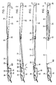
- Fign. 1 bis 4 Längsschnitte durch ein Lüfterdach mit Windabweiser bei verschiedenen Stellungen des Deckels,
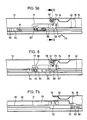
- Fign. 5a und 5b in größerem Maßstab einen Längsschnitt entsprechend Fig. 1, der Einzelheiten der Verstellmechanik des Deckels und des Windabweisers erkennen läßt,
- Fig. 6 einen Teillängsschnitt entsprechend Fig. 5b bei in der Lüfterstellung gemäß Fig. 2 stehendem Deckel,
- Fign. 7a und 7b einen Längsschnitt entsprechend den Fign. 5a und 5b bei teilweise zurückgeschobenem Deckel,
- Fig. 8 eine Teildraufsicht auf das Lüfterdach bei in der Schließstellung entsprechend den Fign. 1, 5a und 5b stehendem Deckel,
- Fig. 9 den Schnitt entlang der Linie IX-IX der Fig. 5a,
- Fig. 10 den Schnitt entlang der Linie X-X der Fig. 5b,
- Fig. 11 den Schnitt entlang der Linie XI-XI der Fig. 7a,
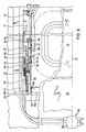
- Fig. 12 einen Schnitt entsprechend der Fig. 7a für eine abgewandelte Ausführungsform des Lüfterdaches,
- Fig. 13 einen Teillängsschnitt durch das Lüfterdach gemäß Fig. 12 bei in der Lüfterstellung stehendem Deckel,
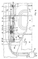
- Fig. 14 eine Teildraufsicht auf das Dach nach den Fign. 12 und 13 bei in Schließstellung stehendem Deckel, wobei das Windabweiserblatt zusätzlich in strichpunktierten Linien auch in seiner ausgestellten Lage angedeutet ist,
- Fig. 15 den Schnitt entlang der Linie XV-XV der Fig. 13, und
- Fig. 16 den Schnitt entlang der Linie XVI-XVI der Fig. 12.
- Fig. 1 to 4 longitudinal sections through a fan roof with wind deflector at different positions of the cover,
- Fig. 5a and 5b on a larger scale a longitudinal section corresponding to FIG. 1, which shows details of the adjustment mechanism of the cover and the wind deflector,
- 6 shows a partial longitudinal section corresponding to FIG. 5b with the cover standing in the fan position according to FIG. 2, FIG.
- Fig. 7a and 7b a longitudinal section corresponding to FIGS. 5a and 5b with the cover partially pushed back,
- Fig. 8 is a partial plan view of the fan roof when in the closed position corresponding to Figs. 1, 5a and 5b standing lid,
- 9 shows the section along the line IX-IX of FIG. 5a,
- 10 shows the section along the line XX of FIG. 5b,
- 11 shows the section along the line XI-XI of FIG. 7a,
- 12 shows a section corresponding to FIG. 7a for a modified embodiment of the fan roof,
- 13 shows a partial longitudinal section through the fan roof according to FIG. 12 with the cover in the fan position,
- 14 is a partial top view of the roof according to FIGS. 12 and 13 with the cover in the closed position, the wind deflector blade also being indicated in dashed lines in its extended position,
- Fig. 15 shows the section along the line XV-XV of Fig. 13, and
- 16 shows the section along the line XVI-XVI of FIG. 12.
Entsprechend der schematischen Darstellung der Fign. 1 bis 4 weist das veranschaulichte Fahrzeugdach einen Deckel 12 mit einer ringsumlaufenden, zweiteiligen Dichtung 14 auf, die auf einen abgesetzten Randflansch 16 des Deckels aufgesetzt ist. Anstelle einer zweiteiligen Dichtung kann gemäß den Fign. 5a, 5b, 6, 9, 10 und 15 auch eine einteilige Dichtung 14′ vorgesehen sein. Mittels des Deckels 12 kann entsprechend Fig. 1 ein Dachausschnitt 17 in einer festen Dachhaut 18 verschlossen werden. Der Deckel 12 läßt sich mittels einer Verstellmechanik um eine (gedachte) an oder nahe seiner Hinterkante 19 liegende Schwenkachse in eine Lüfterstellung gemäß Fig. 2 schwenken, in welcher die Deckelvorderkante 20 in Abstand unterhalb der bei 21 angedeuteten Dachebene liegt. Dabei wird die Deckelhinterkante 19 mindestens näherungsweise in Höhe der festen Dachhaut 18 gehalten. Wenn während der Fahrt des Fahrzeuges an der Außenseite der Dachhaut 18 ein Unterdruck gegenüber dem im Fahrgastraum herrschenden Druck entsteht, bildet sich ein Luftstrom 22 (Fig. 2) aus, der mittels eines nach vorne unter die Dachhaut 18 geschobenen Windabweisers 102 geführt wird. Das Wageninnere wird durch den Spalt 23 zwischen Deckelvorderkante und fester Dachhaut entlüftet.According to the schematic representation of FIGS. 1 to 4, the vehicle roof illustrated has a
Der im vorderen Teil der festen Dachhaut 18 ausgebildete Dachausschnitt 17 läßt sich mindestens teilweise freilegen, indem der Deckel 12 mit seiner Hinterkante 19 unter die Dachhaut abgesenkt und in eine Schiebestellung im wesentlichen parallel zu der Dachebene 21 gebracht (Fig. 3), sowie dann nach hinten unter die Dachhaut 18 geschoben wird (Fig. 4). Der Deckel 12 wird dabei in einem Raum 24 zwischen dem an den Dachausschnitt 17 nach hinten anschließenden Teil der Dachhaut 18 und einem darunter liegenden Festhimmel 25 aufgenommen. Im Zuge des Zurückschiebens des Deckels 12 bewegt sich der Windabweiser 102 so weit nach hinten, daß er ausgestellt werden und den Fahrtwind über den Dachausschnitt 17 ablenken kann. Der Festhimmel 25 kann in nicht näher dargestellter Weise (z.B. entsprechend der Anordnung gemäß der DE-Patentanmeldung P 38 07 961.5) bei 26 an eine dachfeste Querstrebe 27 um eine Querachse verstellbar angelenkt und mit seinem vorderen Ende 28 nach oben federnd vorgespannt sein (Fign. 1 und 2). Beim Absenken der Deckelhinterkante 19 in die Schiebestellung gemäß Fig. 3 wird der Festhimmel 25 von dem Deckel 12 vorne nach unten gedrückt, um den Deckel 12 in den Raum 24 einschieben zu können (Fign. 3 und 4).The
Die Begriffe "vorne" und "hinten" beziehen sich vorliegend auf die Vorwärtsfahrtrichtung des Kraftfahrzeuges, in welches das Dach eingebaut ist. Des weiteren ist das erläuterte Fahrzeugdach einschließlich seiner Stellmechanik im wesentlichen spiegelsymmetrisch mit Bezug auf eine Längsmittelachse 31 (Fig. 8) aufgebaut. Die nachstehende Erläuterung bezieht sich auf die in der Draufsicht rechte Dachseite, gilt jedoch entsprechend auch für die linke Dachseite.In the present case, the terms “front” and “rear” refer to the forward direction of travel of the motor vehicle in which the roof is installed. Furthermore, the vehicle roof, including its adjusting mechanism, is constructed essentially mirror-symmetrically with respect to a longitudinal central axis 31 (FIG. 8). The following explanation refers to the roof side on the right in the top view, but also applies accordingly to the left roof side.
Die Verstellbewegungen werden dem Deckel 12 von einem insgesamt mit 32 bezeichneten Antrieb aufgezwungen, der zwei Antriebskabel 33, beispielsweise in Form von drucksteifen Gewindekabeln, aufweist, die mittels einer gemeinsamen Antriebseinrichtung in Längsrichtung verstellt werden können. In den Fign. 1 bis 4 ist als Antriebseinrichtung ein Antriebsmotor 34 mit nachgeschaltetem Untersetzungsgetriebe 35 angedeutet. Die Fig. 8 zeigt als Alternative dazu eine Antriebseinrichtung in Form einer Handkurbel 36. Die Antriebseinrichtung 34 bzw. 36 treibt ein Ritzel 37 an, das mit beiden Antriebskabeln 33 in Antriebsverbindung steht. Zu beiden Seiten des Dachausschnitts 17 erstreckt sich jeweils eine Längsführung 39, die beispielsweise als dachfest montierte Führungsschiene oder als Teil eines Dachrahmens ausgebildet sein kann. Jede der Längsführungen 39 umfaßt einen Kabelführungskanal 40 für das der jeweiligen Dachseite zugeordnete Antriebskabel 33, einen Kabelführungskanal 41 für das auslaufseitige Ende des der anderen Dachseite zugeordneten Antriebskabels 33 sowie eine Gleitbahn 42. Letztere ist zum Dachausschnitt 17 hin offen.The adjustment movements are forced on the
Die dem Verstellen des Deckels 12 dienende Stellmechanik weist eine vordere Höhenverstelleinrichtung 44 und eine hintere Höhenverstelleinrichtung 45 auf, die unter dem Einfluß der Verstellbewegung der Antriebskabel 33 unabhängig voneinander betätigbar sind.The adjusting mechanism used to adjust the
Zu der vorderen Höhenverstelleinrichtung 44 gehört ein zwangsverstellbarer Schwenkhebel 46, der im Bereich seines vorderen Endes für eine Drehbewegung um eine feststehende, quer zur Deckelverschieberichtung verlaufende, mindestens nahezu waagrechte Achse 47 gelagert ist. Für diesen Zweck erstreckt sich ein zylindrischer Vorsprung 48 einer an das vordere Ende der Längsführung 39 anschließenden, dachfesten Kulisse 49 durch eine Öffnung am vorderen Ende des Schwenkhebels 46 hindurch. Der Schwenkhebel 46 und die Kulisse 49 werden über eine in eine Gewindebohrung 50 der Kulisse 49 eingeschraubte Schraube 51 zusammengehalten. In Längsrichtung des Schwenkhebels 46 erstreckt sich eine Kulissenbahn 52, in die ein Kulissenzapfen 53 eingreift. Der Kulissenzapfen 53 ist Teil eines Mitnehmers 54, der über eine Verdrehsicherung 55 mit dem Antriebskabel 33 verbunden ist und dessen Längsbewegungen mitmacht. Die Kulissenbahn 52 geht im Bereich des hinteren Endes des Schwenkhebels 46 in eine nach hinten offene Führungsbahn 57 über. An dem Deckel 12 oder einem deckelfesten Teil 71 ist ein Gleitelement 58 angebracht, das sich entsprechend den Fign. 5 und 8 in die Führungsbahn 57 einlegt, wenn der Deckel 12 seine vordere Endstellung (Fign. 1, 2 und 3) einnimmt.The front
In der Gleitbahn 42 der Längsführung 39 ist ein Riegelstück 64 in Längsrichtung verschiebbar geführt, das über eine Stange 65 mit dem Mitnehmer 54 und damit dem Antreibskabel 33 fest verbunden ist. Hinter dem Riegelstück 64 sitzt ein in der Gleitbahn 42 längsverschiebbares Gleitstück 66, an dem das eine Ende eines Ausstellhebels 67 der hinteren Höhenverstelleinrichtung 45 für eine Schwenkbewegung um eine waagrechte Querachse 68 angelenkt ist. Für diesen Zweck greift ein zylindrischer Ansatz 69 des Gleitstücks 66 in eine komplementäre Bohrung des Ausstellhebels 67 ein (Fig. 10). Das deckelfeste Teil 71 ist mit dem anderen Ende des Ausstellhebels 67 über einen Gelenkbolzen 72 verbunden, auf dem eine Rolle 73 drehbar gelagert ist. Der Ausstellhebel 67 trägt eine weitere Rolle 74.In the
Im Bereich der Hinterkante 76 des Dachausschnitts 17 ist eine mit der Längsführung 39 zusammenwirkende, dachfeste Kulisse 77 angeordnet. Die Kulisse 77 bildet eine nach unten und hinten weisende Nockenbahn 78 sowie einen vor der Nockenbahn 78 liegenden Kulissenschlitz 79. Im vorderen Teil der Kulisse 77 ist eine sich nach unten in die Gleitbahn 42 öffnende Ausnehmung 80 ausgebildet, die, wenn der Deckel 12 in seiner vorderen Endstellung steht, den oberen Teil eines Riegelsteins 82 aufnimmt (Fig. 5), der in einer Durchgangsöffnung 83 des Gleitstücks 66 senkrecht zur Verschieberichtung dieses Gleitstücks gleitbeweglich geführt ist. In dem Riegelstück 64 ist eine sich nach oben öffnende Ausnehmung 91 ausgebildet, die den unteren Teil des Riegelsteins 82 aufnehmen kann.In the area of the
Der im Bereich der Vorderkante 101 des Dachausschnitts 17 angeordnete Windabweiser 102 ist mit einem Windabweiserblatt 103 ausgestattet, das bei der Ausführungsform gemäß den Fign. 5 bis 11 als Blechbiegeteil ausgebildet ist, an dem beidseits jeweils ein Seitenteil 104 befestigt ist. In zwei in Abstand voneinan der liegende Querbohrungen 105 des Seitenteils 104 ist jeweils ein Stift 106 bzw. 107 eingesetzt. Die Stifte 106 und 107 stehen über das Seitenteil 104 nach außen seitlich vor. Der Stift 107 bildet zusammen mit einem entsprechenden Stift des Seitenteils auf der anderen Seite des Windabweisers 102 eine quer zur Fahrzeuglängsrichtung verlaufende Schwenkachse 108. Für diesen Zweck ist das freie Ende des Stifts 107 in einer Bohrung 109 eines Lagerbocks 110 drehbar gelagert. Der Lagerbock 110 ist seinerseits in einer Führungsbahn 111 einer an die Längsführung 39 nach vorne anschließenden, dachfesten Kulisse 112 in Fahrzeuglängsrichtung verschiebbar gelagert. Das freie Ende des Stifts 106 ist in einem Kulissenschlitz 113 der Kulisse 112 geführt. Der Kulissenschlitz 113 weist einen zu der Führungsbahn 111 parallelen vorderen Abschnitt 114 und einen daran hinten anschließenden, nach oben abgewinkelten hinteren Abschnitt 115 auf.The
Eine Zugfeder 116 erstreckt sich unter Vorspannung zwischen einem dachfesten Widerlager 117 und einem von dem Lagerbock 110 hochstehenden Widerlager 118. Die Zugfeder 116 sucht den Lagerbock 110 entlang der Führungsbahn 111 nach hinten zu ziehen. Der Stift 107 durchgreift drehbar eine zylindrische Bohrung einer Schubstange 119, deren vorderes Ende zwischen das Seitenteil 104 und den Lagerbock 110 reicht, wie dies aus Fig. 11 zu erkennen ist. Die Schubstange 119 trägt an ihrem hinteren Ende ein Druckstück 120, das mittels eines dachfesten Führungsteils 121 parallel zu der Längsführung 39 verschiebbar geführt ist. In der Schubstange 119 ist ein Kulissenschiltz 122 mit einem zu der Gleitbahn 42 parallelen vorderen Abschnitt 123 und einem nach oben rechtwinklig abgewinkelten hinteren Abschnitt 124 ausgebildet. In dem Kulissenschlitz 122 ist der Kulissenzapfen 53 verschiebbar geführt.A
Das veranschaulichte Fahrzeugdach funktioniert wie folgt:The illustrated vehicle roof works as follows:
Befindet sich der Deckel 12 in der Schließstellung gemäß den Fign. 1, 5a, 5b und 8, ist der Schwenkhebel 46 um die Achse 47 in die in Fig. 5a dargestellte Lage geschwenkt, in welcher das deckelfeste Gleitelement 58 von der gabelförmigen Führungsbahn 57 des Schwenkhebels 46 gefaßt und nach oben in eine Stellung gebracht ist, in welcher die Deckelvorderkante 20 mit der Vorderkante 101 des Dachausschnitts 17 mindestens nahezu bündig liegt. Der Ausstellhebel 67 nimmt eine im wesentlichen lotrechte Stellung (Fig. 5b) ein, in welcher der Gelenkbolzen 72 das deckelfeste Teil 71 in eine solche Lage bringt, daß die Hinterkante 19 des Deckels 12 mit der Hinterkante 76 des Dachausschnitts 17 mindestens nahezu bündig liegt. Der Riegelstein 82 greift in die Ausnehmung 80 der Kulisse 77 ein. Damit sind das Gleitstück 66 und, über die Stange 65, der Mitnehmer 54 gegen Verschiebebewegungen mit Bezug auf dachfeste Teile gesichert.If the
Ein deckelfest angebrachtes Stellglied 127 drückt von hinten auf das Druckstück 120, wodurch dieses zusammen mit der daran angebrachten Schubstange 119 entgegen der Kraft der Zugfeder 116 in seiner vorderen Endstellung gehalten wird. Mittels der Schubstange 119 ist auch der Stift 107 und infolgedessen die Schwenkachse 108 des Windabweisers 102 in die in den Fign. 5a und 8 dargestellte vordere Endlage gebracht. Der Stift 106 steht in dem vorderen Abschnitt 114 des Kulissenschlitzes 113. Dadurch wird dem Windabweiserblatt 103 die insbesondere aus der Fig. 5a zu erkennende Schwenklage aufgezwungen, in welcher der der Schwenkachse 108 naheliegende Teil 128 des Windabweiserblattes 103 schräg nach hinten und oben geneigt ist. Der Windabweiser 102 ist als Ganzes in einen Aufnahmeraum 129 vorgeschoben, der vor der Vorderkante 101 des Dachausschnitts 17 liegt. In dieser Außerbetriebsstellung bildet der Windabweiser 102 eine Luftleitfläche, die den in Fig. 2 angedeuteten Luftstrom 22 aus dem Fahrzeuginnenraum gezielt zu dem Spalt 23 leitet, der zwischen der Vorderkante 101 des Dachausschnitts 17 und der Vorderkante 20 des in die Lüfterstellung abgesenkten Deckels 12 entsteht. Bei offenem Dach wird der Schwenkhebel 46 dadurch in der abgesenkten Position gehalten, daß sich ein mit dem Schwenkhebel 46 fest verbundener Kulissenstift 125 in den Abschitt 123 des Kulissenschlitzes 122 einlegt.A cover-mounted
Soll der Deckel 12 ausgehend von der Schließstellung in die Lüfterstellung gemäß Fig. 2 gebracht werden, wird über den Antriebsmotor 34 oder die Handkurbel 36 das Antriebskabel 33 mit seinem antriebsseitigen Ende nach hinten verstellt. Dabei wird über den Mitnehmer 54 der Kulissenzapfen 53 entlang einem vorderen Abschnitt 92 der Kulissenbahn 52 nach hinten verstellt. Wandert dann anschließend der Kulissenzapfen 53 entlang dem an den Abschnitt 92 anschließenden, nach hinten ansteigenden Abschnitt 93 der Kulissenbahn 52 entlang, wird der Schwenkhebel 46 von der in Fig. 5a dargestellten Stellung aus im Uhrzeigersinn (in Fig. 5a) um die dachfeste Achse 47 geschwenkt. Der Schwenkhebel 46 nimmt dabei das deckelfeste Gleitelement 58 nach unten mit. Letzteres taucht über eine Ausnehmung 94 der oberen Begrenzungswand 95 der Gleitbahn 42 in die Gleitbahn ein.If the
Aufgrund der Schwenkbewegung des Schwenkhebels 46 wird der Deckel um eine von den Gelenkbolzen 72 bestimmte Schwenkachse 98 aus der Schließstellung in die Lüfterstellung (Fign. 2 und 6) verschwenkt. Die Deckelvorderkante 20 wird abgesenkt, und das vordere Ende des Stellglieds 127 gleitet entlang dem Druckstück 120 nach unten. Die Schubstange 119 wird durch den Eingriff zwischen dem Kulissenstift 125 und dem Kulissenschlitzabschnitt 124 weiterhin in ihrer vorderen Endstellung gehalten. Über den Spalt 23 (Fig. 2) kann der Wageninnenraum wirkungsvoll entlüftet werden, wobei der Windabweiser 102 den Luftstrom 22 gezielt durch den Spalt 23 leitet.Due to the pivoting movement of the
Beim Übergang des Deckels 12 von der Schließ- in die Lüfterstellung hat sich das Riegelstück 64 in die in Fig. 6 veranschaulichte Stellung bewegt, in welcher das Riegelstück 64 an dem Gleitstück 66 anliegt, um letzteres nach hinten mitzunehmen. Der Riegelstein 82 hat die Ausnehmung 80 verlassen und sich stattdessen mit seinem unteren Ende in die Ausnehmung 91 des Riegelstücks 64 eingelegt. Dadurch wird die Arretierung des Gleitstücks 66 aufgehoben. Das Gleitstück 66 wird über den Riegelstein 82 mit dem Riegelstück 64 sowie über die Stange 65 und den Mitnehmer 54 mit dem Antriebskabel 33 auf Mitnahme gekuppelt.During the transition of the
Bei weiterem Verstellen des Antriebskabels 33 nach hinten kommt das Gleitelement 58 außer Eingrifft mit dem Schwenkhebel 46. Das Gleitelement 58, tritt in die Gleitbahn 42 über. Das Riegelstück 64 und das Gleitstück 66 bewegen sich gemeinsam nach hinten. Durch den Eingriff der Rolle 73 mit dem Kulissenschiltz 79 wird der Ausstellhebel 67 entgegen dem Uhrzeigersinn (in den Fign. 5b, 6 und 7b) in die in Fig. 7b veranschaulichte Stellung geschwenkt. Dadurch wird der Deckel 12 im Bereich seiner Hinterkante 19 abgesenkt (Fign. 3 und 7b), wobei die Rolle 73 von dem Kulissenschiltz 79 in die Gleitbahn 42 übergeht. Der Deckel 12 kann jetzt parallel zur festen Dachhaut 18 nach hinten geschoben werden (Fig. 4). Wenn die Horizontalbewegung des Deckels 12 nach hinten einsetzt, bewegen sich synchron zu dem deckelfesten Stellglied 127 auch das Druckstück 120, die Schubstange 119, der Lagerbock 110 und damit die Schwenkachse 108 und der Windabweiser 102 unter dem Einfluß der Zugfeder 116 geradlinig nach hinten. Diese Bewegung wird dadurch ermöglicht, daß mit dem Absenken der Deckelvorderkante der Kulissenstift 125 des Schwenkhebels 46 in dem Kulissenschlitzabschnitt 124 nach unten gewandert ist und in den Abschnitt 123 des Kulissenschlitzes 122 eintreten kann. In der letzten Phase der Verschiebebewegung des Windabweisers 102 nach hinten wird das Windabweiserblatt 103 dann durch Zusammenwirken zwischen dem Stift 106 und dem gekrümmten hinteren Abschnitt 115 des Kulissenschlitzes 113 aufgerichtet und in seine ausgestellte Betriebslage gebracht, die in Fig. 7a veranschaulicht ist. In dieser Stellung steht der Teil 128 des Windabweiserblattes 103 lotrecht oder nahezu lotrecht, wobei dieses Teil 128 eine Sichtblende bildet, welche den unterhalb der Vorderkante 101 des Dachausschnitts 17 liegenden Spalt gegen Sicht vom Wageninneren her abdeckt. Das an den Teil 128 nach oben anschließende abgewinkelte Ende 130 des Windabweiserblattes 103 ragt über die feste Dachhaut 18 vor, um den Fahrtwind nach oben abzulenken.With further adjustment of the
Wird die Antriebsrichtung umgekehrt, wird aufgrund der Kupplung zwischen Riegelstück 64 und Gleitstück 66 der Deckel 12 wieder nach vorne geschoben, bis die Rolle 74 auf die Nockenbahn 78 der Kulisse 77 trifft. Bei weiterer Vorbewegung des Gleitstücks 66 wird der Ausstellhebel 67 durch das Zusammenwirken von Rolle 74 und Nockenbahn 78 im Uhrzeigersinn (in Fig. 7b) geschwenkt. Die Rolle 73 tritt aus der Gleitbahn 42 in den Kulissenschlitz 79 über. Der Deckel 12 wird hinten hochgestellt (Fign. 2 und 6). Dabei erreichen das Riegelstück 64 und das Gleitstück 66 wieder die in Fig. 6 veranschaulichte Stellung. Der Riegelstein 82 wird nach oben geschoben und kommt dadurch von dem Riegelstück 64 frei. Er legt sich in die Ausnehmung 80 ein, so daß das Gleitstück 66 wieder mit Bezug auf die Kulisse arretiert ist. Kurz nach Durchlaufen der Stellung gemäß Fig. 7b hat das Stellglied 127 das Druckstück 120 nach vorne entgegen der Kraft der Zugfeder 116 mitgenommen. Die Windabweiser-Schwenkachse 108 wird entsprechend nach vorne verlagert, und durch das gleichzeitige Zusammenwirken von Stift 106 und Kulissenschlitz 113 wird das Windabweiserblatt 103 im Uhrzeigersinn (in den Fign. 5a und 7a) verschwenkt. Der so in die Außerbetriebsstellung geschwenkte Windabweiser 102 wird in den vor der Vorderkante 101 des Dachausschnitts 17 liegenden Aufnahmeraum 129 geschoben.If the drive direction is reversed, the
Beim Vorbewegen des Antriebskabels 33 tritt der Kulissenzapfen 53 in die Kulissenbahn 52 ein und bewegt sich zunächst entlang deren hinterem Abschnitt 97, der bei abgesenkter Deckelvorderkante parallel zu der Gleitbahn 42 verläuft. Wenn der Kulissenzapfen 53 dann den mittleren Kulissenbahnabschnitt 93 erreicht, ist das deckelfeste Gleitelement 58 in die Führungsbahn 57 des Schwenkhebels 46 eingetreten. Durch weiteres Vorbewegen des Mitnehmers 54 wird der Schwenkhebel 46 aufgrund des gegenseitigen Eingriffes von Kulissenzapfen 53 und Abschnitt 93 der Kulissenbahn 52 um die dachfeste Achse 47 entgegen dem Uhrzeigersinn (in Fig. 5a) verschwenkt. Der Deckel 12 wird vorne angehoben. Er hat damit wieder seine Schließstellung (Fign. 5a und 5b) erreicht.When the
Bei der in den Fign. 12 bis 16 veranschaulichten abgewandelten Ausführungsform ist der Windabweiser 102′ als Formteil ausgebildet, bei dem das Windabweiserblatt 103′ und die Seitenteile 104′ einstückig untereinander verbunden sind. Im übrigen unterscheidet sich diese Ausführungsform von der zuvor erläuterten Ausführungsform im wesentlichen nur dadurch, daß die Schubstange 119′ mit dem Stellglied 127′ zwecks Betätigung des Windabweisers 102′ für Längsbewegungen in beiden Richtungen selbsttätig gekuppelt wird, wenn sich der Deckel 12 im Zuge seine Verstellbewegung in Fahrzeuglängsrichtung der vorderen Endstellung bis auf einen vorbestimmten Abstand genähert hat. Die Schubstange 119′ und das Stellglied 127′ werden umgekehrt selbsttätig wieder voneinander entkuppelt, wen sich der Deckel 12 ausgehend von der vorderen Endstellung um einen vorbestimmten Betrag nach hinten bewegt hat. Für diesen Zweck sind die Schubstange 119′ und das Stellglied 127′ mit Klauen 133 bzw. 134 ausgestattet. Nähert sich beim Vorschieben des Deckels 12 das Stellglied 127′ der Schubstange 119′ (Fig. 12), legt sich die Klaue 134 über die Klaue 133. Sobald dann das Stellglied 127′ mit seiner Vorderkante 135 an der Hinterkante 136 Schubstange 119′ anstößt. wird die Schubstange 119′ von dem Stellglied 127′ nach vorne mitgenommen. Dabei wird durch das Zusammenwirken zwischen einem dachfest angebrachten Kulissenstift 137 und einem in der Schubstange 119′ ausgebildeten zusätzlichen Kulissenschlitz 138 die Schubstange 119′ hinten angehoben. Die Klauen 133 und 134 werden dadurch in formschlüssige gegenseitige Verbindung gebracht. Der in diesem Fall mit der Schubstange 119′ einstückig verbundene Lagerbock 110′ wird entlang der Führungsbahn 111′ der Kulisse 112′ nach vorne geschoben. Durch das Zusammenwirken des Stifts 106′ mit dem Kulissenschlitz 113′ der Kulisse 112′ wird das Windabweiserblatt 103′ in die in Fig. 13 veranschaulichte Schräglage gebracht und in den Aufnahmeraum 129′ unter der festen Dachhaut 18′ vorbewegt, bis die Schubstange 119′ an einem dachfesten Puffer 139 anliegt.In the case of the figures 12 to 16 illustrated modified embodiment, the wind deflector 102 'is formed as a molded part in which the wind deflector blade 103' and the side parts 104 'are integrally connected to one another. Otherwise, this embodiment differs from the previously explained embodiment essentially only in that the push rod 119 'with the actuator 127' for the purpose of actuating the wind deflector 102 'is automatically coupled for longitudinal movements in both directions when the
Beim Zurückschieben des Deckels 12′ wird die Schubstange 119′ von dem Stellglied 127′ über die miteinander in Eingriff stehenden Klauen 133 und 134 mitgenommen. Die Schwenkachse 108′ des Windabweisers 102′ wird wieder nach hinten verlagert. Durch Einlaufen des Stifts 106′ in den gekrümmten hinteren Abschnitt 115′ des Kulissenschlitzes 113′ wird das Windabweiserblatt 103′ aufgestellt (Fign. 12 und 16 sowie gestrichelte Darstellung in Fig. 14). Kurz bevor der Windabweiser 102′ seine aufgestellte Endlage erreicht, steuert der Kulissenstift 137 die Schubstange 119′ über den vorderen abgeknickten Abschnitt 140 des Kulissenschlitzes 138 nach unten. Dadurch wird der Formschluß zwischen den Klauen 133 und 134 gelöst (Fig. 12). Die letzte Phase der Aufstellbewegung des Windabweisers 102′ erfolgt unter dem Einfluß einer Schenkelfeder 141, die an dem Stift 106′ angreift und die sich vorne gegen die Schubstange 119′ abstützt. Die Schenkelfeder 141 drückt dabei die Schubstange 119′ gegen einen (nicht dargestellten) Anschlag der Kulisse 112′. Der Schwenkhebel 46′ wird über den Kulissenschlitz 122′ der Schubstange 119′ und den Kulissenstift 125′ so fixiert, daß beim Schließen des Deckels 12′ das Gleitelement 58′ am Stellglied 127′ wieder sauber in die gabelförmige Führungsbahn 57′ einfädelt.When pushing back the cover 12 ', the push rod 119' is taken from the actuator 127 'via the mutually
Die vorstehend in Verbindung mit einem Lüfterdach erläuterte Windabweiseranordnung eignet sich auch für beliebige andere Dachtypen mit mindestens einem mittels einer Abdeckung verschließbaren Dachausschnitt, beispielsweise für Schiebedächer, Schiebehebedächer, Spoilerdächer und Faltdächer.The wind deflector arrangement explained above in connection with a fan roof is also suitable for any other roof types with at least one roof cutout which can be closed by means of a cover, for example for sunroofs, sunroofs, spoiler roofs and folding roofs.
Claims (9)
Applications Claiming Priority (2)
| Application Number | Priority Date | Filing Date | Title |
|---|---|---|---|
| DE3916906 | 1989-05-24 | ||
| DE3916906A DE3916906C1 (en) | 1989-05-24 | 1989-05-24 |
Publications (1)
| Publication Number | Publication Date |
|---|---|
| EP0399166A1 true EP0399166A1 (en) | 1990-11-28 |
Family
ID=6381307
Family Applications (1)
| Application Number | Title | Priority Date | Filing Date |
|---|---|---|---|
| EP90105529A Withdrawn EP0399166A1 (en) | 1989-05-24 | 1990-03-23 | Vehicle roof with wind deflector |
Country Status (4)
| Country | Link |
|---|---|
| US (1) | US5052746A (en) |
| EP (1) | EP0399166A1 (en) |
| JP (1) | JP2834269B2 (en) |
| DE (1) | DE3916906C1 (en) |
Cited By (3)
| Publication number | Priority date | Publication date | Assignee | Title |
|---|---|---|---|---|
| EP0955193A2 (en) * | 1998-05-08 | 1999-11-10 | WEBASTO KAROSSERIESYSTEME GmbH | Vehicle roof with sliding plate and wind deflector |
| DE19907806C2 (en) * | 1999-02-24 | 2000-12-21 | Webasto Vehicle Sys Int Gmbh | Openable vehicle roof with extendable wind deflector |
| EP2208628A3 (en) * | 2009-01-20 | 2010-10-06 | Advanced Comfort Systems France - ACS France | Device forming a glazed part of a motor vehicle roof, fitted with a deflector |
Families Citing this family (16)
| Publication number | Priority date | Publication date | Assignee | Title |
|---|---|---|---|---|
| DE4123229C2 (en) * | 1991-07-13 | 1994-02-24 | Webasto Ag Fahrzeugtechnik | Vehicle roof with a series of sliding slats |
| DE4129860C1 (en) * | 1991-09-07 | 1992-09-17 | Webasto Ag Fahrzeugtechnik, 8035 Stockdorf, De | |
| DE4233507C1 (en) * | 1992-10-06 | 1993-11-11 | Webasto Karosseriesysteme | Vehicle roof with a series of slats |
| DE19809943C5 (en) * | 1998-03-07 | 2006-01-05 | Webasto Ag | Vehicle wind deflector with adjustable installation speed depending on the vehicle speed |
| NL1013832C2 (en) * | 1999-12-13 | 2001-06-14 | Inalfa Ind Bv | Open roof construction for a vehicle. |
| DE10146285B4 (en) * | 2001-03-19 | 2007-03-29 | Webasto Ag | vehicle roof |
| DE10121888A1 (en) * | 2001-05-05 | 2002-11-28 | Porsche Ag | Roof arrangement for a vehicle |
| DE10208185B4 (en) | 2002-02-20 | 2006-02-02 | Webasto Ag | Wind deflector arrangement for a vehicle roof |
| FR2839283B1 (en) * | 2002-05-06 | 2004-10-08 | Webasto Systemes Carrosserie | DEFLECTOR SYSTEM FOR A SUNROOF VEHICLE, WITH LOW STORAGE THICKNESS |
| US6705673B1 (en) | 2002-09-27 | 2004-03-16 | Honda Giken Kogyo Kabushiki Kaisha | Latched wind deflector system |
| US6666503B1 (en) | 2002-09-27 | 2003-12-23 | Honda Giken Kogyo Kabashiki Kaishu | Pop-up vehicle wind deflector |
| CN102514466B (en) * | 2011-12-15 | 2014-12-10 | 潍柴动力股份有限公司 | Skylight of commercial vehicle |
| US8459729B1 (en) | 2012-03-16 | 2013-06-11 | Webasto Roof Systems Inc. | Wind deflector assemblies for an opening of a vehicle roof |
| DE102013108891B4 (en) * | 2013-08-16 | 2019-12-05 | Webasto SE | Wind deflector with opening mechanism |
| US10507713B2 (en) * | 2017-03-23 | 2019-12-17 | Magna Mirrors Of America, Inc. | Wind deflector assembly for vehicle roof |
| DE102018222785A1 (en) * | 2018-12-21 | 2020-06-25 | Bos Gmbh & Co. Kg | Wind protection device for an openable roof section of a motor vehicle |
Citations (3)
| Publication number | Priority date | Publication date | Assignee | Title |
|---|---|---|---|---|
| DE2416173A1 (en) * | 1974-04-03 | 1975-10-16 | Webasto Werk Baier Kg W | Wind deflector for sliding roof panel - with hidden operating rods which slide over each other for compact storage |
| DE2607816A1 (en) * | 1976-02-26 | 1977-09-01 | Webasto Werk Baier Kg W | WIND DEFLECTOR ARRANGEMENT ON A MOTOR VEHICLE ROOF |
| DE3137191A1 (en) * | 1981-09-18 | 1983-03-31 | Rockwell Golde Gmbh, 6000 Frankfurt | WIND RESISTANT DEVICE ON A MOTOR VEHICLE ROOF |
Family Cites Families (6)
| Publication number | Priority date | Publication date | Assignee | Title |
|---|---|---|---|---|
| DE578111C (en) * | 1933-06-09 | Linke Hofmann Busch Werke Akt | Roof for observation car | |
| FR2261893B1 (en) * | 1974-02-26 | 1976-06-25 | Peugeot & Renault | |
| DE3426998A1 (en) * | 1984-07-21 | 1986-01-30 | Webasto-Werk W. Baier GmbH & Co, 8035 Gauting | Vehicle roof |
| DE3539987A1 (en) * | 1985-11-11 | 1987-05-14 | Weinsberg Karosseriewerke | Draught deflector for the sliding roof of a motor vehicle |
| DE3840694A1 (en) * | 1988-03-10 | 1990-06-07 | Webasto Ag Fahrzeugtechnik | FAN ROOF FOR MOTOR VEHICLES |
| DE3807961A1 (en) * | 1988-03-10 | 1989-09-21 | Webasto Ag Fahrzeugtechnik | Ventilation roof for motor vehicles |
-
1989
- 1989-05-24 DE DE3916906A patent/DE3916906C1/de not_active Expired - Fee Related
-
1990
- 1990-03-23 EP EP90105529A patent/EP0399166A1/en not_active Withdrawn
- 1990-04-18 JP JP2104310A patent/JP2834269B2/en not_active Expired - Lifetime
- 1990-05-21 US US07/525,602 patent/US5052746A/en not_active Expired - Fee Related
Patent Citations (3)
| Publication number | Priority date | Publication date | Assignee | Title |
|---|---|---|---|---|
| DE2416173A1 (en) * | 1974-04-03 | 1975-10-16 | Webasto Werk Baier Kg W | Wind deflector for sliding roof panel - with hidden operating rods which slide over each other for compact storage |
| DE2607816A1 (en) * | 1976-02-26 | 1977-09-01 | Webasto Werk Baier Kg W | WIND DEFLECTOR ARRANGEMENT ON A MOTOR VEHICLE ROOF |
| DE3137191A1 (en) * | 1981-09-18 | 1983-03-31 | Rockwell Golde Gmbh, 6000 Frankfurt | WIND RESISTANT DEVICE ON A MOTOR VEHICLE ROOF |
Cited By (4)
| Publication number | Priority date | Publication date | Assignee | Title |
|---|---|---|---|---|
| EP0955193A2 (en) * | 1998-05-08 | 1999-11-10 | WEBASTO KAROSSERIESYSTEME GmbH | Vehicle roof with sliding plate and wind deflector |
| EP0955193A3 (en) * | 1998-05-08 | 2001-05-16 | WEBASTO KAROSSERIESYSTEME GmbH | Vehicle roof with sliding plate and wind deflector |
| DE19907806C2 (en) * | 1999-02-24 | 2000-12-21 | Webasto Vehicle Sys Int Gmbh | Openable vehicle roof with extendable wind deflector |
| EP2208628A3 (en) * | 2009-01-20 | 2010-10-06 | Advanced Comfort Systems France - ACS France | Device forming a glazed part of a motor vehicle roof, fitted with a deflector |
Also Published As
| Publication number | Publication date |
|---|---|
| JPH02310125A (en) | 1990-12-25 |
| JP2834269B2 (en) | 1998-12-09 |
| DE3916906C1 (en) | 1990-06-28 |
| US5052746A (en) | 1991-10-01 |
Similar Documents
| Publication | Publication Date | Title |
|---|---|---|
| EP0150470B1 (en) | Vehicle roof | |
| EP0306647B1 (en) | Vehicle roof with a movable front and rear panels | |
| EP0381066B1 (en) | Vehicle roof with a roof cutout closable by a cover | |
| DE3916906C1 (en) | ||
| DE3908645C1 (en) | ||
| EP2451665B2 (en) | Sliding roof device, in particular for a motor vehicle | |
| EP0399167B1 (en) | Sliding roof for vehicles | |
| EP0331910A2 (en) | Sliding roof for motor vehicles | |
| EP2108536B1 (en) | Vehicle roof with an adjustable cover and a cover drive device | |
| DE3425271A1 (en) | VEHICLE ROOF | |
| DE4238945C1 (en) | Lifting and sliding car-roof - uncouples lifting lever on moving from ventilating to open position and engages with guide rail on top of fixed roof | |
| DE4040825A1 (en) | SLIDING ROOF FOR MOTOR VEHICLES | |
| DE3807961C2 (en) | ||
| EP1338455A1 (en) | Wind deflector arrangement for an openable vehicle roof | |
| DE19634324C2 (en) | Vehicle roof | |
| DE3129900A1 (en) | Tilt-and-slide sunroof for motor vehicles | |
| DE10158174A1 (en) | Sliding roof panel for vehicle has improved front hinge mountings which reduce draughts and protect seals | |
| EP1193094A2 (en) | Device for open roof wind deflector | |
| DE102004042450B4 (en) | vehicle roof | |
| DE2132656A1 (en) | WIND DEFLECTORS FOR THE SUNROOF OF A VEHICLE | |
| DE3438360C2 (en) | ||
| DE3924035C1 (en) | ||
| EP0292730B1 (en) | Vehicle roof | |
| DE10065248B4 (en) | Swiveling and sliding rear window | |
| DE102005037703B4 (en) | Vehicle roof with a sliding above the roof roof part |
Legal Events
| Date | Code | Title | Description |
|---|---|---|---|
| PUAI | Public reference made under article 153(3) epc to a published international application that has entered the european phase |
Free format text: ORIGINAL CODE: 0009012 |
|
| AK | Designated contracting states |
Kind code of ref document: A1 Designated state(s): DE ES FR GB IT NL SE |
|
| 17P | Request for examination filed |
Effective date: 19901222 |
|
| 17Q | First examination report despatched |
Effective date: 19920117 |
|
| STAA | Information on the status of an ep patent application or granted ep patent |
Free format text: STATUS: THE APPLICATION IS DEEMED TO BE WITHDRAWN |
|
| 18D | Application deemed to be withdrawn |
Effective date: 19920528 |