EP0397158A2 - Maschine zum Quetschen von Dosen und ähnlichen Behältern mit getrennter Sammlung derjenigen aus Aluminium und derjenigen aus Feinblech - Google Patents
Maschine zum Quetschen von Dosen und ähnlichen Behältern mit getrennter Sammlung derjenigen aus Aluminium und derjenigen aus Feinblech Download PDFInfo
- Publication number
- EP0397158A2 EP0397158A2 EP90108791A EP90108791A EP0397158A2 EP 0397158 A2 EP0397158 A2 EP 0397158A2 EP 90108791 A EP90108791 A EP 90108791A EP 90108791 A EP90108791 A EP 90108791A EP 0397158 A2 EP0397158 A2 EP 0397158A2
- Authority
- EP
- European Patent Office
- Prior art keywords
- rotor
- crushing
- cans
- contrast
- machine
- Prior art date
- Legal status (The legal status is an assumption and is not a legal conclusion. Google has not performed a legal analysis and makes no representation as to the accuracy of the status listed.)
- Withdrawn
Links
- 229910000806 Latten Inorganic materials 0.000 title claims abstract description 22
- 229910052782 aluminium Inorganic materials 0.000 title claims abstract description 20
- XAGFODPZIPBFFR-UHFFFAOYSA-N aluminium Chemical compound [Al] XAGFODPZIPBFFR-UHFFFAOYSA-N 0.000 title claims abstract description 20
- 230000005484 gravity Effects 0.000 claims abstract description 12
- 239000000463 material Substances 0.000 claims description 8
- 230000005540 biological transmission Effects 0.000 claims description 6
- 230000000284 resting effect Effects 0.000 claims description 5
- 238000000605 extraction Methods 0.000 claims description 3
- 239000007787 solid Substances 0.000 claims description 3
- 230000004308 accommodation Effects 0.000 claims 1
- 235000013361 beverage Nutrition 0.000 description 3
- 235000013305 food Nutrition 0.000 description 2
- 238000005056 compaction Methods 0.000 description 1
- 230000006835 compression Effects 0.000 description 1
- 238000007906 compression Methods 0.000 description 1
- 229910052751 metal Inorganic materials 0.000 description 1
- 239000002184 metal Substances 0.000 description 1
- 238000012986 modification Methods 0.000 description 1
- 230000004048 modification Effects 0.000 description 1
- 230000003287 optical effect Effects 0.000 description 1
- 230000000717 retained effect Effects 0.000 description 1
- 239000002699 waste material Substances 0.000 description 1
Images


Classifications
-
- B—PERFORMING OPERATIONS; TRANSPORTING
- B03—SEPARATION OF SOLID MATERIALS USING LIQUIDS OR USING PNEUMATIC TABLES OR JIGS; MAGNETIC OR ELECTROSTATIC SEPARATION OF SOLID MATERIALS FROM SOLID MATERIALS OR FLUIDS; SEPARATION BY HIGH-VOLTAGE ELECTRIC FIELDS
- B03C—MAGNETIC OR ELECTROSTATIC SEPARATION OF SOLID MATERIALS FROM SOLID MATERIALS OR FLUIDS; SEPARATION BY HIGH-VOLTAGE ELECTRIC FIELDS
- B03C1/00—Magnetic separation
- B03C1/02—Magnetic separation acting directly on the substance being separated
- B03C1/10—Magnetic separation acting directly on the substance being separated with cylindrical material carriers
- B03C1/12—Magnetic separation acting directly on the substance being separated with cylindrical material carriers with magnets moving during operation; with movable pole pieces
-
- B—PERFORMING OPERATIONS; TRANSPORTING
- B30—PRESSES
- B30B—PRESSES IN GENERAL
- B30B3/00—Presses characterised by the use of rotary pressing members, e.g. rollers, rings, discs
- B30B3/02—Presses characterised by the use of rotary pressing members, e.g. rollers, rings, discs co-operating with a fixed member
-
- B—PERFORMING OPERATIONS; TRANSPORTING
- B30—PRESSES
- B30B—PRESSES IN GENERAL
- B30B9/00—Presses specially adapted for particular purposes
- B30B9/32—Presses specially adapted for particular purposes for consolidating scrap metal or for compacting used cars
- B30B9/321—Presses specially adapted for particular purposes for consolidating scrap metal or for compacting used cars for consolidating empty containers, e.g. cans
- B30B9/325—Presses specially adapted for particular purposes for consolidating scrap metal or for compacting used cars for consolidating empty containers, e.g. cans between rotary pressing members, e.g. rollers, discs
Definitions
- the present invention relates to a machine for crushing cans, tins and the like with automatic operation, provided with means for sorting and separately collecting the aluminum cans or tins from white latten cans or tins, these two types of cans or tins for beverages being generally currently commercially available.
- Some kinds of can-crushing machines are also provided with token-box devices which can distribute prize tokens to the users which total a given number of aluminum cans separately from the number of white-latten cans.
- Can-crushing machines usable by private operators normally provide the introduction of the cans into an openable tray or the like, then sorting by means of magnetic-attraction means which deflect sheet-metal cans with respect to aluminum ones, and then the crushing of the cans thus separated by means of a compression which is exerted axially thereto so as to deform the cylindrical body and move the opposite bottoms mutually closer.
- the crushing of the cans is such as to considerably reduce their initial volume and therefore such as to reduce the containers of the crushed bodies, facilitating their transport.
- the aim of the present invention is to provide a machine for crushing cans of beverages in general and cans of other food products, structured so as to obviate the disadvantages and limitations of known machines and most of all capable of subjecting the cans to such a deformation and crushing as to convert them into flattened and thin bodies, with the advantage of offering a greater surface to the magnetic forces which perform sorting and separate collection.
- An object of the invention is to provide a can-crushing machine which is structurally very simple and highly reliable, has a small bulk and requires no preliminary operation for opening or preparing the can loading duct.
- a further object of the invention is to provide a machine of the above specified type which can operate in a fully automatic manner and is also such as to expel any foreign bodies intentionally or accidentally introduced into the machine itself.
- Not least object of the invention is to provide a can-crushing machine which has a high crushing speed and is provided with means for automatically adjusting the degree of crushing according to the dimensions and thicknesses of the cans to be crushed.
- a can-crushing machine with manual feeding which is constituted, according to the present invention, by a box-like containment and supporting body, a rotor being rotatably mounted at the top of said box-like body, said rotor having a horizontal axis and being peripherally provided with teeth in the shape of longitudinal wings which retract into the rotor body in opposition to pre-loaded springs, a vertical contrast plate being located tangent to said rotor so as to allow each can, fed by gravity feed by loading means, to be engaged by said teeth and then crushed between the rotor and the plate until it is flattened and allowed to fall vertically in a tangent direction toward rotating means provided with magnetized cores adapted to retain only white-latten flattened cans, allowing aluminum ones to fall freely into a first underlying container, the white-latten cans being then carried until they are against a fixed stop element capable of making them fall into a second container.
- said vertical contrast plate is mounted so as to be movable on horizontal guides and in opposition to return springs so that it can be spaced from the crushing rotor in the case of presence of foreign bodies or of cans with dimensions and thickness which differ from those normally provided for in crushing.
- Said loading means are furthermore constituted by a tube with a vertical axis which is rigidly mounted at the top of said vertical contrast plate in order to ensure in any case the correct feeding of the cans between the plate and the crushing rotor.
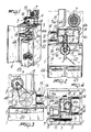
- the machine according to the invention is constituted by a supporting and containment framework 1 in the shape of a cabinet which is open upward and is frontally provided with a swinging door 2.
- a supporting and containment framework 1 in the shape of a cabinet which is open upward and is frontally provided with a swinging door 2.
- Above the cabinet 1 there are two parallel transverse bars 3-3a on which a quadrangular box-like body 4 is fixed; said body is constituted by four uprights to which two mutually opposite vertical containment plates 4a-4b are connected.
- a shaft 5 with a horizontal axis is mounted between the two parallel plates 4a-4b, and a cylindrical rotor 6 with a particular profile, driven by an electric motor 7 by means of pulleys 8 and 9 and a related transmission belt 10 (figures 3 and 4), is keyed on said shaft.
- the rotor 6 is constituted by a cylinder which is peripherally provided with four quadrangular longitudinal grooves 6a, 6b, 6c and 6d (figure 9) which are mutually at 90° and within which rod-like wings or teeth 7a, 7b, 7c and 7d are arranged; said wings are quadrangular and are mounted so as to radially retract into the grooves 6a, 6b, 6c and 6d, and each wing is fixed to the bottom of said grooves by means of a rod 8a, 8b, 8c and 8d (figure 10) which has its own head 9a, 9b, 9c and 9d in abutment within a recess provided in said wing and its opposite end screwed into the bottom of the related groove 6a, 6b, 6c and 6d.
- a rod 8a, 8b, 8c and 8d (figure 10) which has its own head 9a, 9b, 9c and 9d in abutment within a recess provided in said wing and its opposite
- a pre-loaded spring 10a, 10b, 10c and 10d (figure 10) tends to keep the wing in a position which is external to the rotor and at the same time allows said wing to retract and disappear into its own groove when it is radially pressed, as will become apparent hereinafter.
- Two rod-like elements 25-26 and 27-28 are furthermore interposed between each opposite pair of wings, i.e. between the wings 7a-7c and the wings 7b-7d, as shown in figure 10, and are arranged parallel and slidable in a diametrical direction inside the rotor 6.
- the ends of the rod-like elements 25-26 are accommodated within recesses provided in the opposite teeth 7a-7c, whereas those of the other two rods 27-28 are arranged at 90° with respect to the first ones and their ends are accommodated within recesses provided in the other two wings 7b-7d.
- Said four rod-like elements are arranged mutually offset with respect to the axis of rotation O-O of the rotor 6 (figure 10) and their function is to constitute extraction devices capable of extracting a tooth from its own groove when the opposite tooth is pushed so as to disappear into its own groove; when a tooth makes contact with a contrast means, advantageously constituted by a contrast plate 11, the extraction device in fact forces the opposite tooth to exit from its own groove even if said tooth is locked in the groove or its spring has failed.
- the vertical contrast plate 11 is located on the left open side of the box-like body constituted by the two facing plates 4a-4b (figures 1-2 and 5 to 8) and is movably mounted on four horizontal cylindrical rods 12 in contrast with cylindrical return springs 13; said rods 12 are rigidly associated with the vertical edges of the plates 4a-4b and have, at their free ends, a nut 14 for adjusting the loading of the springs 13.
- Said contrast plate 11 is located proximate to the outer cylindrical profile of the rotor 6 so as to leave, between said rotor and said plate, a space which is preset and adjustable, i.e.
- the plate's possibility of moving away from the rotor allows to preserve the integrity of the rotor in case of an arrival of solid foreign bodies larger than a crushed can between the rotor and the plate 11.
- a tubular sleeve 15 is furthermore rigidly associated with said contrast plate 11 by means of a vertical arm 11a and constitutes the means for the gravity loading of one can at a time.
- the position of the loader 15 is provided so that every can is able to reach the rotor 6 and can be guided against the contrast plate 11.
- a shaft 16 is located below the crushing rotor 6 and is rotatably mounted between two opposite arms 17 which are rigidly associated with the horizontal crosspieces 3-3a with an axis of rotation which is parallel to that of the shaft 5 of the rotor.
- the rotary motion of the shaft 16 is drawn from that of the shaft 5 by means of two gears, which are rigidly associated with the two shafts 5 and 16, and of a transmission chain 18.
- a roller 19 is keyed on said shaft 16, and permanently magnetized cores 20 are arranged inside it; their function is to engage and retain white-latten cans after they have been crushed between the rotor and the contrast plate 11.
- the diameter of the magnetized cylinder 19 is provided so as to be slightly smaller than that of the rotor 6.
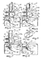
- each flattened can A arrives tangent to the magnetized cylinder 19 and, if it is made of aluminum, continues downward, since it cannot be attracted by the cylinder 19; if instead it is made of white latten, as indicated by B in figure 7, it is attracted and kept coupled to the roller until said roller, after a rotation of approximately 90°, moves the can to collide against a stop plate 21, thus forcing it to separate and fall onto an inclined plane 22 which conveys it into a second rigid container 23.
- the flattened aluminum cans are instead collected by gravity within a first rigid container 24; the two containers 23 and 24 are located within the cabinet 1.
- Figure 5 in fact illustrates an empty aluminum can A which is inserted in the loader tube 15 while the machine is running; by gravity it rests on the surface of the moving rotor 6, is then dragged by a tooth 6a against the plate 11 and then, while the tooth retracts into the rotor, said can is crushed against the contrast plate 11 as shown in figure 6; after crushing (which reduces it substantially to the shape of an elongated flat plate as indicated by A in figure 6), the can, which is made of aluminum, is not attracted by the magnetized cylinder 19 so that it continues and falls into the container 24.
- the empty can B loaded as in figure 7 is instead made of white latten, it is crushed between the rotor 6 and the plate 11 and is then attracted by the magnetized cylinder 19, as illustrated in figure 7, then dragged against the stop plate 21 (figure 8) which forces it to separate from the cylinder 19 and to then fall onto the inclined plane 22 and then into the container 23.
- the rotation rate of the rotor 6 and of the magnetized cylinder 19 is very high, so that its capacity is also high; the degree of flattening of the cans (ratio between final volume and volume before crushing) is furthermore very high and the flattened shape assumed by each can after crushing ensures a firm grip of white-latten cans on the part of the magnetized cylinder.
- the above described machine is furthermore provided with a device capable of automatically expelling from the crushing rotor 6 any solid foreign body of considerable size which, if dragged between the rotor and the contrast plate, would lead to the jamming of rotation, shorting the motor or in any case severely damaging the entire machine.
- Said device is constituted by a device (not illustrated in the figures) for reversing the direction of rotation of the motor, provided with an appropriately adjusted timer, capable of rotating the rotor 6 in a reverse direction for a preset time so as to transfer the foreign body into the region above the stop plate 21, from which it can then fall by gravity into the white-latten crushed can container, according to the path indicated by the arrow F in figure 6, or can fall laterally to the longitudinal sides of said stop plate 21. If by chance a tooth 6a, 6b, 6c or 6d remains locked in its groove, the corresponding diametrical rods 25-26 extract it when the opposite tooth retracts into its own groove against the contrast plate 11.
- a pedal which supplies power to the motor while it is kept pressed, as well as an ordinary button to be actuated manually by the user, or other optical means or the like, controlled by the passage of the cans within the loading tube 15, can be provided for starting the machine.
- Said machine can be provided with light-emitting indicators for indicating the condition of power being supplied to the motor or for other requirements.
- the crushing machine particularly for collecting cans made of aluminum or other materials, according to the invention, comprises a box-like supporting body 101 which preferably but not necessarily has the shape of a cabinet which is open upward and is frontally provided with a swinging door 102.
- Two parallel transverse bars 103a and 103b are provided above the body 101, and a body 104, constituted by four uprights to which two mutually opposite vertical containment plates 104a and 104b are connected, is fixed thereon.
- a shaft 105 with horizontal axis is mounted between the parallel plates 104a and 104b, and a rotor 106 with a contoured profile, driven by an electric motor 107 by means of pulleys 108 and 109 with related transmission belt 110, is keyed thereon.
- the rotor 106 is provided with engagement means constituted by recesses 106a and 106b (figure 19) which are defined on the cylindrical generatrix of the rotor and define two can resting planes 107a and 107b which are flanked by respective mutually parallel raised portions 108a and 108b, each of which is perpendicular to its respective can resting plane.
- Said raised portions 108a and 108b in practice provide the means which insert against the can to drag it, whereas the planes 107a and 107b in practice provide the resting of the cans which are fed by gravity.
- a contrast means advantageously constituted by a vertical contrast plate 111 which is movably mounted on four horizontal rods 112 in contrast with cylindrical return springs 113, is arranged on an open side of the body constituted by the adjacent plates 104a and 104b.
- Said rods 112 are rigidly associated with the vertical edges of the plates 104a and 104b and each has, at its free end, a nut 114 for adjusting the loading of the springs 113, which in practice defines the crushing pressure for the can.
- the plate 111 is arranged proximate to the cylindrical profile of the rotor, in practice tangent thereto, so as to leave a preset space which is suitable for crushing and allowing the passage of one can at a time.
- a tubular sleeve 115 is rigidly associated with the plate 111 by means of a vertical arm 111a and constitutes the means for loading by gravity one can at a time.
- the arrangement of the loader 115 is such that each can is able to arrive on the rotor 106, or rather on the plane 107a or 107b, so as to be guided against the plate 111.
- a shaft 116 is arranged below and laterally with respect to the crushing rotor 106 and is rotatably mounted between two opposite arms 117 which are rigidly associated with the horizontal crosspieces 103a and 103b; said shaft has an axis of rotation which is parallel to that of the shaft 105 of the rotor and a direction of rotation which is opposite to the direction of rotation of said rotor.
- the rotary motion of the shaft 116 is drawn from that of the shaft 105 by means of a transmission with gears 105a and 116a which are respectively rigidly associated with the shafts 105 and 116.
- a roller 119 is keyed on the shaft 116 and has at least regions made of permanently magnetized material which in practice provide the means for sorting the crushed cans.
- the cans make contact with the roller 119 and, if they are made of white latten, are attracted and retained by the roller 119 which drags them until they strike against a stop plate 121 which in practice separates the can from the roller 119.
- the separated can falls into a container 124 for collecting white latten cans.
- the operation of the above described crushing machine comprises an automatic sequence of operating steps which are illustrated in figures 15 to 18.
- a can C inserted in the sleeve 115, falls by gravity onto the rotor 116 and rests on said rotor until it is inserted into the resting plane 107a or 107b and thus remains engaged by one of the raised portions 108a or 108b as illustrated in figure 15.
- the rotation of the rotor 106 combined with the action of the raised portion, pushes the can against the contrast plate 111, flattening said can as illustrated in figure 16.
- the can A is made of aluminum, once it is flattened it falls against the roller 119 and is deflected onto the slide 122 which directs it toward the first container 123.
- the can is made of white latten, once crushing is complete and the can is therefore flattened, it falls against the roller 119, which in practice retains it, and is dragged to the stop plate 121 which separates the can which consequently drops into the second container 124.
- the rotation rate of the rotor 106 and therefore of the roller 119 is high, so the capacity of the machine is considerably high; the degree of crushing to which the cans are subjected, i.e. the ratio between the volume before crushing and the volume after crushing, is furthermore very high, and the flattened shape of each can after crushing facilitates excellent compaction of the product and easy grip on the part of the roller 119 if said cans are made of white latten.
- means are provided for reversing the motion of the rotor if bulky means or such means as to cause its jamming are introduced.
- the materials employed, as well as the contingent shapes and dimensions may be any according to the requirements.
Landscapes
- Engineering & Computer Science (AREA)
- Mechanical Engineering (AREA)
- Crushing And Pulverization Processes (AREA)
- Crushing And Grinding (AREA)
- Sorting Of Articles (AREA)
Applications Claiming Priority (4)
| Application Number | Priority Date | Filing Date | Title |
|---|---|---|---|
| IT8920452A IT1229702B (it) | 1989-05-11 | 1989-05-11 | Macchina schiaccialattine, barattoli e contenitori simili, con recupero separato di quelli in alluminio da quelli in banda stagnata |
| IT2045289 | 1989-05-11 | ||
| IT2253489 | 1989-11-29 | ||
| IT02253489A IT1237143B (it) | 1989-11-29 | 1989-11-29 | Macchina schiacciatrice particolarmente per il recupero di lattine in alluminio e altri materiali |
Publications (2)
| Publication Number | Publication Date |
|---|---|
| EP0397158A2 true EP0397158A2 (de) | 1990-11-14 |
| EP0397158A3 EP0397158A3 (de) | 1991-08-14 |
Family
ID=26327537
Family Applications (1)
| Application Number | Title | Priority Date | Filing Date |
|---|---|---|---|
| EP19900108791 Withdrawn EP0397158A3 (de) | 1989-05-11 | 1990-05-10 | Maschine zum Quetschen von Dosen und ähnlichen Behältern mit getrennter Sammlung derjenigen aus Aluminium und derjenigen aus Feinblech |
Country Status (1)
| Country | Link |
|---|---|
| EP (1) | EP0397158A3 (de) |
Cited By (3)
| Publication number | Priority date | Publication date | Assignee | Title |
|---|---|---|---|---|
| DE10036107C2 (de) * | 2000-07-25 | 2002-11-14 | Hans Koetterl | Vorrichtung und Verfahren zum Zusammenpressen dünnwandiger Hohlkörper aus Blech, insbesondere leerer Dosen |
| HRP20030867B1 (en) * | 2003-10-24 | 2008-12-31 | Resanović Mile | Machine for mashing cooked chestnuts |
| EP2692514A1 (de) * | 2012-07-31 | 2014-02-05 | Wincor Nixdorf International GmbH | Kompaktierungsvorrichtung zum Kompaktieren von Gebinden |
Family Cites Families (6)
| Publication number | Priority date | Publication date | Assignee | Title |
|---|---|---|---|---|
| GB416287A (en) * | 1934-04-09 | 1934-09-13 | Batchelor Robinson & Company L | A machine for use in the crushing, piercing and mixing of metallic containers, tinplates or terne or lead coated plates or strips or the like |
| US4358995A (en) * | 1980-09-02 | 1982-11-16 | Vivitar Corporation | Apparatus for crushing articles |
| US4373435A (en) * | 1981-01-05 | 1983-02-15 | Grevich John J | Crusher and separator for cans and bottles |
| US4369699A (en) * | 1981-03-09 | 1983-01-25 | Dailey Harold E | Can folding and flattening device |
| DE3536547C1 (de) * | 1985-10-12 | 1986-10-16 | Schörling GmbH & Co Waggonbau, 3000 Hannover | Überlastsicherung an einer Vorrichtung zum Zusammendrücken von Hohlkörpern, z. B. Blechbüchsen |
| JPS6381000A (ja) * | 1986-09-24 | 1988-04-11 | Kenzo Suzuki | 簡易空缶連続圧縮装置 |
-
1990
- 1990-05-10 EP EP19900108791 patent/EP0397158A3/de not_active Withdrawn
Cited By (4)
| Publication number | Priority date | Publication date | Assignee | Title |
|---|---|---|---|---|
| DE10036107C2 (de) * | 2000-07-25 | 2002-11-14 | Hans Koetterl | Vorrichtung und Verfahren zum Zusammenpressen dünnwandiger Hohlkörper aus Blech, insbesondere leerer Dosen |
| HRP20030867B1 (en) * | 2003-10-24 | 2008-12-31 | Resanović Mile | Machine for mashing cooked chestnuts |
| EP2692514A1 (de) * | 2012-07-31 | 2014-02-05 | Wincor Nixdorf International GmbH | Kompaktierungsvorrichtung zum Kompaktieren von Gebinden |
| US10195808B2 (en) | 2012-07-31 | 2019-02-05 | Wincor Nixdorf International, GmbH | Compacting apparatus for compacting receptacles |
Also Published As
| Publication number | Publication date |
|---|---|
| EP0397158A3 (de) | 1991-08-14 |
Similar Documents
| Publication | Publication Date | Title |
|---|---|---|
| DE2543692C2 (de) | Vorrichtung zur Verwendung beim Entleeren von Briefumschlägen | |
| DE2020825C3 (de) | Automatische Vorrichtung zum Zuführen von Zigaretten o.dgl. stabförmigen Gegenständen | |
| EP0312490B1 (de) | Verfahren und Vorrichtung zur Bildung und zum Transport von Gruppen flachseitig aneinander liegender Nahrungsmittelscheiben, insbesondere Biscuits | |
| DE2201103C3 (de) | Einrichtung zum Prüfen von Arzneikapseln u.dgl | |
| US4317259A (en) | Molding apparatus | |
| DE69301631T2 (de) | Verfahren und Einrichtung zur Ausgabe von Bechern in Getränkeverkaufautomaten | |
| DE2417527A1 (de) | Verfahren und vorrichtung zum zaehlen und verpacken von gegenstaenden | |
| JP2501399B2 (ja) | 整合させた食品の堆積を容器内に転送する装置 | |
| DE3113045A1 (de) | Verpackungsmaschine | |
| DE3149799A1 (de) | Vorrichtung zum flachpressen leerer dosen | |
| US3019575A (en) | Apparatus for inserting straws or the like | |
| CN112535298A (zh) | 一种拍打式板栗取出装置 | |
| EP0397158A2 (de) | Maschine zum Quetschen von Dosen und ähnlichen Behältern mit getrennter Sammlung derjenigen aus Aluminium und derjenigen aus Feinblech | |
| DE3015841A1 (de) | Stapelvorrichtung fuer flache artikel | |
| EP0167138A2 (de) | Verfahren und Vorrichtung zum Befüllen von Kartons | |
| CN104567558B (zh) | 一种烟花筒理顺与分选方法及其装置 | |
| CN221215982U (zh) | 一种香肠挂杆分杆和自动送杆装置及香肠生产线 | |
| CN216167051U (zh) | 自动包饺子机 | |
| US3488798A (en) | Patty forming apparatus | |
| DE852070C (de) | Spinn- oder Zwirnmaschine mit einer Vorrichtung zum Absetzen der vollen Garnkoerper | |
| CN110422365A (zh) | 一种卤蛋包装理料及投放机构 | |
| US2525990A (en) | Feeding and cutting means for citrus fruit juice extractors | |
| US1439536A (en) | Carton-filling machine | |
| DE1255372B (de) | Speiseeisselbstverkaeufer | |
| CN113951293B (zh) | 自动包饺子机及包饺子方法 |
Legal Events
| Date | Code | Title | Description |
|---|---|---|---|
| PUAI | Public reference made under article 153(3) epc to a published international application that has entered the european phase |
Free format text: ORIGINAL CODE: 0009012 |
|
| AK | Designated contracting states |
Kind code of ref document: A2 Designated state(s): AT BE CH DE DK ES FR GB GR IT LI LU NL SE |
|
| PUAL | Search report despatched |
Free format text: ORIGINAL CODE: 0009013 |
|
| AK | Designated contracting states |
Kind code of ref document: A3 Designated state(s): AT BE CH DE DK ES FR GB GR IT LI LU NL SE |
|
| STAA | Information on the status of an ep patent application or granted ep patent |
Free format text: STATUS: THE APPLICATION IS DEEMED TO BE WITHDRAWN |
|
| 18D | Application deemed to be withdrawn |
Effective date: 19920215 |