EP0396530B1 - Spülsystem für eine Zweitakt-Brennkraftmaschine - Google Patents
Spülsystem für eine Zweitakt-Brennkraftmaschine Download PDFInfo
- Publication number
- EP0396530B1 EP0396530B1 EP90890132A EP90890132A EP0396530B1 EP 0396530 B1 EP0396530 B1 EP 0396530B1 EP 90890132 A EP90890132 A EP 90890132A EP 90890132 A EP90890132 A EP 90890132A EP 0396530 B1 EP0396530 B1 EP 0396530B1
- Authority
- EP
- European Patent Office
- Prior art keywords
- membrane
- internal combustion
- combustion engine
- valve
- stroke internal
- Prior art date
- Legal status (The legal status is an assumption and is not a legal conclusion. Google has not performed a legal analysis and makes no representation as to the accuracy of the status listed.)
- Expired - Lifetime
Links
Images

Classifications
-
- F—MECHANICAL ENGINEERING; LIGHTING; HEATING; WEAPONS; BLASTING
- F02—COMBUSTION ENGINES; HOT-GAS OR COMBUSTION-PRODUCT ENGINE PLANTS
- F02B—INTERNAL-COMBUSTION PISTON ENGINES; COMBUSTION ENGINES IN GENERAL
- F02B25/00—Engines characterised by using fresh charge for scavenging cylinders
-
- F—MECHANICAL ENGINEERING; LIGHTING; HEATING; WEAPONS; BLASTING
- F02—COMBUSTION ENGINES; HOT-GAS OR COMBUSTION-PRODUCT ENGINE PLANTS
- F02B—INTERNAL-COMBUSTION PISTON ENGINES; COMBUSTION ENGINES IN GENERAL
- F02B75/00—Other engines
- F02B75/02—Engines characterised by their cycles, e.g. six-stroke
- F02B2075/022—Engines characterised by their cycles, e.g. six-stroke having less than six strokes per cycle
- F02B2075/025—Engines characterised by their cycles, e.g. six-stroke having less than six strokes per cycle two
-
- F—MECHANICAL ENGINEERING; LIGHTING; HEATING; WEAPONS; BLASTING
- F02—COMBUSTION ENGINES; HOT-GAS OR COMBUSTION-PRODUCT ENGINE PLANTS
- F02B—INTERNAL-COMBUSTION PISTON ENGINES; COMBUSTION ENGINES IN GENERAL
- F02B29/00—Engines characterised by provision for charging or scavenging not provided for in groups F02B25/00, F02B27/00 or F02B33/00 - F02B39/00; Details thereof
Definitions
- the invention relates to a two-stroke internal combustion engine with flushing ducts opening into the cylinder and an outlet duct, with flushing slots and outlet slit controlled by the piston of the internal combustion engine, the flushing ducts being preceded by a pressure-controlled diaphragm valve arranged in a duct section, with which the flushing flow is connected within the opening duration of the flushing slots the individual flushing slots can be interrupted.
- a two-stroke internal combustion engine of the type mentioned at the outset is known from US Pat. No. 3,815,558, in which a pressure-controlled diaphragm valve is provided in the overflow channel.
- the overflow valve opens the overflow channel at a low pressure difference and closes when the pressure is equalized.
- This type of flow control for flushing systems has the disadvantage that the opening and closing times of the diaphragm valve, apart from the pressure difference, cannot be influenced.
- the object of the invention is to improve known flushing systems for two-stroke internal combustion engines in such a way that, with reasonable constructional effort, engine operation without interruptions is ensured even in the part-load range of the internal combustion engine is, the catalytic aftertreatment of the exhaust gases should not be made more difficult.
- the scavenging control system enables the scavenging time to be controlled in a simple manner in two-stroke engines and is suitable for both engines with reverse and direct current scavenging.
- the purpose of this system is to achieve a control of the mixture quantity or fresh air quantity let into the working cylinder per cycle which is favorable for the engine operation.
- Both the crankcase pump formed by the engine piston and an external blower can serve as the purge air source.
- the decisive advantage of this flushing control system compared to the conventional throttle control is the timing of the flushing process.
- the electromagnetically unlockable membrane valve is arranged in a common feed channel to the individual flushing channels, or if, in the case of a two-stroke internal combustion engine with crankcase purge, the electromagnetically unlockable membrane valve is arranged in a common overflow channel leading from the crankcase to the cylinder.
- a particularly advantageous embodiment of the invention is characterized in that the diaphragm valve has at least one, preferably two symmetrically designed diaphragm tongues which are mounted on one side and which, in the closed state of the diaphragm valve, can be determined at their free, ferromagnetic ends by electromagnets supported on the channel section.
- the diaphragm tongue or several diaphragm tongues are either ferromagnetic in their entirety or at least at their free ends and are held in their closed position by electromagnets and thus block the flushing flow through the flushing slots, despite the pressure difference applied to the diaphragm valve when the flushing slots are open.
- the solenoids are switched off to open the diaphragm valve.
- the diaphragm openings open due to the applied pressure difference and thus release the flushing flow to the cylinder. Due to the flow resistance, the membrane openings remain open until the flushing slots are closed by the piston. After the rinsing process has ended, the flow resistance acting as the opening force ceases and the membrane perforations begin to close due to their inherent elasticity or due to spring elements acting on the membrane perforations. When the current for the electromagnets is switched on again, the diaphragm seals are held in place again in the next cycle.
- the entire purge control system can either remain without current, the position of the membrane openings being determined solely by the flow resistance, or, according to a development of the invention, at full load of the two-stroke internal combustion engine, the at least one membrane tongue in the open state of the membrane valve Electromagnets arranged on the wall of the channel section can be ascertained. This advantageously reduces the overall flow resistance of the diaphragm valve arrangement.
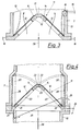
- the diaphragm valve has two symmetrically formed, preferably frame-shaped diaphragm supports, each rotatably mounted in the channel section, at the free ends of which electromagnets are arranged, with which diaphragm seals fastened on one side to the diaphragm supports can be locked in the closed position of the diaphragm valve, whereby Extensions of the channel section are provided which accommodate the two diaphragm supports together with the diaphragm tongues at full load of the two-stroke internal combustion engine, and that the two diaphragm supports can be moved by means of an actuating linkage and can be fixed in their open position at full load.
- the diaphragm tongues can be held in place by energizing the magnets, the power supply being switched off to open the diaphragm valve at part load.
- the membrane carriers are folded away or their open position is fixed via an actuating linkage, as a result of which the flow resistance is minimized.
- the membrane tongues or membrane carriers are arranged essentially roof-shaped in a channel section with a rectangular cross-section, the free ends of the membrane tongues or membrane carriers pointing in the direction of flow of the flushing stream.
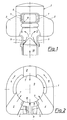
- the flushing system of a two-stroke internal combustion engine shown in FIGS. 1 and 2 has three flushing ducts 2 opening into the cylinder 1, which, starting from a common duct section 3 via duct parts 4 and 5, are supplied with fresh charge or fresh air with internal mixture formation.
- Two of the flushing channels 2 are arranged on both sides of the outlet channel 6, one of the flushing channels is arranged opposite the outlet channel 6.
- the flushing slots 7 and the outlet slot 8 are controlled by the piston 9 of the internal combustion engine.
- Both a crankcase pump formed by the engine piston (not shown here) and an external blower for the fresh air opening into the pipe socket 10 can serve as the flushing current source.
- the rigid control element of the flushing slots 7 is preceded by an electromagnetically unlockable membrane valve 11 which is arranged in the channel section 3 and which can either block or release the flushing flow within the opening period determined by the flushing slots 7.
- This intervention in the flushing control time is now expediently carried out in such a way that, with falling load, the electromagnetically unlockable membrane valve 11 opens increasingly later than the flushing slots 7 and, after the start of the flushing thus determined, remains open until after the flushing slots 7 have been closed.
- the rinsing end is thus given by the timing of the rinsing slots 7.
- the entire crank angle range is available in which the flushing slots 7 are covered by the piston 9, which allows a relatively slow closing and thus enables the use of inexpensive actuators.
- the electromagnetic diaphragm valve 11 can have two diaphragm tongues 12 which are fastened on one side in the channel section 3 and which are held by electromagnets 15 at their free, ferromagnetic ends 14 in the closed state.
- the electromagnets 15, the electrical connections of which are denoted by 16, are fastened on a carrier 17 arranged in the channel section 3.
- the diaphragm tongues 12 can also be entirely ferromagnetic and, after the flushing process has ended, they close either by their own elasticity or by spring elements, not shown here, acting on the diaphragm tongues 12.
- the diaphragm tongues 12 in the open state 13 can on the wall of the channel section 3 attached electromagnets 18 are held, which are supplied with electricity via electrical connections 19.
- the diaphragm tongues are thereby held in their largest opening position, as a result of which the overall flow resistance of the diaphragm valve 11 is reduced.
- the electromagnetically unlockable diaphragm valve 11 has two essentially symmetrically designed diaphragm supports 20, one end 21 of which is rotatably mounted in the channel section 3 and the free ends 22 of which lie close together in the illustrated, closed state of the diaphragm valve.
- membrane supports 20, which are frame-shaped here membrane tongues 12 are attached to the ends 21, the free ends 14 of which cooperate with electromagnets 23 fixed to the free ends 22 of the membrane supports 20.
- the diaphragm tongues 12 are released by the electromagnets 23, as in the embodiment according to FIG. 3, while the diaphragm supports 20 are fixed by means of an actuating linkage 24 to 27.
- the valve body consisting of the two diaphragm supports 20 and the diaphragm tongues 12 is divided symmetrically and completely folded into lateral extensions 28 of the channel section 3 via the actuating linkage 24 to 27 and fixed there. When opened, the entire channel cross-section is available for the flushing flow.
- the roof-shaped arrangement of the membrane tongues 12 or membrane carrier 20 supports their opening by the flushing flow along arrow 29.
- the purge system of a two-stroke internal combustion engine is shown in a crank angle diagram.
- the maximum exhaust opening time A and the maximum flushing channel opening time S are determined by the height of the exhaust or flushing slots in the cylinder of the internal combustion engine. These are swept by the piston and released for a certain crank angle range A or S symmetrically to the bottom dead center UT.
- the start of the purging is now delayed by the time V depending on the load or speed values, as a result of which the purging flow is interrupted in the crank angle region V and the delayed purging can only take place in the SV region.
- Point of time the opening of the diaphragm valve is shifted in direction a at higher loads and in direction b at lower loads.
Landscapes
- Engineering & Computer Science (AREA)
- Chemical & Material Sciences (AREA)
- Combustion & Propulsion (AREA)
- Mechanical Engineering (AREA)
- General Engineering & Computer Science (AREA)
- Valve Device For Special Equipments (AREA)
- Output Control And Ontrol Of Special Type Engine (AREA)
- Electrical Control Of Air Or Fuel Supplied To Internal-Combustion Engine (AREA)
Description
- Die Erfindung betrifft eine Zweitakt-Brennkraftmaschine mit in den Zylinder mündenden Spülkanälen und einem Auslaßkanal, mit vom Kolben der Brennkraftmaschine gesteuerten Spülschlitzen und Auslaßschlitz, wobei den Spülkanälen ein in einem Kanalabschnitt angeordnetes druckgesteuertes Membranventil vorgeschaltet ist, mit welchem innerhalb der Öffnungsdauer der Spülschlitze der Spülstrom zu den einzelnen Spülschlitzen unterbrechbar ist.
- Bei herkömmlichen Spülsystemen von Zweitakt-Brennkraftmaschinen ergeben sich gewisse Nachteile im Teillastbetrieb, da es zur Vermischung der in den Arbeitszylinder einströmenden Gemischmenge (bzw. Frischluftmenge bei innerer Gemischbildung) mit dem im Zylinder befindlichen Restgas kommt und sich die Gemischwolke zum Zündzeitpunkt nicht in optimaler Nähe der Zündkerze befindet. In der Folge kommt es zu unangenehmen Aussetzern im Motorbetrieb.
- Bei Zweitakt-Motoren mit innerer Gemischbildung wurden zur Erzielung eines aussetzerfreien Betriebes beispielsweise höhere Spülluftmengen bei Teillast verwendet. Nachteilig ist die dabei auftretende Rückkühlung des Abgases, wodurch die katalytische Abgasnachbehandlung verschlechtert wird.
- Aus der US-PS 3,815.558 ist eine Zweitakt-Brennkraftmaschine der eingangs erwähnten Bauart bekannt, bei der ein druckgesteuertes Membranventil im Überströmkanal vorgesehen ist. Das Überströmventil öffnet den Überströmkanal bei geringer Druckdifferenz und schließt bei Druckausgleich. Diese Art der Durchflußsteuerung für Spülsysteme hat den Nachteil, daß die Öffnungs- und Schließzeiten des Membranventils, abgesehen durch die Druckdifferenz, nicht beeinflußbar sind.
- Aufgabe der Erfindung ist es, bekannte Spülsysteme für Zweitakt-Brennkraftmaschinen derart zu verbessern, daß mit einem vertretbaren baulichen Aufwand auch im Teillastbereich der Brennkraftmaschine ein aussetzerfreier Motorbetrieb gewährleistet ist, wobei die katalytische Nachbehandlung der Abgase nicht erschwert werden soll.
- Diese Aufgabe wird erfindungsgemäß dadurch gelöst, daß das Membranventil elektromagnetisch entriegelbar ist, wodurch die Spülzeit abhängig vom Last- und Drehzahlzustand der Brennkraftmaschine steuerbar ist. Das erfindungsgemäße Spülsteuerungssystem ermöglicht bei Zweitakt-Motoren auf einfache Weise eine Steuerung der Spülzeit und ist sowohl für Motoren mit Umkehr- als auch mit Gleichstromspülung geeignet. Zweck dieses Systems ist es, eine für den Motorbetrieb günstige Steuerung der pro Zyklus in den Arbeitszylinder eingelassenen Gemischmenge bzw. Frischluftmenge zu erzielen. Als Spülluftquelle kann dabei sowohl die durch den Motorkolben gebildete Kurbelkastenpumpe, als auch ein externes Gebläse dienen. Der gegenüber der herkömmlichen Drosselregelung entscheidende Vorteil dieses Spülsteuerungssystems besteht in der zeitlichen Steuerung des Spülvorganges. Durch bei Teillast gegenüber dem Vollastspülbeginn mittels des elektromagnetisch entriegelbaren Membranventiles verzögerten Beginn des Spülvorganges ist es möglich, die eingelassene Gemischmenge in Form einer konzentrierten Wolke im Brennraum zu halten und so weitgehend die Vermischung mit dem im Zylinder befindlichen Restgas zu verhindern. Durch geeignete Brennraumform und Anordnung der Spülkanäle kann weiters erreicht werden, daß sich diese Gemischwolke zum Zündzeitpunkt an der Zündkerze befindet. Auf diese Weise kann auch bei dem bei Teillast auftretenden hohen Restgasgehalt ein aussetzerfreier Motorbetrieb gewährleistet werden, wobei auch eine Rückkühlung des Abgases verhindert wird.
- Obwohl es durchaus möglich ist, jedem der Spülkanäle ein magnetisch betätigbares Ventil vorzuschalten, ist es von Vorteil, wenn erfindungsgemäß das elektromagnetisch entriegelbare Membranventil in einem gemeinsamen Zuführkanal zu den einzelnen Spülkanälen angeordnet ist, bzw. wenn bei einer Zweitakt-Brennkraftmaschine mit Kurbelkastenspülung das elektromagnetisch entriegelbare Membranventil in einem vom Kurbelkasten zum Zylinder führenden gemeinsamen Überströmkanal angeordnet ist.
- Eine besonders vorteilhafte Ausgestaltung der Erfindung ist dadurch gekennzeichnet, daß das Membranventil zumindest eine, vorzugsweise zwei symmetrisch ausgeführte, einseitig gelagerte Membranzungen aufweist, die im geschlossenen Zustand des Membranventiles an ihren freien, ferromagnetischen Enden von am Kanalabschnitt abgestützten Elektromagneten feststellbar sind. Die Membranzunge bzw. mehrere Membranzungen sind entweder zur Gänze oder zumindest an ihren freien Enden ferromagnetisch und werden im Schließzustand durch Elektromagnete auf ihrem Sitz gehalten und sperren so - trotz der bei geöffneten Spülschlitzen am Membranventil anliegenden Druckdifferenz - den Spülstrom durch die Spülschlitze. Zum Öffnen des Membranventiles werden die Elektromagnete abgeschaltet. Die Membranzungen öffnen aufgrund der anliegenden Druckdifferenz und geben so den Spülstrom zum Zylinder frei. Durch den Strömungswiderstand bleiben die Membranzungen bis zum Schließen der Spülschlitze durch den Kolben geöffnet. Nach Beendigung des Spülvorganges fällt der als Öffnungskraft wirkende Strömungswiderstand fort und die Membranzungen beginnen durch ihre Eigenelastizität, bzw. durch an den Membranzungen angreifende Federelemente zu schließen. Durch erneutes Anschalten des Stromes für die Elektromagneten werden die Membranzungen im nächsten Zyklus wieder auf ihrem Sitz festgehalten.
- Bei Vollast der Brennkraftmaschine kann das gesamte Spülsteuerungssystem entweder stromlos bleiben, wobei die Stellung der Membranzungen damit allein durch den Strömungswiderstand bestimmt wird, oder es kann gemäß einer Weiterbildung der Erfindung bei Vollast der Zweitakt-Brennkraftmaschine, die zumindest eine Membranzunge in geöffneten Zustand des Membranventils von an der Wand des Kanalabschnittes angeordneten Elektromagneten feststellbar sein. Vorteilhafterweise wird dadurch der Gesamtströmungswiderstand der Membranventilanordnung gesenkt.
- Eine andere Ausführungsvariante der Erfindung sieht vor, daß das Membranventil zwei symmetrisch ausgebildete im Kanalabschnitt jeweils drehbar gelagerte, vorzugsweise rahmenförmige Membranträger aufweist, an deren freien Enden jeweils Elektromagnete angeordnet sind, mit welchen an den Membranträgern einseitig befestigte Membranzungen in Schließstellung des Membranventiles feststellbar sind, wobei Erweiterungen des Kanalabschnittes vorgesehen sind, welche bei Vollast der Zweitakt-Brennkraftmaschine die beiden Membranträger samt Membranzungen aufnehmen, sowie daß die beiden Membranträger mittels eines Betätigungsgestänges bewegbar und in deren Offenstellung bei Vollast fixierbar sind. Im geschlossenen Zustand des Membranventiles können dabei die Membranzungen durch Erregung der Magneten festgehalten werden, wobei zum Öffnen des Membranventiles bei Teillast die Stromzufuhr abgeschaltet wird. Über ein Betätigungsgestänge werden bei Vollast die Membranträger weggeklappt bzw. deren Offenstellung fixiert, wodurch der Strömungswiderstand minimiert wird.
- Schließlich ist erfindungsgemäß vorgesehen, daß die Membranzungen oder Membranträger in einem Kanalabschnitt mit rechtekkigem Querschnitt im wesentlichen dachförmig angeordnet sind, wobei die freien Enden der Membranzungen oder Membranträger in die Strömungsrichtung des Spülstromes zeigen.
- Die Erfindung wird im folgenden anhand von Zeichnungen näher erläutert. Es zeigen in zum Teil schematischer Darstellung:
- Fig. 1 und 2 ein erfindungsgemäßes Spülsystem einer Zweitakt-Brennkraftmaschine im Aufriß und im Grundriß,
- Fig. 3 ein elektromagnetisch entriegelbares Membranventil des Spülsystems,
- Fig. 4 eine Ausführungsvariante nach Fig. 3 und
- Fig. 5 ein Steuerdiagramm der Zweitakt-Brennkraftmaschine.
- Das in Fig. 1 und 2 dargestellte Spülsystem einer Zweitakt-Brennkraftmaschine weist drei in den Zylinder 1 mündende Spülkanäle 2 auf, welche ausgehend von einem gemeinsamen Kanalabschnitt 3 über Kanalteile 4 und 5 mit Frischladung, bzw. Frischluft bei innerer Gemischbildung, versorgt werden.
- Zwei der Spülkanäle 2 sind zu beiden Seiten des Auslaßkanales 6 angeordnet, einer der Spülkanäle ist dem Auslaßkanal 6 gegenüberliegend angeordnet. Die Spülschlitze 7 bzw. der Auslaßschlitz 8 werden vom Kolben 9 der Brennkraftmaschine gesteuert. Als Spülstromquelle kann sowohl eine durch den Motorkolben gebildete, hier nicht weiter dargestellte Kurbelkastenpumpe, als auch ein in den Rohrstutzen 10 mündendes externes Gebläse für die Frischluft dienen.
- Dem starren Steuerorgan der Spülschlitze 7 wird ein im Kanalabschnitt 3 angeordnetes, elektromagnetisch entriegelbares Membranventil 11 vorgeschaltet, das innerhalb der von den Spülschlitzen 7 bestimmten Öffnungsdauer den Spülstrom entweder sperren oder freigeben kann. Dieser Eingriff in die Spülsteuerzeit wird nun zweckmäßig so vorgenommen, daß mit sinkender Last das elektromagnetisch entriegelbare Membranventil 11 zunehmend später öffnet als die Spülschlitze 7 und nach dem so bestimmten Spülbeginn bis nach dem Schließen der Spülschlitze 7 geöffnet bleibt. Das Spülende ist somit durch die Steuerzeit der Spülschlitze 7 gegeben. Für das abermalige Schließen des Membranventiles 11 steht jedoch der gesamte Kurbelwinkelbereich zur Verfügung in dem die Spülschlitze 7 vom Kolben 9 verdeckt sind, was ein verhältnismäßig langsames Schließen zuläßt und damit die Verwendung kostengünstiger Betätigungsorgane ermöglicht.
- Wie in Fig. 3 dargestellt, kann das elektromagnetische Membranventil 11 zwei im Kanalabschnitt 3 einseitig befestigte Membranzungen 12 aufweisen, welche im geschlossenen Zustand an ihren freien, ferromagnetischen Enden 14 von Elektromagneten 15 festgehalten werden. Die Elektromagnete 15, deren elektrische Anschlüsse mit 16 bezeichnet sind, sind auf einem im Kanalabschnitt 3 angeordneten Träger 17 befestigt.
- Die Membranzungen 12 können auch zur Gänze ferromagnetisch ausgebildet sein und schließen nach Beendigung des Spülvorganges entweder durch ihre Eigenelastizität oder durch an den Membranzungen 12 angreifende, hier nicht dargestellte Federelemente.
- Bei Vollast der Brennkraftmaschine können die Membranzungen 12 im geöffneten Zustand 13 von an der Wand des Kanalabschnittes 3 befestigten Elektromagneten 18 festgehalten werden, welche über elektrische Anschlüsse 19 mit Strom versorgt werden. Die Membranzungen werden dadurch in ihrer größten Öffnungstellung festgehalten, wodurch der Gesamtströmungswiderstand des Membranventiles 11 gesenkt wird.
- In der Ausführung nach Fig. 4 weist das elektromagnetisch entriegelbare Membranventil 11 zwei im wesentlichen symmetrisch ausgebildete Membranträger 20 auf, deren ein Ende 21 im Kanalabschnitt 3 jeweils drehbar gelagert ist und deren freien Enden 22 im dargestellten, geschlossenen Zustand des Membranventiles dicht aneinanderliegen. Auf den Membranträgern 20, die hier rahmenförmig ausgebildet sind, sind jeweils an den Enden 21 Membranzungen 12 befestigt, deren freie Enden 14 mit an den freien Enden 22 der Membranträger 20 fixierten Elektromagneten 23 zusammenwirken.
- Bei Teillast werden wie in der Ausführung nach Fig. 3 die Membranzungen 12 von den Elektromagneten 23 freigegeben, während die Membranträger 20 mittels eines Betätigungsgestänges 24 bis 27 fixiert werden. Bei Vollast wird der aus den beiden Membranträgern 20 und den Membranzungen 12 bestehende Ventilkörper symmetrisch geteilt und über das Betätigungsgestänge 24 bis 27 zur Gänze in seitliche Erweiterungen 28 des Kanalabschnittes 3 geklappt und dort fixiert. Im aufgeklappten Zustand steht somit für den Spülstrom der gesamte Kanalquerschnitt zur Verfügung. Durch die dachförmige Anordnung der Membranzungen 12 bzw. Membranträger 20 wird deren Öffnen durch den Spülstrom entlang Pfeil 29 unterstützt.
- In Fig. 5 ist in einem Kurbelwinkeldiagramm das gegenständliche Spülsystem einer Zweitakt-Brennkraftmaschine dargestellt. Die maximale Auspufföffnungszeit A und die maximale Spülkanalöffnungszeit S wird durch die Höhe der Auslaß- bzw. Spülschlitze im Zylinder der Brennkraftmaschine bestimmt. Diese werden vom Kolben überstrichen und jeweils für einen bestimmten Kurbelwinkelbereich A bzw. S symmetrisch zum unteren Totpunkt UT freigegeben. Mit Hilfe des gegenständlichen Steuersystems wird nun der Beginn der Spülung abhängig von Last- bzw. Drehzahlwerten um die Zeit V verzögert, wodurch der Spülstrom im Kurbelwinkelbereich V unterbrochen ist und die verzögerte Spülung nur im Bereich SV stattfinden kann. Der Zeitpunkt des Öffnens des Membranventiles wird bei höheren Lasten in Richtung a, bei niedrigeren Lasten in Richtung b verschoben.
Claims (7)
- Zweitakt-Brennkraftmaschine mit in den Zylinder mündenden Spülkanälen und einem Auslaßkanal, mit vom Kolben der Brennkraftmaschine gesteuerten Spülschlitzen (7) und Auslaßschlitz (8), wobei den Spülkanälen (2) ein in einem Kanalabschnitt (3) angeordnetes druckgesteuertes Membranventil (11) vorgeschaltet ist, mit welchem innerhalb der Öffnungsdauer der Spülschlitze (7) der Spülstrom zu den einzelnen Spülschlitzen (7) unterbrechbar ist, dadurch gekennzeichnet , daß das Ventil elektromagnetisch entriegelbar ist, wodurch die Spülzeit abhängig vom Last und Drehzahlzustand der Brennkraftmaschine steuerbar ist.
- Zweitakt-Brennkraftmaschine nach Anspruch 1, dadurch gekennzeichnet, daß das elektromagnetisch entriegelbare Membranventil (11) in einem gemeinsamen Zuführkanal zu den einzelnen Spülkanälen (2) angeordnet ist.
- Zweitakt-Brennkraftmaschine nach Anspruch 1 oder 2 mit Kurbelkastenspülung, dadurch gekennzeichnet, daß das elektromagnetisch entriegelbare Membranventil (11) in einem vom Kurbelkasten zum Zylinder (1) führenden gemeinsamen Überströmkanal angeordnet ist.
- Zweitakt-Brennkraftmaschine nach einem der Ansprüche 1 bis 3, dadurch gekennzeichnet, daß das Membranventil (11) zumindest eine, vorzugsweise zwei symmetrisch ausgeführte, einseitig gelagerte Membranzungen (12) aufweist, die im geschlossenen Zustand des Membranventiles (11) an ihren freien, ferromagnetischen Enden (14) von am Kanalabschnitt (3) abgestützten Elektromagneten (15) feststellbar sind. (Fig. 3)
- Zweitakt-Brennkraftmaschine nach Anspruch 4, dadurch gekennzeichnet, daß bei Vollast der Brennkraftmaschine die zumindest eine Membranzunge (12) im geöffneten Zustand (13) des Membranventiles (11) von an der Wand des Kanalabschnittes (3) angeordneten Elektromagneten (18) feststellbar ist. (Fig. 3)
- Zweitakt-Brennkraftmaschine nach einem der Ansprüche 1 bis 3, dadurch gekennzeichnet, daß das Membranventil (11) zwei symmetrisch ausgebildete im Kanalabschnitt (3) jeweils drehbar gelagerte, vorzugsweise rahmenförmige Membranträger (20) aufweist, an deren freien Enden (22) jeweils Elektromagnete (23) angeordnet sind, mit welchen an den Membranträgern (20) einseitig befestigte Membranzungen (12) in Schließstellung des Membranventiles (11) feststellbar sind, wobei Erweiterungen (28) des Kanalabschnittes (3) vorgesehen sind, welche bei Vollast der Zweitakt-Brennkraftmaschine die beiden Membranträger (20) samt Membranzungen (12) aufnehmen, sowie daß die beiden Membranträger (20) mittels eines Betätigungsgestänges (24-27) bewegbar und in deren Offenstellung bei Vollast fixierbar sind. (Fig. 4)
- Zweitakt-Brennkraftmaschine nach einem der Ansprüche 4 bis 6, dadurch gekennzeichnet, daß die Membranzungen (12) oder Membranträger (20) in einem Kanalabschnitt (3) mit rechteckigem querschnitt im wesentlichen dachförmig angeordnet sind, wobei die freien Enden (14, 22) der Membranzungen (12) oder Membranträger (20) in die Strömungsrichtung (29) des Spülstromes zeigen.
Applications Claiming Priority (2)
| Application Number | Priority Date | Filing Date | Title |
|---|---|---|---|
| AT0104889A AT407426B (de) | 1989-05-02 | 1989-05-02 | Spülsystem für eine zweitakt-brennkraftmaschine |
| AT1048/89 | 1989-05-02 |
Publications (2)
| Publication Number | Publication Date |
|---|---|
| EP0396530A1 EP0396530A1 (de) | 1990-11-07 |
| EP0396530B1 true EP0396530B1 (de) | 1992-10-28 |
Family
ID=3505468
Family Applications (1)
| Application Number | Title | Priority Date | Filing Date |
|---|---|---|---|
| EP90890132A Expired - Lifetime EP0396530B1 (de) | 1989-05-02 | 1990-04-30 | Spülsystem für eine Zweitakt-Brennkraftmaschine |
Country Status (5)
| Country | Link |
|---|---|
| US (1) | US5033419A (de) |
| EP (1) | EP0396530B1 (de) |
| AT (1) | AT407426B (de) |
| DE (1) | DE59000393D1 (de) |
| ES (1) | ES2035743T3 (de) |
Families Citing this family (8)
| Publication number | Priority date | Publication date | Assignee | Title |
|---|---|---|---|---|
| SE467268B (sv) * | 1990-05-30 | 1992-06-22 | Volvo Ab | Foerbraenningsmotor med troeghetsuppladdning |
| JPH0617659A (ja) * | 1992-07-06 | 1994-01-25 | Yamaha Motor Co Ltd | エンジンの吸気用逆止弁 |
| IT1278827B1 (it) * | 1995-04-28 | 1997-11-28 | Monika Paszkowska | Valvola termodinamica ad aspirazione |
| DE19908435A1 (de) * | 1999-02-26 | 2000-09-07 | Meta Motoren Energietech | Verfahren und Vorrichtung zur Impulsaufladung einer Kolbenbrennkraftmaschine |
| JP2013024137A (ja) * | 2011-07-21 | 2013-02-04 | Hitachi Koki Co Ltd | エンジン及びエンジン作業機 |
| DE102015203788B4 (de) * | 2015-03-03 | 2020-02-27 | Ford Global Technologies, Llc | Brennkraftmaschine mit Vorrichtung zur Impulsaufladung und Verfahren zum Betreiben einer derartigen Brennkraftmaschine |
| CN105200373A (zh) * | 2015-09-14 | 2015-12-30 | 京东方科技集团股份有限公司 | 用于有机发光二极管蒸镀系统中的填料装置及方法 |
| DE102018003476A1 (de) | 2018-04-24 | 2019-10-24 | Andreas Stihl Ag & Co. Kg | Verbrennungsmotor und Verfahren zu dessen Betrieb |
Family Cites Families (17)
| Publication number | Priority date | Publication date | Assignee | Title |
|---|---|---|---|---|
| US1366319A (en) * | 1920-03-19 | 1921-01-18 | William L Kann | Internal-combustion engine |
| GB359553A (en) * | 1929-07-29 | 1931-10-26 | Charles Gordon Curtis | Improvements in or relating to the cylinders of two-stroke-cycle internal-combustion engines |
| GB402333A (en) * | 1932-05-12 | 1933-11-30 | Sulzer Ag | Improvements in or relating to two-stroke internal combustion engines |
| US3269689A (en) * | 1964-07-01 | 1966-08-30 | Major Control Co | Electro-magnetic diaphragm valve |
| US3370305A (en) * | 1965-05-28 | 1968-02-27 | Goott Bernard | Heart valve with magnetic hinge means |
| US3815558A (en) * | 1972-08-07 | 1974-06-11 | W Tenney | Scavenge porting system |
| JPS52121820A (en) * | 1976-04-06 | 1977-10-13 | Toyota Motor Co Ltd | Reed valve |
| DE2936043C2 (de) * | 1979-09-06 | 1982-12-16 | Toyota Jidosha Kogyo K.K., Toyota, Aichi | Zweitakt-Benzinmotor |
| US4388895A (en) * | 1980-03-24 | 1983-06-21 | Performance Industries, Inc. | Fuel porting for two cycle internal combustion engine |
| US4383641A (en) * | 1980-05-12 | 1983-05-17 | Shreve James S | Electrically-controlled damper |
| AT380538B (de) * | 1980-12-18 | 1986-06-10 | Bombardier Rotax Gmbh | Vorrichtung zur steuerung der auslasszeit von zweitakt-brennkraftmaschinen |
| US4585209A (en) * | 1983-10-27 | 1986-04-29 | Harry E. Aine | Miniature valve and method of making same |
| CH664806A5 (fr) * | 1985-07-01 | 1988-03-31 | Marius Thiebaud | Soupape automatique de regulation du debit d'air soutire d'un local par une installation de ventilation mecanique. |
| JPH079179B2 (ja) * | 1986-09-24 | 1995-02-01 | スズキ株式会社 | 2サイクルエンジンのリ−ドバルブ装置 |
| DE3741880A1 (de) * | 1986-12-19 | 1988-07-28 | Volkswagen Ag | Vorrichtung zur verhinderung von frischgas-rueckstroemungen im saugrohr einer brennkraftmaschine |
| US4879976A (en) * | 1987-09-09 | 1989-11-14 | Performance Industries, Inc. | Reed valve mechanism for engines |
| DE3737828A1 (de) * | 1987-11-06 | 1989-05-18 | Schatz Oskar | Verbrennungsmotor der kolbenbauart |
-
1989
- 1989-05-02 AT AT0104889A patent/AT407426B/de not_active IP Right Cessation
-
1990
- 1990-04-30 DE DE9090890132T patent/DE59000393D1/de not_active Expired - Lifetime
- 1990-04-30 US US07/516,765 patent/US5033419A/en not_active Expired - Fee Related
- 1990-04-30 EP EP90890132A patent/EP0396530B1/de not_active Expired - Lifetime
- 1990-04-30 ES ES199090890132T patent/ES2035743T3/es not_active Expired - Lifetime
Also Published As
| Publication number | Publication date |
|---|---|
| US5033419A (en) | 1991-07-23 |
| EP0396530A1 (de) | 1990-11-07 |
| ATA104889A (de) | 2000-07-15 |
| DE59000393D1 (de) | 1992-12-03 |
| AT407426B (de) | 2001-03-26 |
| ES2035743T3 (es) | 1993-04-16 |
Similar Documents
| Publication | Publication Date | Title |
|---|---|---|
| DE3828742C3 (de) | Brennkraftmaschine mit mehreren Einlaßventilen und Abgasrückführung | |
| DE2803533A1 (de) | Luftverdichtende, selbstzuendende brennkraftmaschine | |
| AT402326B (de) | Zylinderkopf für eine brennkraftmaschine | |
| DE3930243A1 (de) | Brennkraftmaschine | |
| DE19622891C2 (de) | Abgasrückführungssystem | |
| DE3508763A1 (de) | Brennkraftmaschine mit mehreren einlassventilen | |
| DE3212910C2 (de) | ||
| DE3514327A1 (de) | Einlasssystem fuer eine verbrennungskraftmaschine mit mehreren einlassventilen | |
| DE4108469A1 (de) | Einlassvorrichtung fuer einen mehrventilmotor | |
| DD144941A1 (de) | Verbrennungskraftmotor | |
| DE19934509A1 (de) | Verbrennungsmotor mit einem Einlaßsystem mit aerodynamischem Ladungsbewegungssteuerventil | |
| EP0396530B1 (de) | Spülsystem für eine Zweitakt-Brennkraftmaschine | |
| DE3347847C2 (de) | ||
| DE10110986A1 (de) | Viertakt-Brennkraftmaschine mit zumindest zwei Einlassventilen | |
| DE3040472C2 (de) | Brennkraftmaschine | |
| DE3909544C2 (de) | ||
| EP0949414B1 (de) | Luftansaugkanalsystem für eine Brennkraftmaschine | |
| DE3923924C2 (de) | Steuervorrichtung für das Saugrohrsystem einer Fahrzeugbrennkraftmaschine | |
| DE2634334A1 (de) | Brennkraftmaschine | |
| DE3137471C2 (de) | ||
| DE7540641U (de) | Rotationskolbenmotor | |
| DE60120604T2 (de) | Verfahren zur Steuerung einer Brennkraftmaschine zur Durchführung einer homogenen Verbrennung | |
| EP1134403B1 (de) | Brennkraftmaschine mit Abgasrückführung | |
| DE2558414C2 (de) | Verbrennungskraftmaschine mit einer Steueranlage für die Abgasemission | |
| EP0373145A1 (de) | Brennkraftmaschine mit je zwei Einlassventilen pro Zylinder |
Legal Events
| Date | Code | Title | Description |
|---|---|---|---|
| PUAI | Public reference made under article 153(3) epc to a published international application that has entered the european phase |
Free format text: ORIGINAL CODE: 0009012 |
|
| AK | Designated contracting states |
Kind code of ref document: A1 Designated state(s): DE ES FR GB IT SE |
|
| 17P | Request for examination filed |
Effective date: 19901121 |
|
| 17Q | First examination report despatched |
Effective date: 19920206 |
|
| GRAA | (expected) grant |
Free format text: ORIGINAL CODE: 0009210 |
|
| AK | Designated contracting states |
Kind code of ref document: B1 Designated state(s): DE ES FR GB IT SE |
|
| GBT | Gb: translation of ep patent filed (gb section 77(6)(a)/1977) | ||
| REF | Corresponds to: |
Ref document number: 59000393 Country of ref document: DE Date of ref document: 19921203 |
|
| ET | Fr: translation filed | ||
| ITF | It: translation for a ep patent filed |
Owner name: MODIANO & ASSOCIATI S.R.L. |
|
| REG | Reference to a national code |
Ref country code: ES Ref legal event code: FG2A Ref document number: 2035743 Country of ref document: ES Kind code of ref document: T3 |
|
| PG25 | Lapsed in a contracting state [announced via postgrant information from national office to epo] |
Ref country code: SE Effective date: 19930501 |
|
| PG25 | Lapsed in a contracting state [announced via postgrant information from national office to epo] |
Ref country code: ES Free format text: LAPSE BECAUSE OF NON-PAYMENT OF DUE FEES Effective date: 19930503 |
|
| PLBE | No opposition filed within time limit |
Free format text: ORIGINAL CODE: 0009261 |
|
| STAA | Information on the status of an ep patent application or granted ep patent |
Free format text: STATUS: NO OPPOSITION FILED WITHIN TIME LIMIT |
|
| 26N | No opposition filed | ||
| PG25 | Lapsed in a contracting state [announced via postgrant information from national office to epo] |
Ref country code: FR Effective date: 19931229 |
|
| REG | Reference to a national code |
Ref country code: FR Ref legal event code: ST |
|
| PG25 | Lapsed in a contracting state [announced via postgrant information from national office to epo] |
Ref country code: GB Effective date: 19940430 |
|
| GBPC | Gb: european patent ceased through non-payment of renewal fee |
Effective date: 19940430 |
|
| EUG | Se: european patent has lapsed |
Ref document number: 90890132.5 Effective date: 19931210 |
|
| REG | Reference to a national code |
Ref country code: ES Ref legal event code: FD2A Effective date: 19990405 |
|
| PGFP | Annual fee paid to national office [announced via postgrant information from national office to epo] |
Ref country code: DE Payment date: 19991008 Year of fee payment: 10 |
|
| PG25 | Lapsed in a contracting state [announced via postgrant information from national office to epo] |
Ref country code: DE Free format text: LAPSE BECAUSE OF NON-PAYMENT OF DUE FEES Effective date: 20010201 |
|
| PG25 | Lapsed in a contracting state [announced via postgrant information from national office to epo] |
Ref country code: IT Free format text: LAPSE BECAUSE OF NON-PAYMENT OF DUE FEES;WARNING: LAPSES OF ITALIAN PATENTS WITH EFFECTIVE DATE BEFORE 2007 MAY HAVE OCCURRED AT ANY TIME BEFORE 2007. THE CORRECT EFFECTIVE DATE MAY BE DIFFERENT FROM THE ONE RECORDED. Effective date: 20050430 |