EP0396368A2 - Gegenständlich adaptiertes Bildkodiersystem - Google Patents
Gegenständlich adaptiertes Bildkodiersystem Download PDFInfo
- Publication number
- EP0396368A2 EP0396368A2 EP90304677A EP90304677A EP0396368A2 EP 0396368 A2 EP0396368 A2 EP 0396368A2 EP 90304677 A EP90304677 A EP 90304677A EP 90304677 A EP90304677 A EP 90304677A EP 0396368 A2 EP0396368 A2 EP 0396368A2
- Authority
- EP
- European Patent Office
- Prior art keywords
- sub
- band
- information
- encoding
- bands
- Prior art date
- Legal status (The legal status is an assumption and is not a legal conclusion. Google has not performed a legal analysis and makes no representation as to the accuracy of the status listed.)
- Granted
Links
Images

Classifications
-
- H—ELECTRICITY
- H04—ELECTRIC COMMUNICATION TECHNIQUE
- H04N—PICTORIAL COMMUNICATION, e.g. TELEVISION
- H04N19/00—Methods or arrangements for coding, decoding, compressing or decompressing digital video signals
- H04N19/10—Methods or arrangements for coding, decoding, compressing or decompressing digital video signals using adaptive coding
- H04N19/102—Methods or arrangements for coding, decoding, compressing or decompressing digital video signals using adaptive coding characterised by the element, parameter or selection affected or controlled by the adaptive coding
- H04N19/124—Quantisation
-
- H—ELECTRICITY
- H04—ELECTRIC COMMUNICATION TECHNIQUE
- H04N—PICTORIAL COMMUNICATION, e.g. TELEVISION
- H04N1/00—Scanning, transmission or reproduction of documents or the like, e.g. facsimile transmission; Details thereof
- H04N1/41—Bandwidth or redundancy reduction
- H04N1/4105—Bandwidth or redundancy reduction for halftone screened pictures
-
- H—ELECTRICITY
- H04—ELECTRIC COMMUNICATION TECHNIQUE
- H04N—PICTORIAL COMMUNICATION, e.g. TELEVISION
- H04N19/00—Methods or arrangements for coding, decoding, compressing or decompressing digital video signals
- H04N19/60—Methods or arrangements for coding, decoding, compressing or decompressing digital video signals using transform coding
- H04N19/61—Methods or arrangements for coding, decoding, compressing or decompressing digital video signals using transform coding in combination with predictive coding
-
- H—ELECTRICITY
- H04—ELECTRIC COMMUNICATION TECHNIQUE
- H04N—PICTORIAL COMMUNICATION, e.g. TELEVISION
- H04N19/00—Methods or arrangements for coding, decoding, compressing or decompressing digital video signals
- H04N19/60—Methods or arrangements for coding, decoding, compressing or decompressing digital video signals using transform coding
- H04N19/63—Methods or arrangements for coding, decoding, compressing or decompressing digital video signals using transform coding using sub-band based transform, e.g. wavelets
-
- H—ELECTRICITY
- H04—ELECTRIC COMMUNICATION TECHNIQUE
- H04N—PICTORIAL COMMUNICATION, e.g. TELEVISION
- H04N19/00—Methods or arrangements for coding, decoding, compressing or decompressing digital video signals
- H04N19/90—Methods or arrangements for coding, decoding, compressing or decompressing digital video signals using coding techniques not provided for in groups H04N19/10-H04N19/85, e.g. fractals
- H04N19/94—Vector quantisation
-
- H—ELECTRICITY
- H04—ELECTRIC COMMUNICATION TECHNIQUE
- H04N—PICTORIAL COMMUNICATION, e.g. TELEVISION
- H04N5/00—Details of television systems
- H04N5/76—Television signal recording
- H04N5/91—Television signal processing therefor
- H04N5/92—Transformation of the television signal for recording, e.g. modulation, frequency changing; Inverse transformation for playback
- H04N5/926—Transformation of the television signal for recording, e.g. modulation, frequency changing; Inverse transformation for playback by pulse code modulation
- H04N5/9261—Transformation of the television signal for recording, e.g. modulation, frequency changing; Inverse transformation for playback by pulse code modulation involving data reduction
-
- H—ELECTRICITY
- H04—ELECTRIC COMMUNICATION TECHNIQUE
- H04N—PICTORIAL COMMUNICATION, e.g. TELEVISION
- H04N19/00—Methods or arrangements for coding, decoding, compressing or decompressing digital video signals
- H04N19/10—Methods or arrangements for coding, decoding, compressing or decompressing digital video signals using adaptive coding
- H04N19/102—Methods or arrangements for coding, decoding, compressing or decompressing digital video signals using adaptive coding characterised by the element, parameter or selection affected or controlled by the adaptive coding
- H04N19/13—Adaptive entropy coding, e.g. adaptive variable length coding [AVLC] or context adaptive binary arithmetic coding [CABAC]
-
- H—ELECTRICITY
- H04—ELECTRIC COMMUNICATION TECHNIQUE
- H04N—PICTORIAL COMMUNICATION, e.g. TELEVISION
- H04N5/00—Details of television systems
- H04N5/76—Television signal recording
- H04N5/84—Television signal recording using optical recording
- H04N5/85—Television signal recording using optical recording on discs or drums
Definitions
- This invention relates to image processing and more particularly to encoding of images for the efficient transmission and/or storage of high quality image information.
- DPCM Pulse Code Modulation
- bit-plane coding were among the early methods used, and they achieved compression factors of up to 4-6 by trading image quality for lower bit rate.
- Pictures with higher quality than obtainable with DPCM, coded with only one bit per pixel, can now be obtained with a number of methods, such as the Adaptive Discrete Cosine Transform described by W. H. Chen and C. H. Smith, in "Adaptive Coding of Monochrome and Color Images", IEEE Trans. Comm., Vol. COM-25, pp. 1285-1292, November 1987.
- the image is decomposed into blocks, generally eight by eight, and for each of the blocks a DCT (Discrete Cosine Transform) is carried out.
- the compression is obtained by quantization of the DCT coefficients with variable thresholds, partially optimized for the human visual acumen, followed by variable word length encoding.
- Sub-band coding of images has been introduced to picture coding.
- One arrangement was proposed by J. W. Woods and S. D. O'Neil, in "Sub-Band Coding of Images", IEEE ASSP, Vol. 34 No. 5, Oct. 1986, pp. 1278-1288.
- the arrangement proposed by Woods et al includes a filter bank, that divides the image signal into bands of different frequency content, and the signal of each filter output is compressed via DPCM.
- the compressed signals are then transmitted to a receiver where the process is reversed. Specifically, each signal is DPCM decoded and then up-sampled, filtered, and combined with the other filtered signals to recover the original image.
- a sub-band analysis method for electronic image processing includes determining the amount of quantizing noise which would be just imperceptible in respect to one or more of the parameters of frequency, contrast and texture, and adapting the quantization of each pixel in response to such one or more parameters so that the amount of quantizing noise is relatively near, but below, the limit of perceptibility.
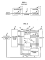
- FIG. 1 illustrates the basic communication system for practicing our invention. It includes a transmitter 11 including an encoder 12 connected, via a transmission channel 15, to a receiver 13 including a decoder 14.
- Transmission channel 15 should be considered in its broadest sense to include a storage medium, such as a compact disk read-only memory (CD ROM) or digital tape medium. That is, rather than sending encoded signals to a receiver in "real time,” one can store the signals in such a "channel” and reproduce them at a latter time upon request.
- This concept encompasses, of course, situations that are not usually thought of as communicating, the channel or "medium” being a purchased recording and the transmitter and receiver serving recording and reproduction functions of interest to a consumer, even for use in his home.
- Another major application includes archival of major collections of photographs, as in geological surveying. The "channel" 15 is then the archive.
- FIG. 2 depicts a block diagram of encoder 12. It includes an analysis filter bank 22 to which the image signal is applied.
- the image signal can have any number of formats, and the standard raster format for two dimensional images is an acceptable one. For digital filtering, the signal already has been pre-sampled (by means not shown). In addition, the signal mean value has been removed by processor 21. It is quantized to 8 bits and presented to the Perceptual Model (28) and the multiplexer (30).
- filter bank 22 has 16 outputs, from (0, 0) to (3, 3), but it is understood that this can be any number greater than 1. These correspond to the 16 possible signals of an image that was filtered into a high band and a low band and two intermediate bands in both the horizontal dimension and the vertical dimension.
- FIG. 2 includes a coder 24 that is responsive to the lowest band (0,0) image for both directions.
- the quantizer-encoder apparatus 25 in coder 24 responds to the human visual system adaptation signal on lead 26 to render the quantizing and encoding process responsive to the perceptual analysis occurring in perceptual model 28.
- the quantizer-encoder 25 is followed by a Huffman encoder 27 to prepare the signal for multiplexer 30.
- One of the inputs to model 28 is derived from processor 21 in order to provide one datum for each pixel related to contrast and brightness.
- the other inputs to perceptual model 28 are exactly the inputs to coder 24 and the other 15 similar coders.
- coder 29 and coder 31 are organized similarly to the organization of coder 24.
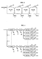
- GQMF Generalized Quadrature Mirror Filters
- the output of filters 40-43 can be down-sampled (sometimes called “subsampled”); and, to that end, down-sampling switches 45-48 are to be responsive to filters 40-43, respectively. Down-sampling can be accomplished, for example, by ignoring three out of every four samples (while, on the other hand, up-sampling would be accomplished by repeating a given sample).
- the outputs of down-sampling switches 45-48 are applied to transpose memories 50-53, respectively, that transpose the pixel signals of the two-dimensional image in the manner of transposing matrices.
- Transpose memories 50-53 are conventional memories in which signals are stored in one way (following rows) but accessed in a different way (following columns).
- transposition one may use an address counter and a memory responsive thereto, with a logic circuit interposed therebetween.
- the logic circuit allows for interchange of a number of least significant bits of of the counter with higher significant bits of the counter. A normal sequence is thus obtained without the interchange of bits; and the transposed sequence is obtained by interchanging the bits.
- transpose memory 50 is applied to filters 55-58, and similarly the outputs of transpose memories 51-53 are respectively applied to sets of filters 60-63, 65-68, (not shown) and 70-73.
- These sets of filters, for example, 55-58, are exactly like filters 40-43, in the same order and, in fact, may be implemented on a time-shared basis by the same set of digital filters.
- the outputs of filters 55-73 are applied to down-sampling switches 75-93, respectively (each numbered 20 digits higher than its corresponding filter), which produces the outputs of analysis filter bank 22.
- the GQMF filters we used split both the horizontal and vertical dimensions into four equal width bands. This number of bands provides a convenient tradeoff between spatial and frequency localization, as fewer bands would provide too coarse frequency analysis, while more bands would blur spatial localization.
- the lowest frequency in both dimensions is in sub-band (0,0), while the highest frequencies in both dimensions are in band (3,3).
- the GQMF filter that was used in our system has a first sidelobe suppression of >48dB, which ensures perfect reconstruction of an 8 bit/pixel image.
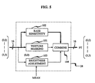
- the perceptual masking model (28) provides an estimate of the amount of coding distortion that may be added to each pixel in each sub-band signal so that there will be no discernible difference between the original image and the coded version.
- This model utilizes several well known properties of the human visual system (HVS) in unique ways. The properties we use are: frequency response; contrast sensitivity; and texture masking. This model is not meant to be a complete description of the HVS, but it provides an approximation of the effects major HVS properties have on the perception of an image given a particular analysis/synthesis procedure.
- the frequency response component (102) provides the maximum amount of distortion that can be added to each of the sub-band signals given a mid-grey flat-field image as input.
- the HVS is most sensitive to noise is this type of stimulus.
- the other components of the model adjust this distortion estimate for deviations in the image's brightness from mid-grey (block 103), and for its deviations from flat-field (block 101). These estimates are then combined (block 104), and presented as input to each of the sub-band encoders (24).
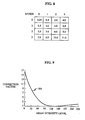
- the base sensitivity estimates were derived from a set of psychophysical experiments. A uniform mid-grey image was presented to the analysis filter bank (22). For one of the resulting sub-band signals, say (0,0), white, uniform random noise was added. This distorted signal, along with the other 15 undistorted signals were presented to the reconstruction filter bank (150). This distorted image, and the original were viewed side by side in a darkened room at a viewing distance of 6 times image height. The variance of the added white noise was adjusted to find the maximum value for which a human observer could perceive no difference between the original and distorted images. This process was then repeated for each sub-band signal in turn. Typical RMS noise sensitivity values for this experiment are presented in Figure 8. These values were experimentally derived and are dependent on the particular filters used in the analysis filter bank, and the viewing distance, therefore some variation in these values should be expected.
- the final component of the perceptual metric provides an adjustment for the decreased noise visibility given non-flat-field inputs, i.e texture.
- Flat-field stimuli have only DC frequency components, while textured input has both DC and AC components.
- the noise visibility for the DC component is accounted for by the base sensitivity and brightness adjustment terms, while the texture masking term (101) handles the AC terms.
- This texture masking term consists of a weighted sum of the AC portion of the energy in each subband. Since the HVS has a non-uniform transfer function, the energy in each subband is weighted by the relative visibility of the frequencies contained in each subband.
- a value for the perceptual metric is determined at every point in every sub-band.
- One possible implementation could use table lookup indexed by sub-band number to determine the base sensitivities, and table lookup indexed by the sum of the overall image mean and the local value from each point in sub-band (0,0) to determine the Brightness Adjustment.
- the texture masking term could be computed by taking the variance over a 2x2 pixel block in sub-band (0,0) (This computes the AC energy in the lowest frequency sub-band) weighted by the average HVS response in band (0,0). For each of the other sub-bands, added to this term would be the average energy over a 2x2 pixel block weighted by the average HVS response for that sub-band.
- This composite term would then be raised to the power 0.065. This number was set to ensure that highly textured images would be transparently coded. Each of these terms are input to the combination block (104) where they are multiplied together to produce the final value for the perceptual metric. This procedure will provide a metric that will produce visually transparent coding. If some perceptible distortion is allowable, this metric could be relaxed multiplying it by a constant > 1.0.
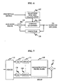
- the perceptual metric is then used to control a DPCM encoder (25) ( Figure 2) for each sub-band.
- DPCM coding is well known in the prior art.
- the predictor block (108) uses a three point predictor utilizing the previous point, previous row, and back diagonal, is used. The optimal predictor coefficients are computed for each sub-band and quantized to 5 bit accuracy. If a portion of the sub-band is coded, these coefficients are sent as side information to the decoder.
- a uniform quantizer is used (106). Its step size is determined by the perceptual metric function (28 in FIG. 2). If the absolute value of the difference between the original and coded signals is less than the value of the metric, the coded image will be visually indistinguishable from the original.
- One means of satisfying this condition is to set the quantizer step size to twice the minimum value of the perceptual metric over a sub-band in quantizer stepsize calculator 107. This step size is quantized to 16 bit accuracy and sent as side information to the decoder.
- the summation function 105 operates on on the sub-band image signal and the output of predictor 108 to provide the input to the uniform quantizer 107.
- code words denoted c(x,y,i,j) where x and y are the spacial location within a sub-band, and i and j are the sub-band number, are passed to the Huffman encoder (27).
- each sub-band the codewords c(x,y,i,j), are partitioned into 4x4 partitions.
- the original image is 512x512 pixels, ergo each sub-band is 128x128.
- the number 512x512 is chosen for the purpose of illustration, other sizes of original and/or sub-band image may be compressed via this compression algorithm. Since the noiseless compression works identically in each sub-band, the notation indicating sub-band, i,j will usually be omitted.
- LAV(k,l) max(abs(c(x,y,i,j))), 4k ⁇ x ⁇ 4(k+1), 4l ⁇ y ⁇ 4(l+1), where c(*) is the DPCM codewords for the proper sub-band from the process above.
- the number of non-zero LAV(k,l) are counted. If there are no non-zero LAV 's, the sub-band has no coded data to send, and a zero bit is sent, indicating that "this band is not coded". If there are non-zero LAV 's, a "1" bit is sent. If there are non-zero LAV 's, but fewer than roughly 150, the k,l addresses of each are sent, at a cost of 5 bits per k or l, along with a 9 bit count indicating how many coded partitions there are. These k,l pairs are used to indicate which blocks will have their c(*) encoded. If there are a large number of non-zero partitions, a "Dimensionality Map" is calculated and sent for the entire sub-band.
- a short Huffman code is calculated from the LAV distribution, based on a 4-way partition of the LAV′s in the case of many non-zero partitions, or a three-way partition in the case of a few non-zero partitions.
- This code is used to generate a "Dimensionality Map" that can be used at the transmitter and efficiently transmitted to the receiver.
- N z number of zero LAV′s
- N 4d number of 0 ⁇ LAV ⁇ 3
- N 2d number of 3 ⁇ LAV ⁇ 25
- N 1d number of 25 ⁇ LAV
- a dimensionality map is then transmitted to the receiver, using the code calculated above, where one of the four symbols z, 4d , 2d , or 1d is sent for each partition in the case of many non-zero partitions, or one of three 4d, 2d, or 1d, is sent in the case of few non-zero partitions.
- the number 150 that is used to determine "many” vs. "few" is selected because it is the average crossover point between k,l addressing cost and transmission of the entire map.
- This "Dimensionality Map” is used to determine the way that the c(*) are encoded, both at the transmitter and receiver.
- the "Dimensionality Map” is called the “Reduced Dimensionality Map”, as the location of the non-zero partitions is explicitly transmitted, rather than determined implicitly from the position in the dimensionality map.
- the codewords, c(*) are transmitted last in the noiseless compression sequence.
- One of three encoding methods is used for each partition in which the LAV is non-zero, depending on the entry in the dimensionality map in for that partition. In cases where the LAV for the partition is known to be zero, either by omission in the reduced dimensionality map, or explicitly in the dimensionality map, the c(*)'s are not transmitted.
- the 1d coding is a one-dimensional Huffman coding of the 16c(*)'s in the partition, and is used when the 1d symbol appears in the dimensionality map.
- Each c(*) is separately encoded using a selected pre-generated Huffman codebook.
- the codebook selection (one of six) for each entire sub-band for 1d coding is made on the basis of which of the 6 1d codebooks provides the best compression.
- the information on codebook selection for 1d, 2d, and 4d are all transmitted after the dimensionaliry map, but before any of the c(*) data is transmitted.
- the 2d coding is done on the partitions that have a 2d symbol in the dimensionality map. For these partitions are encoded as 8 pairs of 2 c(*)'s, using adjacent horizontal pairs to find an entry in one of six 2-dimensional Huffman codebooks. Again the best 2-d codebook is selected on a sub-band by sub-band basis, and the codebook selection is passed to the receiver as above.
- the 4d coding is done on the partitions that have a 4d symbol in the dimensionality map.
- the c(*)'s are encoded as 4 groups of 4 elements each.
- Each of the 2x2 sub-squares of the partition is encoded as one codeword in a 4 dimensional Huffman codebook.
- the codebook selection is done as above.
- Parts of the sub-band that have a very few non-zero, or all small values are encoded with a 4 dimension codebook that provides a minimum of 1 ⁇ 4 bits/pixel for all-zero sub-partitions.
- any residual correlation spread over the 2x2 squares is efficiently encoded.
- Parts of the sub-band with moderate activity are encoded at a minimum rate of 1 ⁇ 2 bits/pixel, and the residual correlation also taken care of by the codebook.
- Parts of the sub-band with very high activity are encoded with a coding method that has a minimum rate of 1 bit/pixel, but that also allows for maximum values as they may be required by the perceptual process, without requiring the use of log2(abs(2c max )*2+1) bits for each element.
- This section describes the method we use to generate the codebook set for the Huffman compression of the c(*)'s.
- the Huffman codebooks are generated from the probability distribution of the data that they encode, so the task is that of partitioning the data into 6 sets based on their statistics such that the Huffman codes are efficient. We do this in several steps: First, we partition the appropriate data ( 4d,2d, or 1d ) into six sets, via the Modified K-Means algorithm and the total frequency content, or on an image by image basis. Using the distribution for each set, we generate a Huffman codebook. Using that set of codebooks, we encode the entire training set, at each sub-band selecting the best of the six codebooks for each dimensionality, and saving the number of occurrences in each codebook slot for the selected codebook. Using the new set of distributions, generate a new Huffman codebook set. Repeat the process of the last two sentences until the exchange of sub-bands between codebooks becomes infrequent.
- This codebook selection procedure is run on a training set of 107 images.
- the codebooks selected and trained on our training set have been tested on a 36 element set of test images that are different than the training images.
- the performance of the compression algorithm, including the codebooks, on the test images is equivalent to the performance on the training set.
- FIG. 7 there is shown the detailed implementation, according to our invention, of receiver 13 and decoder 14 of FIG. 1.
- the arrangement of FIG. 7 simply reverses the encoding process.
- the receiver-decoder of FIG. 7 includes the de-multiplexer 110, the Huffman decoders 111-126 for each of the individual 16 sub-bands, the inverse differential PCM processors (decoders) 131-146, the reconstruction filter bank 150, and the combiner circuit 151, which could be shown as a part of reconstruction filter bank 150.
- Reconstruction filter bank 150 is detailed in FIG. 11; and it will be seen that this figure provides the same type of apparatus, but operating to merge the sub-bands, as the apparatus of FIG. 4, with up-sampling replacing down-sampling.
- each of the sub-band passes through its respective up-sampling switch 161-176, where values are repeated from (4) times, through the respective of filters 181-196, through combiners 197-200, through transform memories 201-204, up-sampling switches 205-208, and filters 211-214 to combiner 151.
Landscapes
- Engineering & Computer Science (AREA)
- Multimedia (AREA)
- Signal Processing (AREA)
- Compression Or Coding Systems Of Tv Signals (AREA)
- Compression, Expansion, Code Conversion, And Decoders (AREA)
- Image Processing (AREA)
- Color Television Systems (AREA)
Applications Claiming Priority (2)
| Application Number | Priority Date | Filing Date | Title |
|---|---|---|---|
| US35043589A | 1989-05-04 | 1989-05-04 | |
| US350435 | 1989-05-04 |
Publications (3)
| Publication Number | Publication Date |
|---|---|
| EP0396368A2 true EP0396368A2 (de) | 1990-11-07 |
| EP0396368A3 EP0396368A3 (de) | 1991-05-15 |
| EP0396368B1 EP0396368B1 (de) | 1995-09-27 |
Family
ID=23376710
Family Applications (1)
| Application Number | Title | Priority Date | Filing Date |
|---|---|---|---|
| EP90304677A Expired - Lifetime EP0396368B1 (de) | 1989-05-04 | 1990-04-30 | Gegenständlich adaptiertes Bildkodiersystem |
Country Status (7)
| Country | Link |
|---|---|
| US (1) | US5517581A (de) |
| EP (1) | EP0396368B1 (de) |
| JP (1) | JP2669707B2 (de) |
| KR (1) | KR940001839B1 (de) |
| CA (1) | CA2014935C (de) |
| DE (1) | DE69022623T2 (de) |
| HK (1) | HK33796A (de) |
Cited By (12)
| Publication number | Priority date | Publication date | Assignee | Title |
|---|---|---|---|---|
| WO1992012598A1 (en) * | 1991-01-11 | 1992-07-23 | Sony Broadcast & Communications Limited | Compression of video signals |
| WO1992012597A1 (en) * | 1991-01-11 | 1992-07-23 | Sony Broadcast & Communications Limited | Storage of video signals |
| WO1993002526A1 (fr) * | 1991-07-19 | 1993-02-04 | Laboratoire De Traitement Des Signaux | Procede de compression de sequences d'images numeriques |
| EP0555016A2 (de) * | 1992-02-07 | 1993-08-11 | AT&T Corp. | Dynamische Bitverteilung für dreidimensionale Teilbandbildkodierung |
| EP0576131A2 (de) * | 1992-06-24 | 1993-12-29 | Sony United Kingdom Limited | Dekodieren von Seriendaten |
| EP0576763A1 (de) * | 1992-06-30 | 1994-01-05 | International Business Machines Corporation | Verbessertes Verfahren zur Teilbandkodierung von Videosignalen und Einrichtung zur Durchführung dieses Verfahrens |
| EP0618729A2 (de) * | 1993-03-30 | 1994-10-05 | Kabushiki Kaisha Toshiba | Verfahren und Vorrichtung zum Übertragen und Empfangen eines Bildsignals |
| GB2251756B (en) * | 1991-01-11 | 1995-01-04 | Sony Broadcast & Communication | Compression of video signals |
| EP0643537A2 (de) * | 1993-09-10 | 1995-03-15 | Koninklijke Philips Electronics N.V. | Anlage um eine Mehrzahl Fernsehsignale mittels eines übertragungskanals zu übertragen |
| EP0671102A1 (de) * | 1992-11-30 | 1995-09-13 | Scientific-Atlanta, Inc. | Bild in bild fernseher mit einfügung eines gemittelten bildes in ein vollformatbild |
| FR2740641A1 (fr) * | 1995-11-01 | 1997-04-30 | Samsung Electronics Co Ltd | Procede et circuit de determination d'un intervalle de quantification dans un codeur d'image |
| EP0888689A1 (de) * | 1996-03-19 | 1999-01-07 | Johnson-Grace Co. | Datenkompression mit adaptiver bitzuteilung und hybrider verlustloser entropiekodierung |
Families Citing this family (32)
| Publication number | Priority date | Publication date | Assignee | Title |
|---|---|---|---|---|
| US5309526A (en) * | 1989-05-04 | 1994-05-03 | At&T Bell Laboratories | Image processing system |
| US5542008A (en) * | 1990-02-28 | 1996-07-30 | Victor Company Of Japan, Ltd. | Method of and apparatus for compressing image representing signals |
| US5214507A (en) * | 1991-11-08 | 1993-05-25 | At&T Bell Laboratories | Video signal quantization for an mpeg like coding environment |
| US6301390B1 (en) | 1993-03-31 | 2001-10-09 | Canon Kabushiki Kaisha | Encoding image data in blocks read out in a predetermined order |
| JP3360695B2 (ja) * | 1993-06-17 | 2002-12-24 | ソニー株式会社 | 画像データの量子化回路 |
| JP3332580B2 (ja) * | 1994-06-14 | 2002-10-07 | キヤノン株式会社 | 画像再生装置及び画像再生方式 |
| KR0159434B1 (ko) * | 1995-04-19 | 1999-01-15 | 김광호 | 휴먼 비쥬얼 시스템 모델링을 이용한 웨이블렛 영상 압축/복원장치 및 방법 |
| US5694484A (en) * | 1995-05-15 | 1997-12-02 | Polaroid Corporation | System and method for automatically processing image data to provide images of optimal perceptual quality |
| JPH08317219A (ja) * | 1995-05-18 | 1996-11-29 | Mitsubishi Electric Corp | 画像圧縮伸長装置 |
| JPH0970044A (ja) * | 1995-08-31 | 1997-03-11 | Sony Corp | 画像信号処理装置および方法 |
| US5848195A (en) * | 1995-12-06 | 1998-12-08 | Intel Corporation | Selection of huffman tables for signal encoding |
| US6075884A (en) * | 1996-03-29 | 2000-06-13 | Sarnoff Corporation | Method and apparatus for training a neural network to learn and use fidelity metric as a control mechanism |
| US5694491A (en) * | 1996-03-29 | 1997-12-02 | David Sarnoff Research Center, Inc. | Methods and apparatus for assessing the visibility of differences between two image sequences |
| US5974159A (en) * | 1996-03-29 | 1999-10-26 | Sarnoff Corporation | Method and apparatus for assessing the visibility of differences between two image sequences |
| US5990959A (en) * | 1996-12-20 | 1999-11-23 | U S West, Inc. | Method, system and product for direct rendering of video images to a video data stream |
| US6360022B1 (en) | 1997-04-04 | 2002-03-19 | Sarnoff Corporation | Method and apparatus for assessing the visibility of differences between two signal sequences |
| AU725719B2 (en) * | 1997-09-29 | 2000-10-19 | Canon Kabushiki Kaisha | A method of digital image compression |
| US6937659B1 (en) | 1997-11-14 | 2005-08-30 | Ac Capital Management, Inc. | Apparatus and method for compressing video information |
| US6175650B1 (en) | 1998-01-26 | 2001-01-16 | Xerox Corporation | Adaptive quantization compatible with the JPEG baseline sequential mode |
| US6252994B1 (en) | 1998-01-26 | 2001-06-26 | Xerox Corporation | Adaptive quantization compatible with the JPEG baseline sequential mode |
| GB9819648D0 (en) * | 1998-09-10 | 1998-11-04 | Nds Ltd | Determining visually noticeable differences between two images |
| JP4450516B2 (ja) * | 1999-02-25 | 2010-04-14 | サーノフ コーポレーション | 2つの信号配列間の視程差を評価するための方法及び装置 |
| JP2002314999A (ja) * | 2001-04-12 | 2002-10-25 | Nikon Corp | 画像圧縮装置、画像圧縮プログラムおよび電子カメラ |
| US7035459B2 (en) * | 2001-05-14 | 2006-04-25 | Nikon Corporation | Image compression apparatus and image compression program |
| US8605911B2 (en) | 2001-07-10 | 2013-12-10 | Dolby International Ab | Efficient and scalable parametric stereo coding for low bitrate audio coding applications |
| CN1279512C (zh) | 2001-11-29 | 2006-10-11 | 编码技术股份公司 | 用于改善高频重建的方法和装置 |
| SE0202770D0 (sv) | 2002-09-18 | 2002-09-18 | Coding Technologies Sweden Ab | Method for reduction of aliasing introduces by spectral envelope adjustment in real-valued filterbanks |
| US7426462B2 (en) * | 2003-09-29 | 2008-09-16 | Sony Corporation | Fast codebook selection method in audio encoding |
| KR100928968B1 (ko) * | 2004-12-14 | 2009-11-26 | 삼성전자주식회사 | 영상 부호화 및 복호화장치와 그 방법 |
| CN102567961B (zh) * | 2010-12-30 | 2016-05-18 | 意法半导体研发(深圳)有限公司 | 感知块屏蔽估算系统 |
| JP2013038768A (ja) * | 2011-07-13 | 2013-02-21 | Canon Inc | 画像符号化装置、画像符号化方法及びプログラム、画像復号装置、画像復号方法及びプログラム |
| US20180336469A1 (en) * | 2017-05-18 | 2018-11-22 | Qualcomm Incorporated | Sigma-delta position derivative networks |
Citations (3)
| Publication number | Priority date | Publication date | Assignee | Title |
|---|---|---|---|---|
| GB2070385A (en) * | 1980-02-07 | 1981-09-03 | Rca Corp | Adaptive amplitude averaging for weighting sampling noise |
| US4710822A (en) * | 1982-09-21 | 1987-12-01 | Konishiroku Photo Industry Co., Ltd. | Image processing method |
| EP0271912A2 (de) * | 1986-12-19 | 1988-06-22 | Dainippon Screen Mfg. Co., Ltd. | Verfahren zur Rauschverringerung in Bildsignalen mehrerer Gradationen |
Family Cites Families (8)
| Publication number | Priority date | Publication date | Assignee | Title |
|---|---|---|---|---|
| US4048443A (en) * | 1975-12-12 | 1977-09-13 | Bell Telephone Laboratories, Incorporated | Digital speech communication system for minimizing quantizing noise |
| US4405920A (en) * | 1980-12-31 | 1983-09-20 | Naomi Weisstein | Enhancing the perceptibility of barely perceptible images |
| US4500911A (en) * | 1981-05-25 | 1985-02-19 | Nippon Hoso Kyokai | Noise reduction apparatus |
| JPS5992688A (ja) * | 1982-11-19 | 1984-05-28 | Fuji Photo Film Co Ltd | 適応形画像圧縮方式 |
| EP0339589A3 (de) * | 1988-04-28 | 1992-01-02 | Sharp Kabushiki Kaisha | Orthogonales Transformationskodierungssystem für Bilddaten |
| US5309526A (en) * | 1989-05-04 | 1994-05-03 | At&T Bell Laboratories | Image processing system |
| US4987480A (en) * | 1989-07-11 | 1991-01-22 | Massachusetts Institute Of Technology | Multiscale coding of images |
| US4969040A (en) * | 1989-10-26 | 1990-11-06 | Bell Communications Research, Inc. | Apparatus and method for differential sub-band coding of video signals |
-
1990
- 1990-04-19 CA CA002014935A patent/CA2014935C/en not_active Expired - Fee Related
- 1990-04-30 EP EP90304677A patent/EP0396368B1/de not_active Expired - Lifetime
- 1990-04-30 DE DE69022623T patent/DE69022623T2/de not_active Expired - Lifetime
- 1990-05-03 KR KR1019900006231A patent/KR940001839B1/ko not_active IP Right Cessation
- 1990-05-07 JP JP2115920A patent/JP2669707B2/ja not_active Expired - Lifetime
-
1995
- 1995-04-05 US US08/417,501 patent/US5517581A/en not_active Expired - Lifetime
-
1996
- 1996-02-29 HK HK33796A patent/HK33796A/xx not_active IP Right Cessation
Patent Citations (3)
| Publication number | Priority date | Publication date | Assignee | Title |
|---|---|---|---|---|
| GB2070385A (en) * | 1980-02-07 | 1981-09-03 | Rca Corp | Adaptive amplitude averaging for weighting sampling noise |
| US4710822A (en) * | 1982-09-21 | 1987-12-01 | Konishiroku Photo Industry Co., Ltd. | Image processing method |
| EP0271912A2 (de) * | 1986-12-19 | 1988-06-22 | Dainippon Screen Mfg. Co., Ltd. | Verfahren zur Rauschverringerung in Bildsignalen mehrerer Gradationen |
Non-Patent Citations (2)
| Title |
|---|
| IEEE TRANS ASSP, vol. ASSP-34,no. 5, October 1986 J. WOODS et al.: "Subband Coding of Images" pages 1278-1288 * |
| SPIE-THE INTERNATIONAL SOCIETYFOR OPTICAL ENGINEERING, vol. 707, September 15-16, 1986, H. GHARAVI et al. "Sub-band Coding of Digital of Digital Images" pages 51-61 * |
Cited By (24)
| Publication number | Priority date | Publication date | Assignee | Title |
|---|---|---|---|---|
| WO1992012597A1 (en) * | 1991-01-11 | 1992-07-23 | Sony Broadcast & Communications Limited | Storage of video signals |
| US5231487A (en) * | 1991-01-11 | 1993-07-27 | Sony Broadcast & Communications Ltd. | Storage of video signals |
| WO1992012598A1 (en) * | 1991-01-11 | 1992-07-23 | Sony Broadcast & Communications Limited | Compression of video signals |
| GB2251756B (en) * | 1991-01-11 | 1995-01-04 | Sony Broadcast & Communication | Compression of video signals |
| GB2252001B (en) * | 1991-01-11 | 1995-01-04 | Sony Broadcast & Communication | Storage of video signals |
| WO1993002526A1 (fr) * | 1991-07-19 | 1993-02-04 | Laboratoire De Traitement Des Signaux | Procede de compression de sequences d'images numeriques |
| US5481308A (en) * | 1992-02-07 | 1996-01-02 | At&T Corp. | Method and apparatus for synthesizing subband video images |
| EP0555016A2 (de) * | 1992-02-07 | 1993-08-11 | AT&T Corp. | Dynamische Bitverteilung für dreidimensionale Teilbandbildkodierung |
| EP0555016A3 (en) * | 1992-02-07 | 1994-08-17 | At & T Corp | Dynamic bit allocation for three-dimensional subband video coding |
| EP0576131A2 (de) * | 1992-06-24 | 1993-12-29 | Sony United Kingdom Limited | Dekodieren von Seriendaten |
| EP0576131A3 (de) * | 1992-06-24 | 1994-04-27 | Sony Uk Ltd | |
| US5596674A (en) * | 1992-06-24 | 1997-01-21 | Sony Corporation | State machine apparatus and methods for encoding data in serial form and decoding using multiple tables |
| EP0576763A1 (de) * | 1992-06-30 | 1994-01-05 | International Business Machines Corporation | Verbessertes Verfahren zur Teilbandkodierung von Videosignalen und Einrichtung zur Durchführung dieses Verfahrens |
| US5629737A (en) * | 1992-06-30 | 1997-05-13 | International Business Machines Corporation | Method and apparatus for subband coding video signals |
| EP0671102A1 (de) * | 1992-11-30 | 1995-09-13 | Scientific-Atlanta, Inc. | Bild in bild fernseher mit einfügung eines gemittelten bildes in ein vollformatbild |
| EP0671102A4 (de) * | 1992-11-30 | 1995-11-22 | Scientific Atlanta | Bild in bild fernseher mit einfügung eines gemittelten bildes in ein vollformatbild. |
| US5459514A (en) * | 1993-03-30 | 1995-10-17 | Kabushiki Kaisha Toshiba | Video-signal transmitting and receiving apparatus and method for transmitting and receiving high-resolution and low-resolution television signals |
| EP0618729A3 (de) * | 1993-03-30 | 1995-02-01 | Tokyo Shibaura Electric Co | Verfahren und Vorrichtung zum Übertragen und Empfangen eines Bildsignals. |
| EP0618729A2 (de) * | 1993-03-30 | 1994-10-05 | Kabushiki Kaisha Toshiba | Verfahren und Vorrichtung zum Übertragen und Empfangen eines Bildsignals |
| EP0643537A2 (de) * | 1993-09-10 | 1995-03-15 | Koninklijke Philips Electronics N.V. | Anlage um eine Mehrzahl Fernsehsignale mittels eines übertragungskanals zu übertragen |
| EP0643537A3 (de) * | 1993-09-10 | 1995-05-24 | Philips Electronics Nv | Anlage um eine Mehrzahl Fernsehsignale mittels eines übertragungskanals zu übertragen. |
| FR2740641A1 (fr) * | 1995-11-01 | 1997-04-30 | Samsung Electronics Co Ltd | Procede et circuit de determination d'un intervalle de quantification dans un codeur d'image |
| EP0888689A1 (de) * | 1996-03-19 | 1999-01-07 | Johnson-Grace Co. | Datenkompression mit adaptiver bitzuteilung und hybrider verlustloser entropiekodierung |
| EP0888689A4 (de) * | 1996-03-19 | 1999-12-08 | Johnson Grace Company | Datenkompression mit adaptiver bitzuteilung und hybrider verlustloser entropiekodierung |
Also Published As
| Publication number | Publication date |
|---|---|
| EP0396368B1 (de) | 1995-09-27 |
| JP2669707B2 (ja) | 1997-10-29 |
| US5517581A (en) | 1996-05-14 |
| HK33796A (en) | 1996-03-08 |
| EP0396368A3 (de) | 1991-05-15 |
| DE69022623D1 (de) | 1995-11-02 |
| KR900019397A (ko) | 1990-12-24 |
| CA2014935A1 (en) | 1990-11-04 |
| DE69022623T2 (de) | 1996-03-21 |
| KR940001839B1 (ko) | 1994-03-09 |
| JPH02305191A (ja) | 1990-12-18 |
| CA2014935C (en) | 1996-02-06 |
Similar Documents
| Publication | Publication Date | Title |
|---|---|---|
| EP0396368B1 (de) | Gegenständlich adaptiertes Bildkodiersystem | |
| JP2527874B2 (ja) | 局所的デ―タ損失に対する頑強性を圧縮化画像デ―タに付与するための装置 | |
| US6600836B1 (en) | Quality based image compression | |
| JP2915238B2 (ja) | 信号符号化方法および信号符号化装置 | |
| JP3868014B2 (ja) | ビデオ信号符号化方法及び装置 | |
| US8565298B2 (en) | Encoder rate control | |
| US7016545B1 (en) | Reversible embedded wavelet system implementation | |
| EP0663778B1 (de) | Bildkodierungsverfahren und -vorrichtung | |
| EP0575201A2 (de) | Kodierung und Dekodierung | |
| US20130170748A1 (en) | Dct compression using golomb-rice coding | |
| JPH01165283A (ja) | ディジタルビデオ信号符号化装置とそれに対応する復号装置 | |
| US6587507B1 (en) | System and method for encoding video data using computationally efficient adaptive spline wavelets | |
| US6996283B2 (en) | Block size assignment using local contrast ratio | |
| JP4148429B2 (ja) | 圧縮システム、圧縮方法及び伸長システム | |
| US6934420B1 (en) | Wave image compression | |
| Safranek et al. | Perceptually tuned sub-band image coder | |
| JPH066829A (ja) | 画像データ圧縮方法及び装置 | |
| Wegmann et al. | Visual-system-based polar quantization of local amplitude and local phase of orientation filter outputs | |
| US6728413B2 (en) | Lattice vector quantization in image compression and decompression | |
| JPH11312979A (ja) | デジタル信号の符号化装置、符号化方法、復号化装値、復号化方法および信号処理装置 | |
| Girod et al. | Subband image coding | |
| JPH05236428A (ja) | 画像データ記録・送信装置 | |
| Stamm | PGF: A new progressive file format for lossy and lossless image compression | |
| JP2002223455A (ja) | 画像符号化方法及び装置並びに画像復号化方法及び装置 | |
| GB2341035A (en) | Video coding method |
Legal Events
| Date | Code | Title | Description |
|---|---|---|---|
| PUAI | Public reference made under article 153(3) epc to a published international application that has entered the european phase |
Free format text: ORIGINAL CODE: 0009012 |
|
| AK | Designated contracting states |
Kind code of ref document: A2 Designated state(s): DE FR GB IT NL SE |
|
| PUAL | Search report despatched |
Free format text: ORIGINAL CODE: 0009013 |
|
| AK | Designated contracting states |
Kind code of ref document: A3 Designated state(s): DE FR GB IT NL SE |
|
| RHK1 | Main classification (correction) |
Ipc: H04N 1/415 |
|
| 17P | Request for examination filed |
Effective date: 19911030 |
|
| 17Q | First examination report despatched |
Effective date: 19930609 |
|
| RAP3 | Party data changed (applicant data changed or rights of an application transferred) |
Owner name: AT&T CORP. |
|
| GRAA | (expected) grant |
Free format text: ORIGINAL CODE: 0009210 |
|
| AK | Designated contracting states |
Kind code of ref document: B1 Designated state(s): DE FR GB IT NL SE |
|
| ITF | It: translation for a ep patent filed |
Owner name: JACOBACCI & PERANI S.P.A. |
|
| ET | Fr: translation filed | ||
| REF | Corresponds to: |
Ref document number: 69022623 Country of ref document: DE Date of ref document: 19951102 |
|
| PLBE | No opposition filed within time limit |
Free format text: ORIGINAL CODE: 0009261 |
|
| STAA | Information on the status of an ep patent application or granted ep patent |
Free format text: STATUS: NO OPPOSITION FILED WITHIN TIME LIMIT |
|
| 26N | No opposition filed | ||
| REG | Reference to a national code |
Ref country code: GB Ref legal event code: IF02 |
|
| PGFP | Annual fee paid to national office [announced via postgrant information from national office to epo] |
Ref country code: SE Payment date: 20090416 Year of fee payment: 20 Ref country code: NL Payment date: 20090415 Year of fee payment: 20 Ref country code: FR Payment date: 20090414 Year of fee payment: 20 Ref country code: IT Payment date: 20090428 Year of fee payment: 20 Ref country code: DE Payment date: 20090422 Year of fee payment: 20 |
|
| PGFP | Annual fee paid to national office [announced via postgrant information from national office to epo] |
Ref country code: GB Payment date: 20090421 Year of fee payment: 20 |
|
| REG | Reference to a national code |
Ref country code: NL Ref legal event code: V4 Effective date: 20100430 |
|
| REG | Reference to a national code |
Ref country code: GB Ref legal event code: PE20 Expiry date: 20100429 |
|
| EUG | Se: european patent has lapsed | ||
| PG25 | Lapsed in a contracting state [announced via postgrant information from national office to epo] |
Ref country code: NL Free format text: LAPSE BECAUSE OF EXPIRATION OF PROTECTION Effective date: 20100430 |
|
| PG25 | Lapsed in a contracting state [announced via postgrant information from national office to epo] |
Ref country code: GB Free format text: LAPSE BECAUSE OF EXPIRATION OF PROTECTION Effective date: 20100429 |
|
| PG25 | Lapsed in a contracting state [announced via postgrant information from national office to epo] |
Ref country code: DE Free format text: LAPSE BECAUSE OF EXPIRATION OF PROTECTION Effective date: 20100430 |