EP0396273A2 - Manchons électrosoudables - Google Patents
Manchons électrosoudables Download PDFInfo
- Publication number
- EP0396273A2 EP0396273A2 EP90304013A EP90304013A EP0396273A2 EP 0396273 A2 EP0396273 A2 EP 0396273A2 EP 90304013 A EP90304013 A EP 90304013A EP 90304013 A EP90304013 A EP 90304013A EP 0396273 A2 EP0396273 A2 EP 0396273A2
- Authority
- EP
- European Patent Office
- Prior art keywords
- shell
- core
- winding
- pipe
- layer
- Prior art date
- Legal status (The legal status is an assumption and is not a legal conclusion. Google has not performed a legal analysis and makes no representation as to the accuracy of the status listed.)
- Granted
Links
Images


Classifications
-
- B—PERFORMING OPERATIONS; TRANSPORTING
- B29—WORKING OF PLASTICS; WORKING OF SUBSTANCES IN A PLASTIC STATE IN GENERAL
- B29D—PRODUCING PARTICULAR ARTICLES FROM PLASTICS OR FROM SUBSTANCES IN A PLASTIC STATE
- B29D23/00—Producing tubular articles
- B29D23/001—Pipes; Pipe joints
- B29D23/003—Pipe joints, e.g. straight joints
- B29D23/005—Pipe joints, e.g. straight joints provided with electrical wiring
-
- B—PERFORMING OPERATIONS; TRANSPORTING
- B29—WORKING OF PLASTICS; WORKING OF SUBSTANCES IN A PLASTIC STATE IN GENERAL
- B29C—SHAPING OR JOINING OF PLASTICS; SHAPING OF MATERIAL IN A PLASTIC STATE, NOT OTHERWISE PROVIDED FOR; AFTER-TREATMENT OF THE SHAPED PRODUCTS, e.g. REPAIRING
- B29C45/00—Injection moulding, i.e. forcing the required volume of moulding material through a nozzle into a closed mould; Apparatus therefor
- B29C45/14—Injection moulding, i.e. forcing the required volume of moulding material through a nozzle into a closed mould; Apparatus therefor incorporating preformed parts or layers, e.g. injection moulding around inserts or for coating articles
- B29C45/14467—Joining articles or parts of a single article
-
- B—PERFORMING OPERATIONS; TRANSPORTING
- B29—WORKING OF PLASTICS; WORKING OF SUBSTANCES IN A PLASTIC STATE IN GENERAL
- B29C—SHAPING OR JOINING OF PLASTICS; SHAPING OF MATERIAL IN A PLASTIC STATE, NOT OTHERWISE PROVIDED FOR; AFTER-TREATMENT OF THE SHAPED PRODUCTS, e.g. REPAIRING
- B29C65/00—Joining or sealing of preformed parts, e.g. welding of plastics materials; Apparatus therefor
- B29C65/02—Joining or sealing of preformed parts, e.g. welding of plastics materials; Apparatus therefor by heating, with or without pressure
- B29C65/34—Joining or sealing of preformed parts, e.g. welding of plastics materials; Apparatus therefor by heating, with or without pressure using heated elements which remain in the joint, e.g. "verlorenes Schweisselement"
- B29C65/3404—Joining or sealing of preformed parts, e.g. welding of plastics materials; Apparatus therefor by heating, with or without pressure using heated elements which remain in the joint, e.g. "verlorenes Schweisselement" characterised by the type of heated elements which remain in the joint
- B29C65/342—Joining or sealing of preformed parts, e.g. welding of plastics materials; Apparatus therefor by heating, with or without pressure using heated elements which remain in the joint, e.g. "verlorenes Schweisselement" characterised by the type of heated elements which remain in the joint comprising at least a single wire, e.g. in the form of a winding
-
- B—PERFORMING OPERATIONS; TRANSPORTING
- B29—WORKING OF PLASTICS; WORKING OF SUBSTANCES IN A PLASTIC STATE IN GENERAL
- B29C—SHAPING OR JOINING OF PLASTICS; SHAPING OF MATERIAL IN A PLASTIC STATE, NOT OTHERWISE PROVIDED FOR; AFTER-TREATMENT OF THE SHAPED PRODUCTS, e.g. REPAIRING
- B29C65/00—Joining or sealing of preformed parts, e.g. welding of plastics materials; Apparatus therefor
- B29C65/02—Joining or sealing of preformed parts, e.g. welding of plastics materials; Apparatus therefor by heating, with or without pressure
- B29C65/34—Joining or sealing of preformed parts, e.g. welding of plastics materials; Apparatus therefor by heating, with or without pressure using heated elements which remain in the joint, e.g. "verlorenes Schweisselement"
- B29C65/3468—Joining or sealing of preformed parts, e.g. welding of plastics materials; Apparatus therefor by heating, with or without pressure using heated elements which remain in the joint, e.g. "verlorenes Schweisselement" characterised by the means for supplying heat to said heated elements which remain in the join, e.g. special electrical connectors of windings
-
- B—PERFORMING OPERATIONS; TRANSPORTING
- B29—WORKING OF PLASTICS; WORKING OF SUBSTANCES IN A PLASTIC STATE IN GENERAL
- B29C—SHAPING OR JOINING OF PLASTICS; SHAPING OF MATERIAL IN A PLASTIC STATE, NOT OTHERWISE PROVIDED FOR; AFTER-TREATMENT OF THE SHAPED PRODUCTS, e.g. REPAIRING
- B29C65/00—Joining or sealing of preformed parts, e.g. welding of plastics materials; Apparatus therefor
- B29C65/02—Joining or sealing of preformed parts, e.g. welding of plastics materials; Apparatus therefor by heating, with or without pressure
- B29C65/34—Joining or sealing of preformed parts, e.g. welding of plastics materials; Apparatus therefor by heating, with or without pressure using heated elements which remain in the joint, e.g. "verlorenes Schweisselement"
- B29C65/3472—Joining or sealing of preformed parts, e.g. welding of plastics materials; Apparatus therefor by heating, with or without pressure using heated elements which remain in the joint, e.g. "verlorenes Schweisselement" characterised by the composition of the heated elements which remain in the joint
- B29C65/3476—Joining or sealing of preformed parts, e.g. welding of plastics materials; Apparatus therefor by heating, with or without pressure using heated elements which remain in the joint, e.g. "verlorenes Schweisselement" characterised by the composition of the heated elements which remain in the joint being metallic
- B29C65/348—Joining or sealing of preformed parts, e.g. welding of plastics materials; Apparatus therefor by heating, with or without pressure using heated elements which remain in the joint, e.g. "verlorenes Schweisselement" characterised by the composition of the heated elements which remain in the joint being metallic with a polymer coating
-
- B—PERFORMING OPERATIONS; TRANSPORTING
- B29—WORKING OF PLASTICS; WORKING OF SUBSTANCES IN A PLASTIC STATE IN GENERAL
- B29C—SHAPING OR JOINING OF PLASTICS; SHAPING OF MATERIAL IN A PLASTIC STATE, NOT OTHERWISE PROVIDED FOR; AFTER-TREATMENT OF THE SHAPED PRODUCTS, e.g. REPAIRING
- B29C66/00—General aspects of processes or apparatus for joining preformed parts
- B29C66/40—General aspects of joining substantially flat articles, e.g. plates, sheets or web-like materials; Making flat seams in tubular or hollow articles; Joining single elements to substantially flat surfaces
- B29C66/41—Joining substantially flat articles ; Making flat seams in tubular or hollow articles
- B29C66/43—Joining a relatively small portion of the surface of said articles
- B29C66/432—Joining a relatively small portion of the surface of said articles for making tubular articles or closed loops, e.g. by joining several sheets ; for making hollow articles or hollow preforms
- B29C66/4322—Joining a relatively small portion of the surface of said articles for making tubular articles or closed loops, e.g. by joining several sheets ; for making hollow articles or hollow preforms by joining a single sheet to itself
-
- B—PERFORMING OPERATIONS; TRANSPORTING
- B29—WORKING OF PLASTICS; WORKING OF SUBSTANCES IN A PLASTIC STATE IN GENERAL
- B29C—SHAPING OR JOINING OF PLASTICS; SHAPING OF MATERIAL IN A PLASTIC STATE, NOT OTHERWISE PROVIDED FOR; AFTER-TREATMENT OF THE SHAPED PRODUCTS, e.g. REPAIRING
- B29C66/00—General aspects of processes or apparatus for joining preformed parts
- B29C66/40—General aspects of joining substantially flat articles, e.g. plates, sheets or web-like materials; Making flat seams in tubular or hollow articles; Joining single elements to substantially flat surfaces
- B29C66/49—Internally supporting the, e.g. tubular, article during joining
-
- B—PERFORMING OPERATIONS; TRANSPORTING
- B29—WORKING OF PLASTICS; WORKING OF SUBSTANCES IN A PLASTIC STATE IN GENERAL
- B29C—SHAPING OR JOINING OF PLASTICS; SHAPING OF MATERIAL IN A PLASTIC STATE, NOT OTHERWISE PROVIDED FOR; AFTER-TREATMENT OF THE SHAPED PRODUCTS, e.g. REPAIRING
- B29C66/00—General aspects of processes or apparatus for joining preformed parts
- B29C66/50—General aspects of joining tubular articles; General aspects of joining long products, i.e. bars or profiled elements; General aspects of joining single elements to tubular articles, hollow articles or bars; General aspects of joining several hollow-preforms to form hollow or tubular articles
- B29C66/51—Joining tubular articles, profiled elements or bars; Joining single elements to tubular articles, hollow articles or bars; Joining several hollow-preforms to form hollow or tubular articles
- B29C66/52—Joining tubular articles, bars or profiled elements
- B29C66/522—Joining tubular articles
- B29C66/5221—Joining tubular articles for forming coaxial connections, i.e. the tubular articles to be joined forming a zero angle relative to each other
-
- B—PERFORMING OPERATIONS; TRANSPORTING
- B29—WORKING OF PLASTICS; WORKING OF SUBSTANCES IN A PLASTIC STATE IN GENERAL
- B29C—SHAPING OR JOINING OF PLASTICS; SHAPING OF MATERIAL IN A PLASTIC STATE, NOT OTHERWISE PROVIDED FOR; AFTER-TREATMENT OF THE SHAPED PRODUCTS, e.g. REPAIRING
- B29C66/00—General aspects of processes or apparatus for joining preformed parts
- B29C66/50—General aspects of joining tubular articles; General aspects of joining long products, i.e. bars or profiled elements; General aspects of joining single elements to tubular articles, hollow articles or bars; General aspects of joining several hollow-preforms to form hollow or tubular articles
- B29C66/51—Joining tubular articles, profiled elements or bars; Joining single elements to tubular articles, hollow articles or bars; Joining several hollow-preforms to form hollow or tubular articles
- B29C66/52—Joining tubular articles, bars or profiled elements
- B29C66/522—Joining tubular articles
- B29C66/5229—Joining tubular articles involving the use of a socket
- B29C66/52291—Joining tubular articles involving the use of a socket said socket comprising a stop
- B29C66/52292—Joining tubular articles involving the use of a socket said socket comprising a stop said stop being internal
-
- B—PERFORMING OPERATIONS; TRANSPORTING
- B29—WORKING OF PLASTICS; WORKING OF SUBSTANCES IN A PLASTIC STATE IN GENERAL
- B29C—SHAPING OR JOINING OF PLASTICS; SHAPING OF MATERIAL IN A PLASTIC STATE, NOT OTHERWISE PROVIDED FOR; AFTER-TREATMENT OF THE SHAPED PRODUCTS, e.g. REPAIRING
- B29C66/00—General aspects of processes or apparatus for joining preformed parts
- B29C66/80—General aspects of machine operations or constructions and parts thereof
- B29C66/81—General aspects of the pressing elements, i.e. the elements applying pressure on the parts to be joined in the area to be joined, e.g. the welding jaws or clamps
- B29C66/816—General aspects of the pressing elements, i.e. the elements applying pressure on the parts to be joined in the area to be joined, e.g. the welding jaws or clamps characterised by the mounting of the pressing elements, e.g. of the welding jaws or clamps
- B29C66/8161—General aspects of the pressing elements, i.e. the elements applying pressure on the parts to be joined in the area to be joined, e.g. the welding jaws or clamps characterised by the mounting of the pressing elements, e.g. of the welding jaws or clamps said pressing elements being supported or backed-up by springs or by resilient material
-
- B—PERFORMING OPERATIONS; TRANSPORTING
- B29—WORKING OF PLASTICS; WORKING OF SUBSTANCES IN A PLASTIC STATE IN GENERAL
- B29C—SHAPING OR JOINING OF PLASTICS; SHAPING OF MATERIAL IN A PLASTIC STATE, NOT OTHERWISE PROVIDED FOR; AFTER-TREATMENT OF THE SHAPED PRODUCTS, e.g. REPAIRING
- B29C66/00—General aspects of processes or apparatus for joining preformed parts
- B29C66/80—General aspects of machine operations or constructions and parts thereof
- B29C66/83—General aspects of machine operations or constructions and parts thereof characterised by the movement of the joining or pressing tools
- B29C66/834—General aspects of machine operations or constructions and parts thereof characterised by the movement of the joining or pressing tools moving with the parts to be joined
- B29C66/8341—Roller, cylinder or drum types; Band or belt types; Ball types
- B29C66/83411—Roller, cylinder or drum types
- B29C66/83413—Roller, cylinder or drum types cooperating rollers, cylinders or drums
-
- F—MECHANICAL ENGINEERING; LIGHTING; HEATING; WEAPONS; BLASTING
- F16—ENGINEERING ELEMENTS AND UNITS; GENERAL MEASURES FOR PRODUCING AND MAINTAINING EFFECTIVE FUNCTIONING OF MACHINES OR INSTALLATIONS; THERMAL INSULATION IN GENERAL
- F16L—PIPES; JOINTS OR FITTINGS FOR PIPES; SUPPORTS FOR PIPES, CABLES OR PROTECTIVE TUBING; MEANS FOR THERMAL INSULATION IN GENERAL
- F16L47/00—Connecting arrangements or other fittings specially adapted to be made of plastics or to be used with pipes made of plastics
- F16L47/02—Welded joints; Adhesive joints
- F16L47/03—Welded joints with an electrical resistance incorporated in the joint
-
- B—PERFORMING OPERATIONS; TRANSPORTING
- B29—WORKING OF PLASTICS; WORKING OF SUBSTANCES IN A PLASTIC STATE IN GENERAL
- B29C—SHAPING OR JOINING OF PLASTICS; SHAPING OF MATERIAL IN A PLASTIC STATE, NOT OTHERWISE PROVIDED FOR; AFTER-TREATMENT OF THE SHAPED PRODUCTS, e.g. REPAIRING
- B29C66/00—General aspects of processes or apparatus for joining preformed parts
- B29C66/01—General aspects dealing with the joint area or with the area to be joined
- B29C66/05—Particular design of joint configurations
- B29C66/10—Particular design of joint configurations particular design of the joint cross-sections
- B29C66/11—Joint cross-sections comprising a single joint-segment, i.e. one of the parts to be joined comprising a single joint-segment in the joint cross-section
- B29C66/114—Single butt joints
- B29C66/1142—Single butt to butt joints
-
- B—PERFORMING OPERATIONS; TRANSPORTING
- B29—WORKING OF PLASTICS; WORKING OF SUBSTANCES IN A PLASTIC STATE IN GENERAL
- B29C—SHAPING OR JOINING OF PLASTICS; SHAPING OF MATERIAL IN A PLASTIC STATE, NOT OTHERWISE PROVIDED FOR; AFTER-TREATMENT OF THE SHAPED PRODUCTS, e.g. REPAIRING
- B29C66/00—General aspects of processes or apparatus for joining preformed parts
- B29C66/70—General aspects of processes or apparatus for joining preformed parts characterised by the composition, physical properties or the structure of the material of the parts to be joined; Joining with non-plastics material
- B29C66/71—General aspects of processes or apparatus for joining preformed parts characterised by the composition, physical properties or the structure of the material of the parts to be joined; Joining with non-plastics material characterised by the composition of the plastics material of the parts to be joined
Definitions
- Electro-fusion fittings are used for making couplings in thermoplastics, most commonly polyethylene pipe.
- the invention is particularly concerned with fittings intended for connecting two pipe lengths end-to-end, such fittings being frequently referred to as welding muffs or sleeves.
- Conventional welding sleeves consist of a hollow cylindrical body of thermoplastic material with a coil of electrical resistance heating wire at its inner surface. In use, the pipe ends are pushed into the opposite ends of the sleeve and an electric current is supplied to the heating coil so that the material of the pipes and fitting body is melted and fuses together to form a secure leakproof coupling between the pipe ends.
- thermoplastic material may be wound onto an injection mould core and then have the body injection moulded in situ over the wire coil.
- the heating coil is applied to the interior of the pipe length by a process which involves: expanding the pipe length and introducing into it a mandrel onto which the wire, either bare or coated with thermoplastic material, has been wound; the pipe length is shrunk onto the mandrel and winding in a furnace; electric current is supplied to the heating wire to cause the wire turns to expand while the mandrel is expanded or shrinking of the pipe length is continued, and the thermoplastic material is caused to flow between the turns; and, after cooling the wire ends are connected to contact pins previously mounted on the pipe length.
- an electro-fusion pipe coupler comprising an outer shell in the form of a self-supporting cylinder, an electrical resistance heating winding comprising a coil of wire coated with thermoplastic material housed within the shell, and a layer of thermoplastic material moulded in situ between the winding and shell and securing the winding within the shell.
- the main purpose of the outer shell is to impart the necessary strength to the fitting. While it is preferred that the shell is made from thermoplastic material, it may be possible for it to be made from other materials such as metal. This possibility exists because it may not be necessary for the shell to partake in the pipe welding process as the moulded thermoplastic layer, in combination with the wire coating material, may be adequate to ensure a leakproof joint between two pipe ends.
- the shell constitutes an outer mould part confining the mould cavity with a core onto which the wire is wound. Consequently expensive moulding apparatus can be obviated. Even if the shell is made of thermoplastic material an integral bond uniting the shell and injection moulded layer will not necessarily be obtained by the injection moulding process, although the two parts will in direct face-to-face contact. In order to prevent the moulded layer breaking away or delaminating from the inner surface of the shell due to the shrinkage which tends to occur naturally during curing of the moulded material, it is preferable for the moulded layer to be formed at each end with an external projection in abutment with an axially outwardly facing shoulder defined by the shell.
- the shoulder could be defined by the end face of the shell, or by a rebate at the inner edge of the end face. Also, the shoulder could be inclined to the axis, or formed in some other way to provide a secure interlock with the moulded layer.
- very satisfactory results have been obtained with a radial shoulder defined by an annular groove machined in the inner surface of the shell at a small distance in from the end.
- the moulded layer it is preferable for the moulded layer to extend axially from end to end of the shell. If the shell is made of thermoplastic material, however, two discrete layers could be possible, these layers being associated with winding portions arranged for cooperation with respective pipe ends during the welding procedure.
- the lining formed within the shell by the moulded layer can conveniently be chamfered to provide a lead-in for the ends of the pipes to be coupled together.
- a further advantage of the invention is that by limiting the amount of injected material dimensional accuracy of the finished bore is more easily achieved.
- the coupler comprises a contact pin assembly extending through the wall of the shell and comprising an inner part held in place by the moulded layer, and an outer part connected to the inner part and providing a terminal portion.
- the inner and outer parts are joined releasably, e.g. by a threaded connection.
- the invention provides a method of making an electrofusion sleeve coupling comprising the steps of preparing a cylindrical shell, winding a coil of electrical resistance heating wire coated with thermoplastic material onto a mould core, inserting the core and winding thereon into the shell with a radial space defined therebetween, injecting thermoplastic material to fill said space, and removing the core so that the winding is retained in the shell by the moulded material.
- the preparation of the shell preferably comprises machining the shell and thereby forming an axially outwardly directed shoulder adjacent each end thereof so that the layer of material subsequently moulded in situ inside the shell abuts against the shoulder for the purpose which has been explained above.
- a contact part can be attached to the wire end and introduced into a radial hole provided in the shell so that the contact part will be secured in place by the moulded material.
- the contact part can be secured in position by a fixing device engaged with the contact part from outside the shell.
- the wire is preferably wound in two tightly wound sections in each of which the adjacent turns contact each other, with a link portion interconnecting these two sections.
- the present invention is aimed mainly at the manufacture of large diameter electro-fusion fittings, but there is no reason why it should not be applied also to the production of smaller diameter fittings if desired.
- the shell is prepared from a tubular blank, e.g. sawn off from an extruded thermoplastic pipe, or fabricated from an extruded ribbon as described in more detail hereinafter.
- the blank material is preferably the same as the injection moulded material, but this is not essential.
- the inner surface of the blank is machined to a uniform diameter but is left with a rough surface finish to provide a key to improve the adhesion of the moulded layer to the shell.
- a mould core for use in manufacturing on electro-fusion sleeve, comprising two circular core parts, means for securing the core parts together to define an axially continuous cylindrical surface for receiving a winding of electric resistance heating wire, an inlet for molten plastics material in an outer end face of one core part, and an outlet for the molten material defined on the cylindrical surface at the interface between the core parts.
- the inlet extends axially through the one core part and communicates with a plurality of radial runners defined between the two core parts and opening at respective outlets spaced apart around the cylindrical surface.
- the outer surfaces of the core parts may be provided with means, e.g. circumferential rims or projections for holding the winding in place before and during the injection moulding process.
- FIG. 1 to 3 there is illustrated a pipe coupler in the form of an electrofusion sleeve fitting.
- the body of the fitting consists mainly of a cylindrical shell or carcase 1 on the interior of which is arranged an electrical resistance wire winding 2 held in place by an intervening layer 3 of injection moulded thermoplastic material.
- the layer 3 extends from end-to-end of the shell and at its ends is formed with chamfered faces 4 defining a lead-in for each pipe end to facilitate insertion of the pipe ends to be joined into the sleeve.
- the layer 3 defines a plurality of circumferential spaced studs which project inwardly and define stops 5 for the pipe ends to abut against, thereby to ensure correct positioning within the sleeve in preparation for the welding process.
- annular groove 6 of rectangular cross-section is machined in the shell 1 and the material of the layer 3 fills this groove to provide a mechanical interlock between the shell and moulded layer. This interlock prevents the layer 3 breaking away from the shell as a consequence of the radial and axial shrinkage effects which occur in the layer 3 while it is cooling as part of the injection moulding process.
- the wire winding is wound in two coil sections which are contiguous due to an integral wire section linking them and depicted schematically in broken line in Figure 1.
- the coil sections are arranged for cooperation with respective pipe ends in well known manner.
- the winding is formed from wire coated in thermoplastic material which is preferably the same material as that of the layer 3 and ideally also the same as the material of the shell 1. In each of the two coil sections the turns of the winding are arranged in a single layer and in abutment with each other.
- the layer 3 adheres strongly to the shell and the coating of the wire winding, but it is not united therewith, that is until the welding process when the heat generated in the winding by the electric current passed through it causes the thermoplastic material at the boundary faces to melt and fuse together, at least in the regions of the two coil sections, whereby a strong fusion bond is obtained between the outer surface of the pipe end in the sleeve, and the material of the wire coating, layer 3 and the shell 1.
- an eye connector 8 is attached to the wire end by crimping and an inner contact part 9 having an enlarged inner end extends through the eye and into a radial hole provided in the shell 1.
- the inner end of contact part 9 and the connector 8 are embedded in the layer 3 so that they do not form any obstruction to and will not be damaged by a pipe end being introduced into the welding sleeve.
- the contact part 9 has a threaded connection, in particular a tapped core into which an outer contact part 10 is screwed.
- the contact part 10 comprises a pin onto which a plastics shroud 11 is fitted or moulded to surround an outer pin contact end, and the inner end of the pin is screw threaded for engagement with the inner contact part, as shown.
- the two pin contacts of the fitting are connected to an electric current source in well known manner.
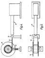
- the shell could be prepared from a tubular blank cut from an extruded plastics pipe, but an alternative method of making a tubular blank is shown in Figures 4 and 5.
- a conventional plastics extruder 12 and an extrusion die 13 are used to produce a flat ribbon extrudate 15 of essentially rectangular section. The extrudate is led to a winding drum 14 and is wound onto the drum until the desired thickness has been built up.
- a pressure roller 15 is used to press the extrudate onto the underlying layers already on the drum to ensure close intimate contact.
- the cylindrical shell blank thus produced may be subject to annealing and is then machined ready for producing an electro-fusion fitting.
- the blank is machined over its inner and outer surfaces, including the machining of the grooves 6, and is drilled with the radial holes to accept the contact terminal assemblies.
- the shell can be made to large tolerances and the machining needs only to give the approximate dimensions. It is actually best for the inside surface to be machined to a relatively rough finish, e.g. to provide a helical ridge which increases the surface area, to improve the adhesion of the injection moulded layer to this surface.
- the shell 1 constitutes an outer mould part delimiting the mould cavity with a mould core.
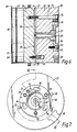
- the core is shown in Figs. 6 to 8, but it should be noted that Figure 6 is not a true section some parts, mainly bolt 24 and dowels 35, being shown out of true position for ease of illustration.
- the core has an outer cylindrical surface with circumferential end rims 20 for producing the chamfer faces 4 as described above. Spaced a short distance in from the rims are further circumferential projections 21 which define axially inwardly directed radial stop shoulders which serve to locate the outer ends of the respective heating coil sections and to hold them in position during injection of the moulding material.
- the core is made in two axial halves 22, 23 which are held together by a detachable bolt 24.
- the core half 23 is equipped with two diametrically opposed location dowels 25 which enter corresponding bores 26 in the core half 22 when the two halves are brought together.
- the core half 22 is equipped with an axial sprue bush 27 defining an inlet channel 28 for the moulding material, the inner end of the channel opening into six radial runners 30 uniformly distributed around the axis and having gates 31 opening at the cylindrical surface of the core. The runners are confined between the confronting faces of the core halves and have their gates shaped for producing the stops 5 mentioned above.
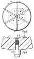
- extraction plates 32 Accommodated in recesses in the outer end faces of the core halves are extraction plates 32 fixed in position by bolts 33.
- each plate 32 there are three key-hole shaped slots 34 which are undercut behind their narrow portions enabling enlarged heads of an extraction tool to be inserted and by a small angular rotation be securely locked to the extraction plate and hence the core half.
- the bolt 24 With extraction tools so engaged with the two core havles they can be pulled apart and in opposite directions out from a completed electrofusion fitting, the bolt 24 having been removed first of course.
- the head of bolt 24 is located in a slot 35 in the extraction plate of core half 22.
- the corresponding extraction tool has a projection arranged to enter this slot and if the bolt 24 has not been removed the extraction tool cannot be engaged with the extraction plate.
- the extraction plates are provided with tapered location recesses 36. It will be noted that the sprue bush is fixed in the core half 22 by its extraction plate 32.
- the core halves are formed with removable core segments 38. When the core is inserted into the shell these segments, or at least the spaces they normally occupy, are positioned opposite the holes provided in the shell to receive the contact terminal assemblies, for reasons which are explained below.
- the coated electrical resistance wire is wound onto the core to form the two coil sections, respectively abutting with their outer ends the stop faces of rims 21, with the wire ends being left protruding at the position of the removable core segments 38.
- the core and winding are inserted axially into the previously prepared shell.
- the segments 38 are removed so that the eye connectors 8 can be crimped onto the wire ends, and the inner contact parts 9 are inserted through the eyes and into the holes in the shell.
- a mould tool bung 39 (Fig. 9) generally formed as a bolt is screwed into each contact part 9 and serves to clamp it firmly against the interior surface of the shell.
- the segments are then replaced and the entire assembly of shell and core is loaded into a suitable injection moulding machine.
- the thermoplastics material is injected through the sprue bush and enters the cavity confined between the shell 1 and core via the runners 30 and gates 31 to fill this space and thereby form the layer 3 for holding the winding on the interior surface of the shell.
- the assembly is removed from the moulding machine and the core halves 22, 23 can be removed by extraction tools engaged with the core halves as explained above. All that remains to complete the fitting is to remove the mould tool bungs 39 and insert in their place the outer contact parts 10.
- the outer contact parts may be fitted only when the electro-fusion is ready to be used to produce a welded pipe joint. It will be noted that apart from being convenient from a manufacturing viewpoint the two-part contact assembly has the advantage that different outer contact parts could be applied, e.g. to suit the particular contact configurations of different control devices which may be used to supply electric power to the fitting.
Applications Claiming Priority (2)
| Application Number | Priority Date | Filing Date | Title |
|---|---|---|---|
| GB8910070 | 1989-05-03 | ||
| GB898910070A GB8910070D0 (en) | 1989-05-03 | 1989-05-03 | Electro-fusion fittings |
Publications (3)
| Publication Number | Publication Date |
|---|---|
| EP0396273A2 true EP0396273A2 (fr) | 1990-11-07 |
| EP0396273A3 EP0396273A3 (fr) | 1993-09-08 |
| EP0396273B1 EP0396273B1 (fr) | 1995-12-27 |
Family
ID=10656093
Family Applications (1)
| Application Number | Title | Priority Date | Filing Date |
|---|---|---|---|
| EP90304013A Expired - Lifetime EP0396273B1 (fr) | 1989-05-03 | 1990-04-12 | Manchons électrosoudables |
Country Status (9)
| Country | Link |
|---|---|
| US (1) | US5163713A (fr) |
| EP (1) | EP0396273B1 (fr) |
| JP (1) | JPH02304291A (fr) |
| AT (1) | ATE132076T1 (fr) |
| DE (1) | DE69024402T2 (fr) |
| ES (1) | ES2083999T3 (fr) |
| GB (1) | GB8910070D0 (fr) |
| TR (1) | TR26263A (fr) |
| YU (1) | YU47792B (fr) |
Cited By (9)
| Publication number | Priority date | Publication date | Assignee | Title |
|---|---|---|---|---|
| EP0535247A1 (fr) * | 1991-04-19 | 1993-04-07 | Sekisui Kagaku Kogyo Kabushiki Kaisha | Raccord pour conduites |
| EP0635354A1 (fr) * | 1993-07-23 | 1995-01-25 | Streng Plastic AG | Manchon électro-soudable |
| WO1995008854A1 (fr) * | 1993-09-22 | 1995-03-30 | Georg Fischer Rohrleitungssysteme Ag | Procede de fabrication d'une piece moulee et piece moulee en matiere plastique |
| EP0652687A2 (fr) * | 1993-11-09 | 1995-05-10 | Mitsubishi Plastics Inc. | Procédé et appareil pour l'enroulement d'un fil chauffant |
| WO1995026873A1 (fr) * | 1994-03-31 | 1995-10-12 | Glynwed Plastics Ltd. | Perfectionnements se rapportant a des dispositifs de couplage par electrofusion |
| EP0679500A3 (fr) * | 1994-04-28 | 1996-10-23 | Glynwed Plastics | Procédé pour la fabrication d'un manchon d'électrosoudage. |
| WO1999012720A1 (fr) * | 1997-09-05 | 1999-03-18 | Tooler Oy | Procede et dispositif de support des extremites d'un fil de resistance dans un moule a injection lors de la fabrication de raccords tubulaires en plastique thermosoudes electriquement |
| CN103072240A (zh) * | 2013-01-29 | 2013-05-01 | 江苏双腾管业有限公司 | 抽芯绕线机 |
| EP2815164A4 (fr) * | 2012-02-17 | 2015-11-04 | Core Linepipe Inc | Tuyau, raccord de tuyau et système de canalisation |
Families Citing this family (15)
| Publication number | Priority date | Publication date | Assignee | Title |
|---|---|---|---|---|
| US5150922A (en) * | 1989-01-11 | 1992-09-29 | Osaka Gas Co., Ltd. | Electrofusion joint and hot water supply header using the same |
| GB9105937D0 (en) * | 1991-03-20 | 1991-05-08 | Victaulic Plc | Weldable pipe fittings and pipe joints formed therewith |
| FR2692020B1 (fr) * | 1992-06-04 | 1996-01-26 | Innoge Sam | Raccord thermosoudable pour tubes en un materiau plastique et son procede de fabrication. |
| US5618065A (en) * | 1994-07-21 | 1997-04-08 | Hitachi Metals, Ltd. | Electric welding pipe joint having a two layer outer member |
| US5916468A (en) * | 1996-07-08 | 1999-06-29 | Hitachi Metals Ltd. | Electrically weldable pipe joint and production method thereof |
| US6406587B1 (en) * | 1999-09-30 | 2002-06-18 | Connectra Fusion Technologies, Llc | Method and an apparatus for fusing a sidewall fitting onto a plastic pipe |
| US20060202471A1 (en) * | 2005-03-07 | 2006-09-14 | Weisbond Bradley K | Electro-fusion joining system for thermoplastic piping systems |
| ITMI20062503A1 (it) * | 2006-12-22 | 2008-06-23 | Geco System Spa | Metodo e assieme per riparare giuntare o irrobustire tubi in materiale plastico |
| US9296154B1 (en) * | 2008-08-07 | 2016-03-29 | Mcelroy Manufacturing, Inc. | Tapered wattage radial heater |
| DK2780159T3 (en) | 2011-11-16 | 2019-04-08 | Shawcor Ltd | Flexible reinforced pipeline and reinforcement tape |
| DK2780619T3 (en) * | 2011-11-16 | 2018-11-19 | Shawcor Ltd | PIPE CONNECTION DEVICE AND PROCEDURE |
| CN103968177B (zh) * | 2014-04-30 | 2016-03-02 | 永高股份有限公司 | 带有外显示标记和电阻丝限位装置的聚乙烯电熔承口管件 |
| CN105972344B (zh) * | 2016-05-25 | 2018-05-01 | 北京航空航天大学 | 一种大口径增强管材的连接结构 |
| CN107053595A (zh) * | 2016-11-07 | 2017-08-18 | 广东永高塑业发展有限公司 | 一种电熔承插式缠绕管承口模具及其使用方法 |
| EP3434454B1 (fr) * | 2017-07-26 | 2023-03-01 | Georg Fischer Wavin AG | Union élastique par soudure électrique |
Citations (12)
| Publication number | Priority date | Publication date | Assignee | Title |
|---|---|---|---|---|
| DE1048106B (de) * | 1956-05-03 | 1958-12-31 | Sued West Chemie Gmbh | Durch Schweissen zu verbindende Formstuecke, insbesondere Fittings, aus thermoplastischen Kunststoffen |
| GB828442A (en) * | 1956-04-09 | 1960-02-17 | Painton & Co Ltd | Improvements in or relating to electrical components such as variable electric resistances, potentiometers, and the like |
| US2955322A (en) * | 1958-07-02 | 1960-10-11 | Kaul Clay Company | Apparatus for forming a liner having a resilient ring-shaped gasket anchored therein in the socket of a pipe member |
| DE1111814B (de) * | 1956-08-31 | 1961-07-27 | Sued West Chemie Gmbh | Verfahren zur Herstellung eines als Verbindungsmuffe von Kunststoffrohren geeignetenSchweissfittings |
| DE1939955A1 (de) * | 1968-08-08 | 1970-02-12 | Plastifiber S R L | Verfahren zum Herstellen von Rohren oder aehnlichen Gegenstaenden und Rohr od.dgl. |
| DE2053938A1 (de) * | 1970-10-26 | 1972-04-27 | Mannesmann Ag | Verfahren und Vorrichtung zum Herstel len einer zum Verbinden von thermoplasti sehen Kunststoffrohren dienenden Schweiß muffe |
| GB2036518A (en) * | 1978-05-02 | 1980-06-25 | Stum W | Thermoplastic welding sleeve |
| EP0036963A1 (fr) * | 1980-03-31 | 1981-10-07 | Georg Fischer Aktiengesellschaft | Manchon de soudage pour matières thermoplastiques, procédé et appareil pour sa fabrication |
| EP0221396A1 (fr) * | 1985-10-24 | 1987-05-13 | Glynwed Tubes & Fittings Limited | Manchon électro-fusible |
| WO1987005373A1 (fr) * | 1986-02-28 | 1987-09-11 | Frese A/S | Procede de moulage d'un robinet a boisseau spherique par montage d'elements maintenus a l'aide d'outils constituant des noyaux |
| US4714576A (en) * | 1985-12-16 | 1987-12-22 | General Motors Corporation | Method of manufacturing a polyphenylene sulfide potted pole and coil assembly |
| EP0260014A2 (fr) * | 1986-09-09 | 1988-03-16 | Uponor Bv | Procédé de fabrication de manchons thermoplastiques soudables |
Family Cites Families (14)
| Publication number | Priority date | Publication date | Assignee | Title |
|---|---|---|---|---|
| US3394952A (en) * | 1965-05-03 | 1968-07-30 | Ben B. Garrett | Sewer pipe joint |
| GB1222041A (en) * | 1968-03-19 | 1971-02-10 | Johns Manville | Improvements relating to pipe fittings |
| US3784239A (en) * | 1971-09-07 | 1974-01-08 | J Carter | Sealed, filament-wound plastic sleeve |
| FR2353381A1 (fr) * | 1976-06-03 | 1977-12-30 | Pont A Mousson | Procede d'assemblage par soudure de tubes plastiques et raccord pour un tel assemblage |
| DE3268829D1 (en) * | 1981-09-30 | 1986-03-13 | Fusion Plastics Ltd | Electro-fusion fitting |
| CH652473A5 (de) * | 1981-10-02 | 1985-11-15 | Fischer Ag Georg | Schweissverbindung fuer kunststoffrohre. |
| US4436988A (en) * | 1982-03-01 | 1984-03-13 | R & G Sloane Mfg. Co., Inc. | Spiral bifilar welding sleeve |
| NL8303190A (nl) * | 1983-09-15 | 1985-04-01 | Wavin Bv | Buisverbinding van vezelversterkte kunststofbuisdelen. |
| CH661475A5 (de) * | 1983-12-19 | 1987-07-31 | Fischer Ag Georg | Anordnung zum verschweissen von formteilen aus thermoplastischem kunststoff. |
| US4605156A (en) * | 1985-02-25 | 1986-08-12 | General Dynamics Corporation/Convair Div. | Cold welded joint |
| US4602148A (en) * | 1985-05-16 | 1986-07-22 | Central Plastics Company | Thermoplastic fitting electric heat welding method and apparatus |
| CH671444A5 (fr) * | 1986-06-25 | 1989-08-31 | Fischer Ag Georg | |
| NL8700299A (nl) * | 1987-02-09 | 1988-09-01 | Wavin Bv | Lasmof uit thermoplastische kunststof, werkwijze voor het vormen van een dergelijke lasmof alsmede gereedschap voor gebruik bij het uitvoeren van een dergelijke werkwijze. |
| US4852914A (en) * | 1987-06-19 | 1989-08-01 | Milfuse Systems, Inc. | Plastic pipeline having rapidly fusible joints and method of making same |
-
1989
- 1989-05-03 GB GB898910070A patent/GB8910070D0/en active Pending
-
1990
- 1990-01-08 YU YU3090A patent/YU47792B/sh unknown
- 1990-04-12 EP EP90304013A patent/EP0396273B1/fr not_active Expired - Lifetime
- 1990-04-12 AT AT90304013T patent/ATE132076T1/de active
- 1990-04-12 ES ES90304013T patent/ES2083999T3/es not_active Expired - Lifetime
- 1990-04-12 DE DE69024402T patent/DE69024402T2/de not_active Expired - Fee Related
- 1990-04-19 TR TR90/0416A patent/TR26263A/xx unknown
- 1990-05-02 US US07/517,725 patent/US5163713A/en not_active Expired - Fee Related
- 1990-05-02 JP JP2116714A patent/JPH02304291A/ja active Pending
Patent Citations (12)
| Publication number | Priority date | Publication date | Assignee | Title |
|---|---|---|---|---|
| GB828442A (en) * | 1956-04-09 | 1960-02-17 | Painton & Co Ltd | Improvements in or relating to electrical components such as variable electric resistances, potentiometers, and the like |
| DE1048106B (de) * | 1956-05-03 | 1958-12-31 | Sued West Chemie Gmbh | Durch Schweissen zu verbindende Formstuecke, insbesondere Fittings, aus thermoplastischen Kunststoffen |
| DE1111814B (de) * | 1956-08-31 | 1961-07-27 | Sued West Chemie Gmbh | Verfahren zur Herstellung eines als Verbindungsmuffe von Kunststoffrohren geeignetenSchweissfittings |
| US2955322A (en) * | 1958-07-02 | 1960-10-11 | Kaul Clay Company | Apparatus for forming a liner having a resilient ring-shaped gasket anchored therein in the socket of a pipe member |
| DE1939955A1 (de) * | 1968-08-08 | 1970-02-12 | Plastifiber S R L | Verfahren zum Herstellen von Rohren oder aehnlichen Gegenstaenden und Rohr od.dgl. |
| DE2053938A1 (de) * | 1970-10-26 | 1972-04-27 | Mannesmann Ag | Verfahren und Vorrichtung zum Herstel len einer zum Verbinden von thermoplasti sehen Kunststoffrohren dienenden Schweiß muffe |
| GB2036518A (en) * | 1978-05-02 | 1980-06-25 | Stum W | Thermoplastic welding sleeve |
| EP0036963A1 (fr) * | 1980-03-31 | 1981-10-07 | Georg Fischer Aktiengesellschaft | Manchon de soudage pour matières thermoplastiques, procédé et appareil pour sa fabrication |
| EP0221396A1 (fr) * | 1985-10-24 | 1987-05-13 | Glynwed Tubes & Fittings Limited | Manchon électro-fusible |
| US4714576A (en) * | 1985-12-16 | 1987-12-22 | General Motors Corporation | Method of manufacturing a polyphenylene sulfide potted pole and coil assembly |
| WO1987005373A1 (fr) * | 1986-02-28 | 1987-09-11 | Frese A/S | Procede de moulage d'un robinet a boisseau spherique par montage d'elements maintenus a l'aide d'outils constituant des noyaux |
| EP0260014A2 (fr) * | 1986-09-09 | 1988-03-16 | Uponor Bv | Procédé de fabrication de manchons thermoplastiques soudables |
Cited By (21)
| Publication number | Priority date | Publication date | Assignee | Title |
|---|---|---|---|---|
| EP0535247A4 (en) * | 1991-04-19 | 1993-09-08 | Sekisui Kagaku Kogyo Kabushiki Kaisha | Pipe joint member |
| US5398974A (en) * | 1991-04-19 | 1995-03-21 | Sekisui Kagaku Kogyo Kabushiki Kaisha | Pipe connecting member |
| EP0535247A1 (fr) * | 1991-04-19 | 1993-04-07 | Sekisui Kagaku Kogyo Kabushiki Kaisha | Raccord pour conduites |
| EP0635354A1 (fr) * | 1993-07-23 | 1995-01-25 | Streng Plastic AG | Manchon électro-soudable |
| US5674588A (en) * | 1993-09-22 | 1997-10-07 | Georg Fischer Rohrleitungssysteme Ag | Welding sleeve for plastic pipe |
| WO1995008854A1 (fr) * | 1993-09-22 | 1995-03-30 | Georg Fischer Rohrleitungssysteme Ag | Procede de fabrication d'une piece moulee et piece moulee en matiere plastique |
| EP0652687A2 (fr) * | 1993-11-09 | 1995-05-10 | Mitsubishi Plastics Inc. | Procédé et appareil pour l'enroulement d'un fil chauffant |
| EP0652687A3 (fr) * | 1993-11-09 | 1995-12-20 | - | Procédé et appareil pour l'enroulement d'un fil chauffant. |
| KR100327284B1 (ko) * | 1993-11-09 | 2002-06-24 | 미야베 요시까즈 | 전열선의권선방법및그장치 |
| US5581872A (en) * | 1993-11-09 | 1996-12-10 | Mitsubishi Plastics, Inc. | Method for winding a heating wire |
| US5862585A (en) * | 1994-03-31 | 1999-01-26 | Glynwed Pipe Systems Limited | Electrofusion couplers and method and apparatus for manufacturing |
| WO1995026873A1 (fr) * | 1994-03-31 | 1995-10-12 | Glynwed Plastics Ltd. | Perfectionnements se rapportant a des dispositifs de couplage par electrofusion |
| US5697143A (en) * | 1994-04-28 | 1997-12-16 | Glynwed Plastics Ltd. | Method of manufacturing an electrofusion coupler |
| AU689213B2 (en) * | 1994-04-28 | 1998-03-26 | Glynwed Pipe Systems Limited | Method of manufacturing an electrofusion coupler |
| EP0679500A3 (fr) * | 1994-04-28 | 1996-10-23 | Glynwed Plastics | Procédé pour la fabrication d'un manchon d'électrosoudage. |
| WO1999012720A1 (fr) * | 1997-09-05 | 1999-03-18 | Tooler Oy | Procede et dispositif de support des extremites d'un fil de resistance dans un moule a injection lors de la fabrication de raccords tubulaires en plastique thermosoudes electriquement |
| EP2815164A4 (fr) * | 2012-02-17 | 2015-11-04 | Core Linepipe Inc | Tuyau, raccord de tuyau et système de canalisation |
| US9857003B2 (en) | 2012-02-17 | 2018-01-02 | Core Linepipe Inc. | Pipe, pipe connection and pipeline system |
| US10544889B2 (en) | 2012-02-17 | 2020-01-28 | Core Linepipe Inc. | Pipe, pipe connection and pipeline system |
| CN103072240A (zh) * | 2013-01-29 | 2013-05-01 | 江苏双腾管业有限公司 | 抽芯绕线机 |
| CN103072240B (zh) * | 2013-01-29 | 2014-11-26 | 江苏双腾管业有限公司 | 抽芯绕线机 |
Also Published As
| Publication number | Publication date |
|---|---|
| EP0396273A3 (fr) | 1993-09-08 |
| US5163713A (en) | 1992-11-17 |
| JPH02304291A (ja) | 1990-12-18 |
| DE69024402T2 (de) | 1996-05-15 |
| EP0396273B1 (fr) | 1995-12-27 |
| YU3090A (sh) | 1994-06-10 |
| DE69024402D1 (de) | 1996-02-08 |
| TR26263A (tr) | 1995-02-15 |
| ES2083999T3 (es) | 1996-05-01 |
| YU47792B (sr) | 1996-01-09 |
| ATE132076T1 (de) | 1996-01-15 |
| GB8910070D0 (en) | 1989-06-21 |
Similar Documents
| Publication | Publication Date | Title |
|---|---|---|
| EP0396273B1 (fr) | Manchons électrosoudables | |
| US5228186A (en) | Method of manufacturing electro-fusion fittings | |
| EP0693652B1 (fr) | Raccord de tuyaux electrosoudable | |
| CA1193631A (fr) | Raccord de tuyauterie en matiere plastique | |
| EP0535247B1 (fr) | Raccord pour conduites | |
| EP0055891B1 (fr) | Méthode de fabrication de joints soudés à l'autogène pour accessoires de raccordement | |
| EP2215394B1 (fr) | Ensemble de collier de prise | |
| CA1270612A (fr) | Methode de fabrication de raccords thermoplastiques thermosoudables | |
| US5697143A (en) | Method of manufacturing an electrofusion coupler | |
| JP2530785B2 (ja) | 電気融着継手の製造方法 | |
| GB2312264A (en) | Pipe fitting construction and method | |
| JPH0716945A (ja) | 中空体製品の成形方法および成形用金型 | |
| JP2849349B2 (ja) | 電気融着継手とその製造方法及びその射出成形用金型 | |
| JP2939032B2 (ja) | 電気融着式プラスチック管継手の製造方法 | |
| JPH1137374A (ja) | 電気融着式配管部材及び電気融着式配管部材の製造方法 | |
| KR20010023300A (ko) | 전기적으로 가열 용접가능한 플라스틱 튜브 피팅을제조하는 동안 인젝션 모울드 내에서 저항 와이어의단부를 지지하기 위한 방법 및 장치 | |
| JP3043123B2 (ja) | 電気融着継手の製造方法 | |
| JPH079559A (ja) | 電気融着式プラスチック管継手の製造方法 | |
| HRP920372A2 (en) | Electro-fusion fittings | |
| JPH0880543A (ja) | 電気融着継手の製造方法 | |
| JP3143838B2 (ja) | 電気融着継手の製造方法 | |
| JPH05157189A (ja) | 電気融着式プラスチック管継手 | |
| JPH09170685A (ja) | 管継手および管継手の成形方法 | |
| JPH07132555A (ja) | フランジ付樹脂ライニング鋼管の製造方法 | |
| JPH09229282A (ja) | 電気融着継手の製造方法 |
Legal Events
| Date | Code | Title | Description |
|---|---|---|---|
| PUAI | Public reference made under article 153(3) epc to a published international application that has entered the european phase |
Free format text: ORIGINAL CODE: 0009012 |
|
| AK | Designated contracting states |
Kind code of ref document: A2 Designated state(s): AT BE CH DE DK ES FR GB GR IT LI LU NL SE |
|
| RAP1 | Party data changed (applicant data changed or rights of an application transferred) |
Owner name: FUSION GROUP PLC |
|
| PUAL | Search report despatched |
Free format text: ORIGINAL CODE: 0009013 |
|
| AK | Designated contracting states |
Kind code of ref document: A3 Designated state(s): AT BE CH DE DK ES FR GB GR IT LI LU NL SE |
|
| 17P | Request for examination filed |
Effective date: 19940303 |
|
| 17Q | First examination report despatched |
Effective date: 19950404 |
|
| GRAA | (expected) grant |
Free format text: ORIGINAL CODE: 0009210 |
|
| AK | Designated contracting states |
Kind code of ref document: B1 Designated state(s): AT BE CH DE DK ES FR GB GR IT LI LU NL SE |
|
| PG25 | Lapsed in a contracting state [announced via postgrant information from national office to epo] |
Ref country code: NL Free format text: LAPSE BECAUSE OF FAILURE TO SUBMIT A TRANSLATION OF THE DESCRIPTION OR TO PAY THE FEE WITHIN THE PRESCRIBED TIME-LIMIT Effective date: 19951227 Ref country code: LI Effective date: 19951227 Ref country code: GR Free format text: LAPSE BECAUSE OF FAILURE TO SUBMIT A TRANSLATION OF THE DESCRIPTION OR TO PAY THE FEE WITHIN THE PRESCRIBED TIME-LIMIT Effective date: 19951227 Ref country code: DK Effective date: 19951227 Ref country code: CH Effective date: 19951227 Ref country code: BE Effective date: 19951227 Ref country code: AT Effective date: 19951227 |
|
| REF | Corresponds to: |
Ref document number: 132076 Country of ref document: AT Date of ref document: 19960115 Kind code of ref document: T |
|
| ITF | It: translation for a ep patent filed |
Owner name: JACOBACCI & PERANI S.P.A. |
|
| REF | Corresponds to: |
Ref document number: 69024402 Country of ref document: DE Date of ref document: 19960208 |
|
| PG25 | Lapsed in a contracting state [announced via postgrant information from national office to epo] |
Ref country code: SE Effective date: 19960327 |
|
| ET | Fr: translation filed | ||
| PG25 | Lapsed in a contracting state [announced via postgrant information from national office to epo] |
Ref country code: LU Free format text: LAPSE BECAUSE OF NON-PAYMENT OF DUE FEES Effective date: 19960430 |
|
| REG | Reference to a national code |
Ref country code: ES Ref legal event code: FG2A Ref document number: 2083999 Country of ref document: ES Kind code of ref document: T3 |
|
| NLV1 | Nl: lapsed or annulled due to failure to fulfill the requirements of art. 29p and 29m of the patents act | ||
| PLBE | No opposition filed within time limit |
Free format text: ORIGINAL CODE: 0009261 |
|
| STAA | Information on the status of an ep patent application or granted ep patent |
Free format text: STATUS: NO OPPOSITION FILED WITHIN TIME LIMIT |
|
| 26N | No opposition filed | ||
| PGFP | Annual fee paid to national office [announced via postgrant information from national office to epo] |
Ref country code: GB Payment date: 19980403 Year of fee payment: 9 |
|
| PGFP | Annual fee paid to national office [announced via postgrant information from national office to epo] |
Ref country code: FR Payment date: 19980409 Year of fee payment: 9 |
|
| PGFP | Annual fee paid to national office [announced via postgrant information from national office to epo] |
Ref country code: DE Payment date: 19980417 Year of fee payment: 9 |
|
| PGFP | Annual fee paid to national office [announced via postgrant information from national office to epo] |
Ref country code: ES Payment date: 19980428 Year of fee payment: 9 |
|
| PG25 | Lapsed in a contracting state [announced via postgrant information from national office to epo] |
Ref country code: GB Free format text: LAPSE BECAUSE OF NON-PAYMENT OF DUE FEES Effective date: 19990412 |
|
| PG25 | Lapsed in a contracting state [announced via postgrant information from national office to epo] |
Ref country code: ES Free format text: LAPSE BECAUSE OF NON-PAYMENT OF DUE FEES Effective date: 19990413 |
|
| GBPC | Gb: european patent ceased through non-payment of renewal fee |
Effective date: 19990412 |
|
| PG25 | Lapsed in a contracting state [announced via postgrant information from national office to epo] |
Ref country code: FR Free format text: LAPSE BECAUSE OF NON-PAYMENT OF DUE FEES Effective date: 19991231 |
|
| REG | Reference to a national code |
Ref country code: FR Ref legal event code: ST |
|
| PG25 | Lapsed in a contracting state [announced via postgrant information from national office to epo] |
Ref country code: DE Free format text: LAPSE BECAUSE OF NON-PAYMENT OF DUE FEES Effective date: 20000201 |
|
| REG | Reference to a national code |
Ref country code: ES Ref legal event code: FD2A Effective date: 20010503 |
|
| PG25 | Lapsed in a contracting state [announced via postgrant information from national office to epo] |
Ref country code: IT Free format text: LAPSE BECAUSE OF NON-PAYMENT OF DUE FEES;WARNING: LAPSES OF ITALIAN PATENTS WITH EFFECTIVE DATE BEFORE 2007 MAY HAVE OCCURRED AT ANY TIME BEFORE 2007. THE CORRECT EFFECTIVE DATE MAY BE DIFFERENT FROM THE ONE RECORDED. Effective date: 20050412 |