EP0393935A2 - Système pour la détermination de la position d'un véhicule - Google Patents
Système pour la détermination de la position d'un véhicule Download PDFInfo
- Publication number
- EP0393935A2 EP0393935A2 EP90303988A EP90303988A EP0393935A2 EP 0393935 A2 EP0393935 A2 EP 0393935A2 EP 90303988 A EP90303988 A EP 90303988A EP 90303988 A EP90303988 A EP 90303988A EP 0393935 A2 EP0393935 A2 EP 0393935A2
- Authority
- EP
- European Patent Office
- Prior art keywords
- location
- vehicle
- optimum
- estimated location
- estimated
- Prior art date
- Legal status (The legal status is an assumption and is not a legal conclusion. Google has not performed a legal analysis and makes no representation as to the accuracy of the status listed.)
- Granted
Links
Images

Classifications
-
- G—PHYSICS
- G01—MEASURING; TESTING
- G01S—RADIO DIRECTION-FINDING; RADIO NAVIGATION; DETERMINING DISTANCE OR VELOCITY BY USE OF RADIO WAVES; LOCATING OR PRESENCE-DETECTING BY USE OF THE REFLECTION OR RERADIATION OF RADIO WAVES; ANALOGOUS ARRANGEMENTS USING OTHER WAVES
- G01S19/00—Satellite radio beacon positioning systems; Determining position, velocity or attitude using signals transmitted by such systems
- G01S19/38—Determining a navigation solution using signals transmitted by a satellite radio beacon positioning system
- G01S19/39—Determining a navigation solution using signals transmitted by a satellite radio beacon positioning system the satellite radio beacon positioning system transmitting time-stamped messages, e.g. GPS [Global Positioning System], GLONASS [Global Orbiting Navigation Satellite System] or GALILEO
- G01S19/42—Determining position
- G01S19/48—Determining position by combining or switching between position solutions derived from the satellite radio beacon positioning system and position solutions derived from a further system
- G01S19/49—Determining position by combining or switching between position solutions derived from the satellite radio beacon positioning system and position solutions derived from a further system whereby the further system is an inertial position system, e.g. loosely-coupled
-
- G—PHYSICS
- G01—MEASURING; TESTING
- G01C—MEASURING DISTANCES, LEVELS OR BEARINGS; SURVEYING; NAVIGATION; GYROSCOPIC INSTRUMENTS; PHOTOGRAMMETRY OR VIDEOGRAMMETRY
- G01C21/00—Navigation; Navigational instruments not provided for in groups G01C1/00 - G01C19/00
- G01C21/26—Navigation; Navigational instruments not provided for in groups G01C1/00 - G01C19/00 specially adapted for navigation in a road network
- G01C21/28—Navigation; Navigational instruments not provided for in groups G01C1/00 - G01C19/00 specially adapted for navigation in a road network with correlation of data from several navigational instruments
- G01C21/30—Map- or contour-matching
Definitions
- the present invention relates in general to a vehicle location detecting system, and in particular to a vehicle location detecting system wherein the location of a vehicle is estimated with the aid of distance and heading sensors, and wherein pattern matching between the estimated location and the road network data obtained from a road map memory is performed, and wherein thc vehicle location is detected in accordance with a degree of similarity (S) of the vehicle on each road (rate of coincidence between the path pattern taken by the vehicle and the map pattern) and in accordance with a probability area ( ⁇ ) having a certain probability of including the actual location of the vehicle.
- S degree of similarity
- ⁇ probability area
- a variety of automatic vehicle navigational systems has been developed and used to provide information about the actual location of a vehicle as it moves over streets.
- dead reckoning in which the vehicle is tracked by advancing a “dead reckoned position” from measured distances and courses or headings.
- a system based upon dead reckoning principles may, for example, detect the distance traveled and heading of the vehicle using distance and heading sensors on the vehicle.
- a vehicle location detecting system comprising: a heading sensor (3) for detecting changes in the heading of a vehicle as it moves over streets; a distance sensor (4) for detecting distances traveled by the vehicle; a road map memory (5) for storing a map data base; location detecting unit (7) for detecting a first estimated location (P G ) of the vehicle; and correction arithmetic unit (8) for calculating a second estimated location of the vehicle from the distances detected by the distance sensor (4) and the changes in the heading detected by the heading sensor (3), for detecting an optimum vehicle location (P M ) of the vehicle by calculating a degree of similarity (S) between the second estimated location and the map data base obtained from road map memory (5), for calculating a first probability area ( ⁇ G ) of the first estimated location (P G ) including an actual location of the vehicle and a second probability area ( ⁇ M ) of the optimum vehicle location (P M ) including an actual location of the vehicle, and for
- the estimated location obtained from the satellites is automatically employed. That is, the optimum estimated location obtained by the current estimating means is replaced with the estimated location obtained by the GSP receiver.
- the optimum vehicle location by the road matching process is automatically employed. That is, the optimum vehicle location obtained by the road matching is outputted as a current location of the vehicle without being corrected.
- the accuracy of the vehicle location calculated by the road matching process is not favorable, then either the estimated location P G or optimum vehicle location is employed taking account of the accuracy of the road matching and the received state from the satellites.
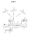
- the vehicle location detecting system comprises a console 1, a display 2, a heading sensor 3, a distance sensor 4, a road map memory 5 for storing a map data base, road network data base and similar data base, a memory drive 6 for reading data from the road map memory 5, a GPS (Global Positioning System) receiver 7 for receiving radio waves from satellites 7a, 7b and 7c in order to detect the location of the receiver 7 itself (that is, vehicle location), and a voice outputting unit 10.
- GPS Global Positioning System
- the vehicle location detecting system further comprises a processing unit 8 provided with correction arithmetic means for evaluating a degree of similarity S and a probability area ⁇ of including the actual location of a vehicle.
- the degree of similarity S and probability area ⁇ will hereinafter be described in detail.
- the processing unit 8 corrects the vehicle location with the aid of an estimated location P G of the vehicle detected by the GPS receiver 7.
- the vehicle location detecting system further comprises a navigation controller 9 for executing computation of recommended routes, retrieving and reading of a road map in a predetermined range, generation of display data to guide a vehicle operator, driving of the display 2 and voice outputting unit 10, and various arithmetic controls such as controls of the processing unit 8.
- the above described console 1 has a keyboard (not shown) which allows a vehicle operator to start and stop this vehicle location detecting system, and to move a cursor on the picture screen of the display 2 and to scroll the road map displayed on the picture screen.
- the road map memory 5 comprises a mass storage medium memory such as a CD-ROM, magnetic tape and like.
- the road map is divided into mesh blocks, and there are stored a map data base used for graphically displaying roads and coordinate location at the unit of each mesh block, and a road network data base used for route computation and road matching.
- the road network data base comprises data of roads (segments) that are interconnected by junctions (nodes) having inlet/outlet ports, distance data of segments, required time data to travel segments, road class data (freeways, major arteries, minor arteries, streets, etc.), road width data, and point data to specify specific points such as famous facilities, rivers, railways, street names and the like.
- the map data base comprises a plurality of road maps which are different in contraction scale.
- the display 2 has a transparent touch panel attached on the picture screen such a CRT (cathode Ray Tube) and a crystalline panel, and displays an initial setting menu supplied from the navigation controller 9.
- the vehicle operator touches the displayed positions of the picture screen of the display 2 to enter the set reference of a recommended route (for example, a minimum time route, shortest distance route, route having a small number of left turns and right turns, and wide route), magnification of map, destination and so on. That is, the navigation controller 9 interacts through the display 2 with the vehicle operator.
- the destination can also be entered with the keyboard of the console 1 or by selecting it from the point data containing place names, famous facilities, and points that has been stored by a vehicle operator. In addition, points on the way to the destination can be entered by the vehicle operator.
- the heading sensor 3 detects changes in the heading of the vehicle as it moves over streets, and comprises a magnetic sensor, gyro or turning-angle sensor which detects a turning angle from a difference of rotation between the left and right wheels of the vehicle.
- the distance sensor 4 is used for detecting distances traveled by a vehicle.
- the distance sensor 4 can constitute a vehicle speed sensor which senses the speed of a vehicle, or one or more wheel sensors which sense the rotation of the wheels of a vehicle.
- the navigation controller 9 obtains information about vehicle locations from the processing unit 8, and displays on the map the current location and destination of the vehicle.
- the navigation controller 9 is constituted by a microcomputer (not shown), a graphic data processor (not shown) and a picture image processing memory (not shown), and executes display of menus, retrieval of maps, switching of contraction scale, zoom scroll, display of the current location and heading of a vehicle, display of an destination or guide spots, and display of the heading and distance to an destination.
- the GPS receiver 7 measures the wave arrival time from each satellite by decoding false noise codes received from satellites 7a, 7b and 7c, and calculates an estimated location P G of the receiver 7 (vehicle location).
- the processing unit 8 integrates the distances detected by the distance sensor 4 and the amount of the heading changes detected by the heading sensor 3, and detects the location of the vehicle by comparing the integrated data with the map data that have been read out by the memory drive 6.
- the vehicle location is corrected with the aid of the data about the estimated location P G that has been obtained in the GPS receiver 7, and then the corrected vehicle location is outputted as a current location and heading of the vehicle.
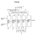
- Fig. 2 schematically illustrates the structure of the processing unit 8.
- input preprocessing means 22 receives the heading data sampled from the heading sensor 3 and distance data sampled from the distance sensor 4, and calculates an optimum estimated heading by calibration or filtering.
- current location estimating means 23 Based on the optimum estimated heading obtained from the input preprocessing means 22 and distance data, current location estimating means 23 calculates an optimum estimated location by dead reckoning. In addition, the current location estimating means 23 receives a corrected current location obtained from a location resetting means 25 to update the optimum estimated location.
- Travel road estimating means 24 calculates repeatedly the degree of similarity between the road network data base obtained from the road map memory 5 and the optimum estimated location in order to obtain an optimum vehicle location P M of the vehicle on the road, and also calculates the probability area ⁇ M of the optimum vehicle location.
- the error of location between the optimum estimated location obtained from the current location estimating means 23 by dead reckoning and the actual location of the vehicle is first calculated.
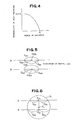
- the degree of similarity between the above described optimum estimated location and the road network data is then calculated to obtain a probability of matching with an actual road road. Consequently, the relationship between the location error and the road matching probability (degree of similarity) is obtained as shown in Fig. 4. That is, if the location error is small, then the optimum vehicle location P M can be certainly obtained on a road, while the degree of similarity between the optimum estimated location and the road pattern is being calculated repeatedly during travel. In other words, the vehicle location can be specified on a specific road.
- the location error becomes larger and larger, the matching probability is greatly reduced even if the degree of similarity to the road pattern is calculated. If the location error (meter) becomes larger than the point e (meter) shown in Fig. 4, the map matching is no longer applicable even if the degree of similarity is calculated repeatedly. In that case, it becomes necessary that the optimum estimated location obtained from the current location estimating means 23 by dead reckoning is corrected by some methods, because the vehicle location cannot be specified on a specific road.
- the administrative judgement means 21 corrects the vehicle location with the aid of the estimated location P G that has been obtained from the GPS receiver 7 under a certain condition, and feeds the corrected location back to the current location estimating means 23.
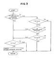
- step 1 of Fig. 3 the travel road estimating means 24 repeatedly calculates, over a certain travel distance (for example, more than 2 Km), the degree of similarity between the road network data base obtained from the road map memory 5 and the optimum estimated location that has been obtained from the current location estimating means 23 by dead reckoning, and determines if an optimum vehicle location has been obtained with the aid of the calculated degree of similarity. If no, the step 1 advances to step 2.
- a certain travel distance for example, more than 2 Km
- step 2 it is determined if the vehicle has traveled over a predetermined distance lo after the previous vehicle location was corrected. If no, the step 2 advances to a "return" in order to avoid that the correction becomes complicated. If the vehicle has traveled over the predetermined distance lo, the step 2 advances to step 3, in which the optimum estimated location that has been obtained by dead reckoning is replaced with the estimated location P G obtained from the GPS receiver 7. That is, since the vehicle location cannot be obtained by the road matching, the estimated location P G obtained from the GPS receiver 7 is automatically employed as an optimum estimated location.
- step 1 advances to step 4, in which a difference ⁇ d between the estimated location P G obtained from the GPS receiver 7 and the optimum vehicle location P M obtained in the travel road estimating means 24 by the road matching (degree of similarity) is calculated, and it is determined if the difference ⁇ d is above a first reference value d1 (for example, 50 m). If the difference ⁇ d is below the first reference value d1, then the optimum vehicle location P M obtained by the road matching is considered to be more accurate (that is, the optimum vehicle location P M is not corrected and becomes a current location of the vehicle), and the step 4 advances to the "return".
- a first reference value d1 for example, 50 m
- step 4 advances to step 5, in which the status signal obtained from the GSP receiver 7 is checked, and it is determined if the received status is favorable.
- the received status is intended to mean a ranking representing the detection accuracy of a received position (vehicle location) determined from the arrangement state of satellites or the detection accuracy of a received position (vehicle location) determined from the level or interrupted state of the received radio waves.
- the main reason that the received status is checked is that the accuracy of the estimated location P G changes depending upon the arrangement state of the satellites or that if the vehicle travels between high buildings, under elevated roads or under trees, the radio waves from the satellites are weakened and therefore the reliability of location information obtained is relatively reduced.
- the location detection accuracy is reduced to about 100 m if the received state is deteriorated. If the received status is favorable, the error in the estimated location P G of the vehicle by the satellites is considered to be smaller than the error in the optimum vehicle location P M obtained by the map matching, and the step S5 advances to the step S2.
- step S5 advances to step S6, wherein it is determined if the above described difference ⁇ d is above a second reference value d2 (for example, e meter shown in Fig. 4).
- a second reference value d2 for example, e meter shown in Fig. 4.
- the reason that the second reference value d2 is employed is based on the presupposition that even if the received status is not favorable, the estimated location P G obtained from the GPS receiver 7 will be smaller in error than the optimum estimated location having no possibility of matching with a road.
- the step S6 advances to the "return" without employing the estimated location P G obtained from the GPS receiver 7, because the received status is not favorable. If the difference ⁇ d is above the second reference value d2, the step S6 advances to the step 2 to employ the estimated location P G obtained from the GPS system even if the received status is not favorable.
- the estimated location P G obtained from the satellites 7a, 7b and 7c is automatically employed. That is, the optimum estimated location obtained by the current estimating means 23 is replaced with the estimated location PG obtained by the GSP receiver 7.
- the optimum vehicle location P M by the road matching process is automatically employed. That is, the optimum vehicle location P M obtained by the road matching is outputted as a current location of the vehicle without being corrected.
- the accuracy of the vehicle location calculated by the road matching process is not favorable, then either the estimated location P G or optimum vehicle location P M is employed taking account of the accuracy of the road matching and the received state from the satellites.
- the optimum estimated location is replaced using the estimated location P G obtained from the GPS receiver 7.
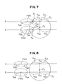
- Figs. 5-7 there is a method shown in Figs. 5-7. Assume that two roads A and B are qualified as roads that are subjected to the road matching. At this time, the degrees of similarity in the roads A and B are S MA and S MB , respectively, and the probability areas in the roads A and B are ⁇ MA and ⁇ MB , respectively.
- a vehicle location PMA or PMB located within a larger degree of similarity S MA or S MB becomes an optimum vehicle location.
- the estimated location P G obtained by the GPS receiver 7 and the probability area ⁇ G of the estimated location P G are obtained as shown in Fig. 6. If the vehicle is moving on a road, it should be located on the road A or B. Therefore, an intersection P GA between the road A and a vertical line from the estimated location P GA to the road A is obtained as a vehicle location on a road, and the probability area in the road A becomes ⁇ GA , as shown in Fig. 6. Likewise, an intersection P GB between the road B and a vertical line from the estimated location P G to the road B is obtained as a vehicle location on a road, and the probability area in the road B becomes ⁇ GB .
- the vehicle location P B can be employed as an optimum estimated location and optimum vehicle location.
- the optimum estimated location is merely replaced using the estimated location P G obtained by the GPS receiver 7.
- the vehicle location P B can be obtained by the above described equations (2) and (4).
- the GPS receiver 7 may be connected to the navigation controller 9. In that case, a position signal from the GPS receiver 7 is supplied through the navigation controller 9 to the processing unit 8.
- the estimated location of the vehicle can be obtained by a geostationary satellite system.
- the estimated location may also be obtained by signposts that typically are, for example, low power radio transmitters located on streets to sense and transmit information identifying the location of a passing vehicle.
Applications Claiming Priority (2)
| Application Number | Priority Date | Filing Date | Title |
|---|---|---|---|
| JP1096741A JPH0792388B2 (ja) | 1989-04-17 | 1989-04-17 | 位置検出装置 |
| JP96741/89 | 1989-04-17 |
Publications (3)
| Publication Number | Publication Date |
|---|---|
| EP0393935A2 true EP0393935A2 (fr) | 1990-10-24 |
| EP0393935A3 EP0393935A3 (fr) | 1992-01-15 |
| EP0393935B1 EP0393935B1 (fr) | 1995-03-08 |
Family
ID=14173122
Family Applications (1)
| Application Number | Title | Priority Date | Filing Date |
|---|---|---|---|
| EP90303988A Expired - Lifetime EP0393935B1 (fr) | 1989-04-17 | 1990-04-12 | Système pour la détermination de la position d'un véhicule |
Country Status (4)
| Country | Link |
|---|---|
| US (1) | US5119301A (fr) |
| EP (1) | EP0393935B1 (fr) |
| JP (1) | JPH0792388B2 (fr) |
| DE (1) | DE69017494T2 (fr) |
Cited By (26)
| Publication number | Priority date | Publication date | Assignee | Title |
|---|---|---|---|---|
| EP0496538A2 (fr) * | 1991-01-23 | 1992-07-29 | Sumitomo Electric Industries, Limited | Appareil correcteur d'attitude d'un véhicule |
| EP0537499A1 (fr) * | 1991-09-19 | 1993-04-21 | Matsushita Electric Industrial Co., Ltd. | Dispositif embarqué pour calculer la position d'un véhicule |
| EP0566390A1 (fr) * | 1992-04-15 | 1993-10-20 | Sumitomo Electric Industries, Limited | Dispositif pour déterminer la position d'un véhicule |
| EP0566391A1 (fr) * | 1992-04-15 | 1993-10-20 | Sumitomo Electric Industries, Limited | Dispositif pour déterminer la position d'un véhicule |
| EP0567268A1 (fr) * | 1992-04-20 | 1993-10-27 | Sumitomo Electric Industries, Limited | Dispositif pour corriger le cap d'un véhicule |
| EP0585950A2 (fr) * | 1992-09-04 | 1994-03-09 | Pioneer Electronic Corporation | Système de communication pour système de navigation automobile |
| EP0598518A1 (fr) * | 1992-11-04 | 1994-05-25 | Pioneer Electronic Corporation | Méthode pour calculer la déviation de mesure d'un système GPS et système de navigation utilisant la méthode |
| EP0601037A1 (fr) * | 1991-08-30 | 1994-06-15 | Etak, Inc. | Procede et appareil de positionnement relatif et absolu combine |
| US5948043A (en) * | 1996-11-08 | 1999-09-07 | Etak, Inc. | Navigation system using GPS data |
| EP1043600A1 (fr) * | 1999-04-03 | 2000-10-11 | Robert Bosch Gmbh | Procédé et dispositif pour la détermination de la position d'une voiture |
| WO2001018489A1 (fr) * | 1999-09-10 | 2001-03-15 | Ge Harris Harmon Railway Technology, L.L.C. | Procede et appareil pour determiner qu'un train a change d'itineraire |
| EP1136838A2 (fr) * | 2000-03-24 | 2001-09-26 | CLARION Co., Ltd. | Récepteur GPS pouvant calculer 2DRMS précisément |
| WO2001084081A1 (fr) * | 2000-05-02 | 2001-11-08 | Siemens Aktiengesellschaft | Procede de determination de position et appareil de navigation |
| EP1647806A2 (fr) * | 2004-10-14 | 2006-04-19 | Alpine Electronics, Inc. | Système de navigation |
| EP2101148A1 (fr) * | 2008-03-11 | 2009-09-16 | GMV Aerospace and Defence S.A. | Procédé de cartographie correspondant avec une intégrité garantie |
| WO2014131533A1 (fr) * | 2013-02-28 | 2014-09-04 | Here Global B.V. | Procédé et appareil de minimisation de consommation d'énergie dans un système de navigation |
| EP2862735A1 (fr) * | 2000-03-27 | 2015-04-22 | Bose Corporation | Procédé permettant d'améliorer la précision de détermination de position de véhicule |
| US9535563B2 (en) | 1999-02-01 | 2017-01-03 | Blanding Hovenweep, Llc | Internet appliance system and method |
| US9551582B2 (en) | 1998-01-27 | 2017-01-24 | Blanding Hovenweep, Llc | Mobile communication device |
| US9551788B2 (en) | 2015-03-24 | 2017-01-24 | Jim Epler | Fleet pan to provide measurement and location of a stored transport item while maximizing space in an interior cavity of a trailer |
| US9779449B2 (en) | 2013-08-30 | 2017-10-03 | Spireon, Inc. | Veracity determination through comparison of a geospatial location of a vehicle with a provided data |
| US9779379B2 (en) | 2012-11-05 | 2017-10-03 | Spireon, Inc. | Container verification through an electrical receptacle and plug associated with a container and a transport vehicle of an intermodal freight transport system |
| US10169822B2 (en) | 2011-12-02 | 2019-01-01 | Spireon, Inc. | Insurance rate optimization through driver behavior monitoring |
| US10223744B2 (en) | 2013-12-31 | 2019-03-05 | Spireon, Inc. | Location and event capture circuitry to facilitate remote vehicle location predictive modeling when global positioning is unavailable |
| US10255824B2 (en) | 2011-12-02 | 2019-04-09 | Spireon, Inc. | Geospatial data based assessment of driver behavior |
| US10361802B1 (en) | 1999-02-01 | 2019-07-23 | Blanding Hovenweep, Llc | Adaptive pattern recognition based control system and method |
Families Citing this family (59)
| Publication number | Priority date | Publication date | Assignee | Title |
|---|---|---|---|---|
| JPH03226623A (ja) * | 1990-01-31 | 1991-10-07 | Mazda Motor Corp | 車両用ナビゲーション装置 |
| JP2685624B2 (ja) * | 1990-04-09 | 1997-12-03 | 三菱電機株式会社 | 移動体用ナビゲーション装置 |
| JP2786309B2 (ja) * | 1990-05-02 | 1998-08-13 | 三菱電機株式会社 | 車両位置検出装置 |
| JPH07109366B2 (ja) * | 1990-06-19 | 1995-11-22 | 本田技研工業株式会社 | 移動体の現在位置表示装置 |
| NL9001810A (nl) * | 1990-08-13 | 1992-03-02 | Philips Nv | Werkwijze voor de positiebepaling van een voertuig, inrichting voor de positiebepaling van een voertuig, alsmede voertuig voorzien van de inrichting. |
| JPH0499910A (ja) * | 1990-08-17 | 1992-03-31 | Nec Home Electron Ltd | 車載用航法装置 |
| JP3133770B2 (ja) * | 1991-01-18 | 2001-02-13 | マツダ株式会社 | 自動車の走行システム |
| US5394332A (en) * | 1991-03-18 | 1995-02-28 | Pioneer Electronic Corporation | On-board navigation system having audible tone indicating remaining distance or time in a trip |
| JP2547723Y2 (ja) * | 1991-05-31 | 1997-09-17 | 日本電気ホームエレクトロニクス株式会社 | 車載用航法装置 |
| JPH0518770A (ja) * | 1991-07-10 | 1993-01-26 | Pioneer Electron Corp | 方位検出装置 |
| US8352400B2 (en) | 1991-12-23 | 2013-01-08 | Hoffberg Steven M | Adaptive pattern recognition based controller apparatus and method and human-factored interface therefore |
| US5334974A (en) * | 1992-02-06 | 1994-08-02 | Simms James R | Personal security system |
| JPH0731062B2 (ja) * | 1992-02-10 | 1995-04-10 | 住友電気工業株式会社 | ジャイロのオフセット補正方法及び装置 |
| US5359529A (en) * | 1992-05-15 | 1994-10-25 | Zexel Corporation | Route guidance on/off-route state filter |
| JP3157923B2 (ja) * | 1992-10-20 | 2001-04-23 | パイオニア株式会社 | ナビゲーション装置の距離誤差補正方法 |
| US5459667A (en) * | 1993-01-22 | 1995-10-17 | Sumitomo Electric Industries, Ltd. | Navigation apparatus for informing vehicle driver of information regarding travel route |
| JP2807140B2 (ja) * | 1993-04-02 | 1998-10-08 | 富士通テン株式会社 | 車両位置検出装置 |
| US5416712A (en) * | 1993-05-28 | 1995-05-16 | Trimble Navigation Limited | Position and velocity estimation system for adaptive weighting of GPS and dead-reckoning information |
| US5517419A (en) * | 1993-07-22 | 1996-05-14 | Synectics Corporation | Advanced terrain mapping system |
| US5488559A (en) * | 1993-08-02 | 1996-01-30 | Motorola, Inc. | Map-matching with competing sensory positions |
| US5983161A (en) | 1993-08-11 | 1999-11-09 | Lemelson; Jerome H. | GPS vehicle collision avoidance warning and control system and method |
| US5470233A (en) * | 1994-03-17 | 1995-11-28 | Arkenstone, Inc. | System and method for tracking a pedestrian |
| US5552993A (en) * | 1994-11-07 | 1996-09-03 | The United States Of America As Represented By The Secretary Of The Navy | Audio information apparatus for providing position information |
| US5495416A (en) * | 1994-11-07 | 1996-02-27 | The United States Of America As Represented By The Secretary Of The Navy | Audio information apparatus for providing position information |
| JP3753753B2 (ja) * | 1995-01-20 | 2006-03-08 | 三菱電機株式会社 | 移動体用地図情報表示装置 |
| JP3564547B2 (ja) * | 1995-04-17 | 2004-09-15 | 本田技研工業株式会社 | 自動走行誘導装置 |
| US5774824A (en) * | 1995-08-24 | 1998-06-30 | The Penn State Research Foundation | Map-matching navigation system |
| US5898390A (en) * | 1995-09-14 | 1999-04-27 | Zexel Corporation | Method and apparatus for calibration of a distance sensor in a vehicle navigation system |
| KR970002797A (ko) * | 1995-11-30 | 1997-01-28 | 모리 하루오 | 네비게이션(navigation) 장치 |
| JP2902340B2 (ja) * | 1995-12-28 | 1999-06-07 | アルパイン株式会社 | 車両位置修正方法 |
| US5893113A (en) | 1996-04-25 | 1999-04-06 | Navigation Technologies Corporation | Update transactions and method and programming for use thereof for incrementally updating a geographic database |
| US8364136B2 (en) | 1999-02-01 | 2013-01-29 | Steven M Hoffberg | Mobile system, a method of operating mobile system and a non-transitory computer readable medium for a programmable control of a mobile system |
| US6192312B1 (en) | 1999-03-25 | 2001-02-20 | Navigation Technologies Corp. | Position determining program and method |
| US6360165B1 (en) | 1999-10-21 | 2002-03-19 | Visteon Technologies, Llc | Method and apparatus for improving dead reckoning distance calculation in vehicle navigation system |
| US6282496B1 (en) | 1999-10-29 | 2001-08-28 | Visteon Technologies, Llc | Method and apparatus for inertial guidance for an automobile navigation system |
| US7195250B2 (en) * | 2000-03-27 | 2007-03-27 | Bose Corporation | Surface vehicle vertical trajectory planning |
| DE10019011A1 (de) * | 2000-04-17 | 2001-10-25 | Geo Tec Electronics Gmbh | Verfahren zum Steuern einer Maschine auf einem vorgegebenen Fahrweg und Vorrichtung zu dessen Durchführung |
| US8172702B2 (en) | 2000-06-16 | 2012-05-08 | Skyhawke Technologies, Llc. | Personal golfing assistant and method and system for graphically displaying golf related information and for collection, processing and distribution of golf related data |
| US7118498B2 (en) | 2000-06-16 | 2006-10-10 | Skyhawke Technologies, Llc | Personal golfing assistant and method and system for graphically displaying golf related information and for collection, processing and distribution of golf related data |
| US6502033B1 (en) | 2000-10-05 | 2002-12-31 | Navigation Technologies Corp. | Turn detection algorithm for vehicle positioning |
| US6317683B1 (en) | 2000-10-05 | 2001-11-13 | Navigation Technologies Corp. | Vehicle positioning using three metrics |
| US7121962B2 (en) | 2000-12-19 | 2006-10-17 | Reeves G George | Golf round data system with cellular telephone and player help features |
| DE10101982A1 (de) * | 2001-01-18 | 2002-07-25 | Bayerische Motoren Werke Ag | Verfahren zur Fahrdynamikregelung |
| JP3661933B2 (ja) * | 2001-03-30 | 2005-06-22 | 株式会社デンソー | 移動体位置推定装置、地図表示装置、ナビゲーション装置、マップマッチング手段を実現するプログラム及びそのプログラムを格納する記録媒体 |
| JP2002333332A (ja) * | 2001-05-08 | 2002-11-22 | Pioneer Electronic Corp | ハイブリッド処理方法及び装置、ナビゲーションシステム並びにコンピュータプログラム |
| US6502032B1 (en) | 2001-06-25 | 2002-12-31 | The United States Of America As Represented By The Secretary Of The Air Force | GPS urban navigation system for the blind |
| US6631321B1 (en) | 2001-10-29 | 2003-10-07 | Navigation Technologies Corp. | Vehicle heading change determination using compensated differential wheel speed |
| US9818136B1 (en) | 2003-02-05 | 2017-11-14 | Steven M. Hoffberg | System and method for determining contingent relevance |
| US7233863B2 (en) * | 2004-03-12 | 2007-06-19 | Albert Rodriguez | GPS location finding device |
| JP4833570B2 (ja) * | 2005-03-29 | 2011-12-07 | クラリオン株式会社 | 車載用情報処理装置、その制御方法及び制御プログラム |
| TW200900655A (en) * | 2007-06-21 | 2009-01-01 | Mitac Int Corp | Navigation device and method calibrated by map position-matching |
| US20090177382A1 (en) * | 2008-01-03 | 2009-07-09 | Commscope, Inc. Of North Carolina | Calibration of a Navigation System |
| JP5035019B2 (ja) * | 2008-02-27 | 2012-09-26 | 住友電気工業株式会社 | 移動方法判定装置、コンピュータプログラム及び移動手段判定方法 |
| JP5589324B2 (ja) * | 2009-08-28 | 2014-09-17 | 富士通株式会社 | 新規なセンサフュージョン手法を用いた、移動体の状態推定のための装置、方法、およびプログラム |
| US9163948B2 (en) * | 2011-11-17 | 2015-10-20 | Speedgauge, Inc. | Position accuracy testing system |
| US11299219B2 (en) | 2018-08-20 | 2022-04-12 | Spireon, Inc. | Distributed volumetric cargo sensor system |
| US11475680B2 (en) | 2018-12-12 | 2022-10-18 | Spireon, Inc. | Cargo sensor system implemented using neural network |
| JP7235931B2 (ja) * | 2020-03-13 | 2023-03-08 | 三菱重工機械システム株式会社 | 予測モデル作成装置、予測モデル作成方法及びプログラム |
| DE102020112482A1 (de) | 2020-05-08 | 2021-11-11 | Car.Software Estonia As | Verfahren und Vorrichtung zum Bestimmen einer Position eines Fahrzeugs in einem Straßennetzwerk |
Citations (5)
| Publication number | Priority date | Publication date | Assignee | Title |
|---|---|---|---|---|
| JPS62298717A (ja) * | 1986-06-19 | 1987-12-25 | Nissan Motor Co Ltd | Gps位置計測装置 |
| EP0270911A2 (fr) * | 1986-12-10 | 1988-06-15 | Sumitomo Electric Industries Limited | Système de détection de la position d'un véhicule |
| JPS63238423A (ja) * | 1987-03-26 | 1988-10-04 | Mazda Motor Corp | ナビゲ−シヨン装置 |
| JPS63247612A (ja) * | 1987-04-02 | 1988-10-14 | Mazda Motor Corp | 車両用ナビゲ−シヨン装置 |
| JPS63247613A (ja) * | 1987-04-02 | 1988-10-14 | Mazda Motor Corp | 車両用ナビゲ−シヨン装置 |
Family Cites Families (7)
| Publication number | Priority date | Publication date | Assignee | Title |
|---|---|---|---|---|
| US4796191A (en) * | 1984-06-07 | 1989-01-03 | Etak, Inc. | Vehicle navigational system and method |
| JPS61216098A (ja) * | 1985-03-20 | 1986-09-25 | 日産自動車株式会社 | 車両用経路誘導装置 |
| US4879658A (en) * | 1987-02-10 | 1989-11-07 | Yazaki Corporation | Navigation system using angular rate sensor |
| KR910004416B1 (ko) * | 1987-03-13 | 1991-06-27 | 미쓰비시덴기 가부시기가이샤 | 차량 탑재형 내비게이터 장치 |
| US4964052A (en) * | 1987-10-30 | 1990-10-16 | Nec Home Electronics Ltd. | Navigation device for use in a vehicle |
| JP2659742B2 (ja) * | 1988-03-02 | 1997-09-30 | アイシン・エィ・ダブリュ株式会社 | ナビゲーション装置 |
| JPH023900A (ja) * | 1988-06-16 | 1990-01-09 | Nissan Motor Co Ltd | 移動体用現在地表示装置 |
-
1989
- 1989-04-17 JP JP1096741A patent/JPH0792388B2/ja not_active Expired - Lifetime
-
1990
- 1990-04-12 DE DE69017494T patent/DE69017494T2/de not_active Expired - Fee Related
- 1990-04-12 EP EP90303988A patent/EP0393935B1/fr not_active Expired - Lifetime
- 1990-04-13 US US07/508,666 patent/US5119301A/en not_active Expired - Fee Related
Patent Citations (5)
| Publication number | Priority date | Publication date | Assignee | Title |
|---|---|---|---|---|
| JPS62298717A (ja) * | 1986-06-19 | 1987-12-25 | Nissan Motor Co Ltd | Gps位置計測装置 |
| EP0270911A2 (fr) * | 1986-12-10 | 1988-06-15 | Sumitomo Electric Industries Limited | Système de détection de la position d'un véhicule |
| JPS63238423A (ja) * | 1987-03-26 | 1988-10-04 | Mazda Motor Corp | ナビゲ−シヨン装置 |
| JPS63247612A (ja) * | 1987-04-02 | 1988-10-14 | Mazda Motor Corp | 車両用ナビゲ−シヨン装置 |
| JPS63247613A (ja) * | 1987-04-02 | 1988-10-14 | Mazda Motor Corp | 車両用ナビゲ−シヨン装置 |
Non-Patent Citations (5)
| Title |
|---|
| IEEE PLANS'88 POSITION LOCATION AND NAVIGATION SYMPOSIUM RECORD, Kissemmee, Florida, 29th November - 2nd December 1988, pages 39-46, IEEE, New York, US; E.J. KRAKIWSKY et al.: "A Kalman filter for integrating dead reckoning, map matching and GPS positioning" * |
| PATENT ABSTRACTS OF JAPAN, vol. 12, no. 192 (P-712)[3039], 4th June 1988; & JP-A-62 298 717 (NISSAN MOTOR CO.) 25-12-1987 * |
| PATENT ABSTRACTS OF JAPAN, vol. 13, no. 43 (P-821)[3391], 31st January 1989; & JP-A-63 238 423 (MAZDA MOTOR CORP.) 04-10-1988 * |
| PATENT ABSTRACTS OF JAPAN, vol. 13, no. 57 (P-825)[3405], 9th February 1989; & JP-A-63 247 612 (MAZDA MOTOR CORP.) 14-10-1988 * |
| PATENT ABSTRACTS OF JAPAN, vol. 13, no. 57 (P-825)[3405], 9th February 1989; & JP-A-63 247 613 (MAZDA MOTOR CORP.) 14-10-1988 * |
Cited By (42)
| Publication number | Priority date | Publication date | Assignee | Title |
|---|---|---|---|---|
| EP0496538A2 (fr) * | 1991-01-23 | 1992-07-29 | Sumitomo Electric Industries, Limited | Appareil correcteur d'attitude d'un véhicule |
| EP0496538A3 (en) * | 1991-01-23 | 1992-12-23 | Sumitomo Electric Industries, Limited | Vehicle heading correction apparatus |
| US5317515A (en) * | 1991-01-23 | 1994-05-31 | Sumitomo Electric Industries, Ltd. | Vehicle heading correction apparatus |
| EP0601037A1 (fr) * | 1991-08-30 | 1994-06-15 | Etak, Inc. | Procede et appareil de positionnement relatif et absolu combine |
| EP0601037A4 (en) * | 1991-08-30 | 1996-07-17 | Etak Inc | Combined relative and absolute positioning method and apparatus. |
| EP0537499A1 (fr) * | 1991-09-19 | 1993-04-21 | Matsushita Electric Industrial Co., Ltd. | Dispositif embarqué pour calculer la position d'un véhicule |
| US5383127A (en) * | 1991-09-19 | 1995-01-17 | Matsushita Electric Industrial Co., Ltd. | On-vehicle position computing apparatus |
| EP0566391A1 (fr) * | 1992-04-15 | 1993-10-20 | Sumitomo Electric Industries, Limited | Dispositif pour déterminer la position d'un véhicule |
| EP0566390A1 (fr) * | 1992-04-15 | 1993-10-20 | Sumitomo Electric Industries, Limited | Dispositif pour déterminer la position d'un véhicule |
| US5493294A (en) * | 1992-04-15 | 1996-02-20 | Sumitomo Electric Industries, Ltd. | Apparatus for detecting the position of a vehicle |
| EP0567268A1 (fr) * | 1992-04-20 | 1993-10-27 | Sumitomo Electric Industries, Limited | Dispositif pour corriger le cap d'un véhicule |
| EP0716315A1 (fr) * | 1992-04-20 | 1996-06-12 | Sumitomo Electric Industries, Ltd. | Dispositif pour corriger le cap d'un véhicule |
| US5469158A (en) * | 1992-04-20 | 1995-11-21 | Sumitomo Electric Industries, Ltd. | Apparatus for correcting the detected heading of a vehicle |
| EP0585950A2 (fr) * | 1992-09-04 | 1994-03-09 | Pioneer Electronic Corporation | Système de communication pour système de navigation automobile |
| EP0585950A3 (en) * | 1992-09-04 | 1994-06-29 | Pioneer Electronic Corp | Communication system for automotive navigation system |
| US5483456A (en) * | 1992-11-04 | 1996-01-09 | Pioneer Electronic Corporation | Navigation system and a method of calculating GPS measuring deviation |
| EP0598518A1 (fr) * | 1992-11-04 | 1994-05-25 | Pioneer Electronic Corporation | Méthode pour calculer la déviation de mesure d'un système GPS et système de navigation utilisant la méthode |
| US5948043A (en) * | 1996-11-08 | 1999-09-07 | Etak, Inc. | Navigation system using GPS data |
| US10127816B2 (en) | 1998-01-27 | 2018-11-13 | Blanding Hovenweep, Llc | Detection and alert of automobile braking event |
| US9551582B2 (en) | 1998-01-27 | 2017-01-24 | Blanding Hovenweep, Llc | Mobile communication device |
| US9535563B2 (en) | 1999-02-01 | 2017-01-03 | Blanding Hovenweep, Llc | Internet appliance system and method |
| US10361802B1 (en) | 1999-02-01 | 2019-07-23 | Blanding Hovenweep, Llc | Adaptive pattern recognition based control system and method |
| EP1043600A1 (fr) * | 1999-04-03 | 2000-10-11 | Robert Bosch Gmbh | Procédé et dispositif pour la détermination de la position d'une voiture |
| WO2001018489A1 (fr) * | 1999-09-10 | 2001-03-15 | Ge Harris Harmon Railway Technology, L.L.C. | Procede et appareil pour determiner qu'un train a change d'itineraire |
| US6374184B1 (en) | 1999-09-10 | 2002-04-16 | Ge-Harris Railway Electronics, Llc | Methods and apparatus for determining that a train has changed paths |
| EP1136838A2 (fr) * | 2000-03-24 | 2001-09-26 | CLARION Co., Ltd. | Récepteur GPS pouvant calculer 2DRMS précisément |
| EP1136838A3 (fr) * | 2000-03-24 | 2004-01-02 | CLARION Co., Ltd. | Récepteur GPS pouvant calculer 2DRMS précisément |
| EP2862735A1 (fr) * | 2000-03-27 | 2015-04-22 | Bose Corporation | Procédé permettant d'améliorer la précision de détermination de position de véhicule |
| WO2001084081A1 (fr) * | 2000-05-02 | 2001-11-08 | Siemens Aktiengesellschaft | Procede de determination de position et appareil de navigation |
| US6766247B2 (en) | 2000-05-02 | 2004-07-20 | Siemens Aktiengesellschaft | Position determination method and navigation device |
| EP1647806B1 (fr) * | 2004-10-14 | 2012-06-06 | Alpine Electronics, Inc. | Système de navigation |
| EP1647806A2 (fr) * | 2004-10-14 | 2006-04-19 | Alpine Electronics, Inc. | Système de navigation |
| US8032299B2 (en) | 2008-03-11 | 2011-10-04 | Gmv Aerospace And Defence S.A. | Method for map matching with guaranteed integrity |
| EP2101148A1 (fr) * | 2008-03-11 | 2009-09-16 | GMV Aerospace and Defence S.A. | Procédé de cartographie correspondant avec une intégrité garantie |
| US10169822B2 (en) | 2011-12-02 | 2019-01-01 | Spireon, Inc. | Insurance rate optimization through driver behavior monitoring |
| US10255824B2 (en) | 2011-12-02 | 2019-04-09 | Spireon, Inc. | Geospatial data based assessment of driver behavior |
| US9779379B2 (en) | 2012-11-05 | 2017-10-03 | Spireon, Inc. | Container verification through an electrical receptacle and plug associated with a container and a transport vehicle of an intermodal freight transport system |
| US9188451B2 (en) | 2013-02-28 | 2015-11-17 | Here Global B.V. | Method and apparatus for minimizing power consumption in a navigation system |
| WO2014131533A1 (fr) * | 2013-02-28 | 2014-09-04 | Here Global B.V. | Procédé et appareil de minimisation de consommation d'énergie dans un système de navigation |
| US9779449B2 (en) | 2013-08-30 | 2017-10-03 | Spireon, Inc. | Veracity determination through comparison of a geospatial location of a vehicle with a provided data |
| US10223744B2 (en) | 2013-12-31 | 2019-03-05 | Spireon, Inc. | Location and event capture circuitry to facilitate remote vehicle location predictive modeling when global positioning is unavailable |
| US9551788B2 (en) | 2015-03-24 | 2017-01-24 | Jim Epler | Fleet pan to provide measurement and location of a stored transport item while maximizing space in an interior cavity of a trailer |
Also Published As
| Publication number | Publication date |
|---|---|
| EP0393935A3 (fr) | 1992-01-15 |
| DE69017494D1 (de) | 1995-04-13 |
| US5119301A (en) | 1992-06-02 |
| JPH0792388B2 (ja) | 1995-10-09 |
| DE69017494T2 (de) | 1995-11-09 |
| JPH02275310A (ja) | 1990-11-09 |
| EP0393935B1 (fr) | 1995-03-08 |
Similar Documents
| Publication | Publication Date | Title |
|---|---|---|
| US5119301A (en) | Vehicle location detecting system | |
| EP0391647B1 (fr) | Appareil de calibration d'un capteur de vitesse angulaire d'un système de navigation autonome | |
| EP0566391B1 (fr) | Dispositif pour déterminer la position d'un véhicule | |
| EP0678228B1 (fr) | Procede et dispositif de correction de la position destine a un systeme de navigation de vehicule | |
| EP0566390B1 (fr) | Dispositif pour déterminer la position d'un véhicule | |
| EP0496538B1 (fr) | Appareil correcteur d'attitude d'un véhicule | |
| EP0527558B1 (fr) | Système GPS de navigation globale avec perception locale de vélocité et de direction et avec évaluation PDOP de précision | |
| EP2224209B1 (fr) | Dispositif de navigation et procédé de navigation | |
| US5394333A (en) | Correcting GPS position in a hybrid naviation system | |
| EP0607654B1 (fr) | Méthode pour la correction de l'erreur de distance dans un système de navigation | |
| US7640102B2 (en) | Self-tuning apparatus of vehicle speed pulse coefficient and method thereof | |
| JP2577160B2 (ja) | 車両位置検出装置 | |
| JPH0781872B2 (ja) | 位置検出精度判定方法およびその方法を用いた車両誘導装置 | |
| JP3210483B2 (ja) | 車両位置修正方式 | |
| EP0601712A1 (fr) | Système de navigation | |
| KR100216535B1 (ko) | 위치 정합도를 이용한 차량 항법용 주행 차량의 위치 측정 방법 | |
| JPH0672781B2 (ja) | 車両用経路案内装置 | |
| JP2786309B2 (ja) | 車両位置検出装置 | |
| JP2685624B2 (ja) | 移動体用ナビゲーション装置 |
Legal Events
| Date | Code | Title | Description |
|---|---|---|---|
| PUAI | Public reference made under article 153(3) epc to a published international application that has entered the european phase |
Free format text: ORIGINAL CODE: 0009012 |
|
| AK | Designated contracting states |
Kind code of ref document: A2 Designated state(s): DE FR GB |
|
| PUAL | Search report despatched |
Free format text: ORIGINAL CODE: 0009013 |
|
| AK | Designated contracting states |
Kind code of ref document: A3 Designated state(s): DE FR GB |
|
| 17P | Request for examination filed |
Effective date: 19920302 |
|
| 17Q | First examination report despatched |
Effective date: 19930401 |
|
| GRAA | (expected) grant |
Free format text: ORIGINAL CODE: 0009210 |
|
| AK | Designated contracting states |
Kind code of ref document: B1 Designated state(s): DE FR GB |
|
| REF | Corresponds to: |
Ref document number: 69017494 Country of ref document: DE Date of ref document: 19950413 |
|
| ET | Fr: translation filed | ||
| PLBE | No opposition filed within time limit |
Free format text: ORIGINAL CODE: 0009261 |
|
| STAA | Information on the status of an ep patent application or granted ep patent |
Free format text: STATUS: NO OPPOSITION FILED WITHIN TIME LIMIT |
|
| 26N | No opposition filed | ||
| REG | Reference to a national code |
Ref country code: GB Ref legal event code: IF02 |
|
| PGFP | Annual fee paid to national office [announced via postgrant information from national office to epo] |
Ref country code: GB Payment date: 20020410 Year of fee payment: 13 Ref country code: FR Payment date: 20020410 Year of fee payment: 13 |
|
| PGFP | Annual fee paid to national office [announced via postgrant information from national office to epo] |
Ref country code: DE Payment date: 20020417 Year of fee payment: 13 |
|
| PG25 | Lapsed in a contracting state [announced via postgrant information from national office to epo] |
Ref country code: GB Free format text: LAPSE BECAUSE OF NON-PAYMENT OF DUE FEES Effective date: 20030412 |
|
| PG25 | Lapsed in a contracting state [announced via postgrant information from national office to epo] |
Ref country code: DE Free format text: LAPSE BECAUSE OF NON-PAYMENT OF DUE FEES Effective date: 20031101 |
|
| GBPC | Gb: european patent ceased through non-payment of renewal fee |
Effective date: 20030412 |
|
| PG25 | Lapsed in a contracting state [announced via postgrant information from national office to epo] |
Ref country code: FR Free format text: LAPSE BECAUSE OF NON-PAYMENT OF DUE FEES Effective date: 20031231 |
|
| REG | Reference to a national code |
Ref country code: FR Ref legal event code: ST |