EP0393560A2 - Appareil de perçage - Google Patents
Appareil de perçage Download PDFInfo
- Publication number
- EP0393560A2 EP0393560A2 EP90107199A EP90107199A EP0393560A2 EP 0393560 A2 EP0393560 A2 EP 0393560A2 EP 90107199 A EP90107199 A EP 90107199A EP 90107199 A EP90107199 A EP 90107199A EP 0393560 A2 EP0393560 A2 EP 0393560A2
- Authority
- EP
- European Patent Office
- Prior art keywords
- valve flap
- housing
- conduit
- drill
- tapping
- Prior art date
- Legal status (The legal status is an assumption and is not a legal conclusion. Google has not performed a legal analysis and makes no representation as to the accuracy of the status listed.)
- Granted
Links
Images


Classifications
-
- F—MECHANICAL ENGINEERING; LIGHTING; HEATING; WEAPONS; BLASTING
- F16—ENGINEERING ELEMENTS AND UNITS; GENERAL MEASURES FOR PRODUCING AND MAINTAINING EFFECTIVE FUNCTIONING OF MACHINES OR INSTALLATIONS; THERMAL INSULATION IN GENERAL
- F16L—PIPES; JOINTS OR FITTINGS FOR PIPES; SUPPORTS FOR PIPES, CABLES OR PROTECTIVE TUBING; MEANS FOR THERMAL INSULATION IN GENERAL
- F16L41/00—Branching pipes; Joining pipes to walls
- F16L41/04—Tapping pipe walls, i.e. making connections through the walls of pipes while they are carrying fluids; Fittings therefor
- F16L41/06—Tapping pipe walls, i.e. making connections through the walls of pipes while they are carrying fluids; Fittings therefor making use of attaching means embracing the pipe
Definitions
- the invention relates to a tapping fitting of the type specified in the preamble of the main claim.
- tapping fittings serve to lead a liquid or gaseous medium pipe, z. B. a water pipe to provide a hole for a branch line.
- the housing of the tapping fitting remains as a branch housing between the conduit and branch line.
- This housing which can be permanently connected to the conduit, therefore has, on the one hand, a tapping channel for inserting and guiding the drill and, on the other hand, a closable connecting piece for the branch line.
- the housing of the fitting must be designed so that no media leakage occurs during the production of the hole and especially when withdrawing the drill. For this reason, there is a manually operable one in the tapping channel between its inlet and outlet opening Valve is provided with which, in particular, the outlet opening and thus the bore made in the conduit can be closed until the branch line is connected.
- valve flap carrier of such a valve is consequently only in use for a comparatively short time, while in operation, that is to say after the branch line has been connected, it only serves to shut off the branch line.
- valve flap carrier can therefore be constructed relatively simply per se.
- a tapping fitting of the type in question in which a valve plate is provided as a valve body which can be raised by means of a screw spindle and thereby pivoted about the axis of the screw spindle.
- a screw-shaped guide groove is necessary, in which the valve disk engages with a guide cam.
- a pivotable valve flap is provided here as the valve body.
- the valve flap is actuated by means of a toothed rack driven by the screw spindle, which meshes with a toothed pinion provided on the valve flap.
- the present invention is therefore based on the object of simplifying the tapping fitting specified in the preamble of the main claim in such a way that it can be produced inexpensively with sufficient sealing and simple handling and ensures reliable operation.
- valve body namely a support that can be pushed forward by means of the screw spindle, to which a valve flap made of flexible material is attached as a sealing element, which flap can be removed from the tapping channel without the use of gears, joints or Like. Can be pivoted thanks to their material properties.
- the latter is provided with a drill opening corresponding to the drill head cross section, which is sealed by the latter itself when the outlet opening is closed by the valve flap.
- an elastomer is suitable as the valve flap material, in which a metal insert is integrated for stiffening.
- Claim 3 provided with fastening hooks which fix the valve flap on the valve flap carrier after the first actuation.
- Claims 6-9 relate to the means for fastening the housing to the conduit.
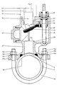
- FIGS. 1 to 4 each show in the upper part an identical embodiment of the tapping fitting according to the invention in different working positions.
- the lower part that is, in the area of the conduit 1
- four different fastening options are shown by way of example in FIGS. 1 to 4.
- the housing 20 with its elements is first explained with reference to the tapping device 50, while the different means for fastening the tapping fitting to the conduit 1 were only discussed in connection with this description.
- the tapping fitting consists of a housing 20, which is generally made of cast iron and has a housing connector 21 on the side of the conduit 1 and a bore, preferably a threaded bore 22, on the opposite side.
- the threaded bore 22 serves to receive the screw attachment 51 of a tapping device 50.
- the housing connector 21 in turn has a bore 21b which serves for the passage of the drilling head 54 of the tapping device 50 carried by the boring bar 53.
- the threaded bore 22 and the bore 21b of the housing connection piece 21 must therefore be arranged coaxially to one another and form the inlet and outlet opening of a tapping channel penetrating the housing 20, through which the drill with the drill rod 53 and the drill head 54 is guided up to the conduit 1.
- valve body consisting of valve flap carrier 30 and valve flap 33 projects into the mounting channel defined in this way.
- the valve flap carrier 30 is seated with a one-piece spindle nut 31 on the screw spindle 24, which runs axially parallel to the tapping channel or to the boring bar 53.
- the screw spindle 24, which is rotatable about its axis, is mounted at one end in a position bushing 25.
- the bearing bush 25 which is screwed into a threaded bore of the housing 20, is sealed off from the latter with an O-ring 25b, the screw spindle 24 passing through a dirt wiper 25a provided in the bush 25.
- the bearing bush 25 is also provided with a sealing and damping disk 27, against which the spindle nut 31 bears in the position according to FIG. 2.
- the lower end of the screw spindle 24 is designed as a bearing journal 24b and is rotatably mounted in a blind hole 28 of the housing 20.
- the valve flap carrier 30, which is height-adjustable by means of the screw spindle 24, has a drill opening 32 which allows the drill head 54 to pass through.
- This design measure makes the measures necessary for swiveling the solid valve body away from the tapping channel, which are necessary in known constructions, in a very simple manner.
- valve flap 33 fastened to the underside of the valve flap carrier 32 with screws 34 and pressure plate 35 is pivoted away.
- the valve flap itself consists of an elastomer with rubber-elastic properties, so that it has excellent sealing properties on the one hand and on the other hand itself forms an elastic joint 33d which enables pivoting away. Since this valve is only exposed to a few load changes anyway, a complex joint construction is unnecessary.
- valve flap 33 In the starting position, in which the tapping channel must be kept open for the insertion of the drill, the valve flap 33 lies with its outer free edge against a stop 29 projecting into the interior of the housing.
- valve flap carrier 30 In this position, the valve flap carrier 30 is to be raised with the aid of the screw spindle 24 until its spindle nut 31 rests with its end face on the sealing and damping disk 27 of the bearing bush 25.
- the valve flap carrier 30 When the valve flap carrier 30 is raised by this distance, the valve flap 33 disengages from the stop 29 and, due to the elasticity of the material, snaps into the position shown in FIG. 2.
- the housing 20 When drilling into the conduit 1 and in particular when pulling the drill 53/54 back into the position according to FIG. 2, the medium which is usually under pressure inside the conduit 1 enters the interior of the housing 20. B. to prevent tap water or gas, the housing 20 must be sealed from the outside. For this reason, the threaded bore 23a of the lateral housing connector 23 is closed with a sealing plug 40 and with an inserted sealing ring 40a in a liquid-tight or gas-tight manner. Likewise, the Screw attachment 51 of the tapping device 50 may be connected to the threaded bore 22 in a liquid-tight or gas-tight manner, if necessary using additional sealants.
- valve body consisting of the valve flap carrier 30 and the valve flap 33
- the valve body is brought into the lower position in FIG. 3 until the conical sealing surfaces 33a of the valve flap 33 bear tightly against the valve seat 21c of the bore 21b.
- the required sealing pressure is generated by means of the screw spindle 24 and transmitted to the valve flap 33 with the valve flap carrier 30.
- the valve flap 33 which is made of elastomer, is reinforced with a metal insert 33b.
- the threaded bore 22 of the housing 20 is closed with a sealing plug 41, a sealing ring 41 b inserted between the flange 41 a and the edge of the bore 22 ensuring the required liquid or gas tightness.
- a branch line can be screwed into the internal thread 23a of the bore 23b.
- connection between branch line and line pipe 1 is accomplished by lifting the valve flap support 30 with valve flaps 33 by means of the screw spindle 24.
- fastening hooks 33c which overlap the upper edge of the drill opening 32 with their driving lugs 33e, prevent the valve flap 33 from moving into the z. B. falls in position shown in Fig. 2.
- the valve flap carrier 30 can be retracted into the position shown in FIG. 2, the valve flap 33 extending parallel to the valve flap carrier 30 in the same way as in FIGS. 3 and 4, as in the illustration according to FIG. 2. The valve has thus performed its task until the connected branch line has to be shut off.
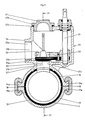
- an upper clamp part 10 is screwed onto the external thread 21a of the housing connector 21, which is supplemented with the lower clamp part 11 to form a clamp comprising the pipeline 1, the laterally projecting flanges 10b and 11a of the lower and upper clamp parts 10 and 11 are connected to each other by means of bolts 13, nuts 13a when using washers 13b.
- the inner surfaces of the upper and lower clamp parts 10, 11 are provided with a two-part sealing sleeve 12, which ensures a liquid or gas-tight seal in the area of the drill head 54 penetrating into the pipeline 1.
- a projection 10c which surrounds the drilling head 54 in a ring on the inner surface of the clamp 10, increases the sealing pressure in this section and thus improves the tightness.
- FIG. 2 A second embodiment of the fastening device is illustrated in FIG. 2, in which the housing connector 21 ' is widened to a flange 21'a even at its end facing the conduit 1, in the bores of which a bracket 14 comprising the conduit 1 is inserted with its threaded pins 14a provided at both ends, which is attached to the flange 21 'by nuts 14b using washers 14c a are fixed.
- a sealing ring 15 inserted on the underside of the flange ensures a liquid-tight or gas-tight closure of the bore 2 made in the conduit 1.
- FIG. 3 A possibility similar to the fastening form according to FIG. 1 is illustrated with FIG. 3.
- the housing stub 21 ' is connected in one piece to the upper clamp part 16, which is supplemented with the lower clamp part 17 to form a connecting clamp comprising the pipe 1.
- the upper and lower parts have radially projecting flange-like wedge extensions 16a, 17a, on which wedge brackets 1 are opened. This screwless connection is particularly suitable for use in civil engineering.
- the housing connector 21 ′′′ can also be equipped with a welding shoulder 19 which, as indicated by the welding seam 19a in FIG. 4, is permanently connected to the conduit 1.
Landscapes
- Engineering & Computer Science (AREA)
- General Engineering & Computer Science (AREA)
- Mechanical Engineering (AREA)
- Branch Pipes, Bends, And The Like (AREA)
- Valve Housings (AREA)
- Quick-Acting Or Multi-Walled Pipe Joints (AREA)
- Pharmaceuticals Containing Other Organic And Inorganic Compounds (AREA)
- Percussion Or Vibration Massage (AREA)
- Pipe Accessories (AREA)
Priority Applications (1)
| Application Number | Priority Date | Filing Date | Title |
|---|---|---|---|
| AT90107199T ATE86025T1 (de) | 1989-04-18 | 1990-04-17 | Anbohrarmatur. |
Applications Claiming Priority (2)
| Application Number | Priority Date | Filing Date | Title |
|---|---|---|---|
| DE3912669A DE3912669A1 (de) | 1989-04-18 | 1989-04-18 | Anbohrarmatur |
| DE3912669 | 1989-04-18 |
Publications (3)
| Publication Number | Publication Date |
|---|---|
| EP0393560A2 true EP0393560A2 (fr) | 1990-10-24 |
| EP0393560A3 EP0393560A3 (fr) | 1991-11-06 |
| EP0393560B1 EP0393560B1 (fr) | 1993-02-24 |
Family
ID=6378900
Family Applications (1)
| Application Number | Title | Priority Date | Filing Date |
|---|---|---|---|
| EP90107199A Expired - Lifetime EP0393560B1 (fr) | 1989-04-18 | 1990-04-17 | Appareil de perçage |
Country Status (4)
| Country | Link |
|---|---|
| EP (1) | EP0393560B1 (fr) |
| AT (1) | ATE86025T1 (fr) |
| DD (1) | DD293759A5 (fr) |
| DE (2) | DE3912669A1 (fr) |
Cited By (10)
| Publication number | Priority date | Publication date | Assignee | Title |
|---|---|---|---|---|
| GR900100398A (el) * | 1989-05-24 | 1991-10-10 | Ind Pipe Systems Pty Lt | Βρυση/βαλβιδα. |
| EP0580222A1 (fr) * | 1992-07-24 | 1994-01-26 | Polva Pipelife B.V. | Raccord de dérivation pour tuyauterie en matière thermoplastique |
| AU650633B2 (en) * | 1989-11-22 | 1994-06-30 | Milnes Pty. Limited | Tapping saddle |
| EP0709614A1 (fr) * | 1994-10-27 | 1996-05-01 | Automobiles Peugeot | Dispositif de perçage d'un corps cylindrique d'un amortisseur de véhicule automobile |
| NL9401549A (nl) * | 1994-09-23 | 1996-05-01 | Wavin Bv | Werkwijze en inrichting voor het maken van een opening in een onder druk verkerende buisleiding. |
| FR2729207A1 (fr) * | 1995-01-05 | 1996-07-12 | Ortino Sebastien | Raccord de derivation montable sur une conduite d'eau en charge |
| DE10109975A1 (de) * | 2001-03-01 | 2002-09-12 | Peter Pillmann | Füllvorrichtung für Rohrnetze |
| EP2339219A1 (fr) * | 2009-12-22 | 2011-06-29 | Friatec Aktiengesellschaft | Appareil de perçage |
| EP2520842A1 (fr) * | 2011-05-03 | 2012-11-07 | Pipelife Nederland B.V. | Dispositif de bonbout avec soupape de libération de pression adaptable pour tuyau en plastique |
| CN104154369A (zh) * | 2014-07-30 | 2014-11-19 | 无锡华毅管道有限公司 | 内衬式预应力钢筒混凝土管开孔装置及开孔方法 |
Families Citing this family (1)
| Publication number | Priority date | Publication date | Assignee | Title |
|---|---|---|---|---|
| DE4202237C2 (de) * | 1992-01-28 | 1996-09-12 | Bopp & Reuther Armaturen | Anbohrgerät zum Herstellen eines Abgangs an einer unter Druck stehenden Leitung |
Citations (3)
| Publication number | Priority date | Publication date | Assignee | Title |
|---|---|---|---|---|
| DE1188387B (de) * | 1962-02-17 | 1965-03-04 | Bopp & Reuther Gmbh | Ventilanbohrschelle fuer unter Druck stehende Rohrleitungen mit einem Haupt- und einem Hilfsventil |
| LU54175A1 (fr) * | 1966-08-05 | 1967-11-22 | ||
| DE2123539A1 (fr) * | 1971-05-12 | 1972-11-23 |
Family Cites Families (2)
| Publication number | Priority date | Publication date | Assignee | Title |
|---|---|---|---|---|
| DE1153591B (de) * | 1958-06-03 | 1963-08-29 | Schmitz & Co J | Anbohrschelle fuer unter Druck stehende Rohrleitungen |
| US3119579A (en) * | 1960-09-23 | 1964-01-28 | Litton Systems Inc | Balloon construction |
-
1989
- 1989-04-18 DE DE3912669A patent/DE3912669A1/de active Granted
-
1990
- 1990-04-17 DE DE9090107199T patent/DE59000906D1/de not_active Expired - Fee Related
- 1990-04-17 EP EP90107199A patent/EP0393560B1/fr not_active Expired - Lifetime
- 1990-04-17 AT AT90107199T patent/ATE86025T1/de not_active IP Right Cessation
- 1990-04-18 DD DD90339854A patent/DD293759A5/de not_active IP Right Cessation
Patent Citations (3)
| Publication number | Priority date | Publication date | Assignee | Title |
|---|---|---|---|---|
| DE1188387B (de) * | 1962-02-17 | 1965-03-04 | Bopp & Reuther Gmbh | Ventilanbohrschelle fuer unter Druck stehende Rohrleitungen mit einem Haupt- und einem Hilfsventil |
| LU54175A1 (fr) * | 1966-08-05 | 1967-11-22 | ||
| DE2123539A1 (fr) * | 1971-05-12 | 1972-11-23 |
Cited By (11)
| Publication number | Priority date | Publication date | Assignee | Title |
|---|---|---|---|---|
| GR900100398A (el) * | 1989-05-24 | 1991-10-10 | Ind Pipe Systems Pty Lt | Βρυση/βαλβιδα. |
| AU650633B2 (en) * | 1989-11-22 | 1994-06-30 | Milnes Pty. Limited | Tapping saddle |
| EP0580222A1 (fr) * | 1992-07-24 | 1994-01-26 | Polva Pipelife B.V. | Raccord de dérivation pour tuyauterie en matière thermoplastique |
| BE1006081A3 (fr) * | 1992-07-24 | 1994-05-10 | Draka Polva Bv | Raccord de derivation pour tuyauterie en matiere thermoplastique. |
| NL9401549A (nl) * | 1994-09-23 | 1996-05-01 | Wavin Bv | Werkwijze en inrichting voor het maken van een opening in een onder druk verkerende buisleiding. |
| EP0709614A1 (fr) * | 1994-10-27 | 1996-05-01 | Automobiles Peugeot | Dispositif de perçage d'un corps cylindrique d'un amortisseur de véhicule automobile |
| FR2729207A1 (fr) * | 1995-01-05 | 1996-07-12 | Ortino Sebastien | Raccord de derivation montable sur une conduite d'eau en charge |
| DE10109975A1 (de) * | 2001-03-01 | 2002-09-12 | Peter Pillmann | Füllvorrichtung für Rohrnetze |
| EP2339219A1 (fr) * | 2009-12-22 | 2011-06-29 | Friatec Aktiengesellschaft | Appareil de perçage |
| EP2520842A1 (fr) * | 2011-05-03 | 2012-11-07 | Pipelife Nederland B.V. | Dispositif de bonbout avec soupape de libération de pression adaptable pour tuyau en plastique |
| CN104154369A (zh) * | 2014-07-30 | 2014-11-19 | 无锡华毅管道有限公司 | 内衬式预应力钢筒混凝土管开孔装置及开孔方法 |
Also Published As
| Publication number | Publication date |
|---|---|
| DD293759A5 (de) | 1991-09-12 |
| DE3912669C2 (fr) | 1991-05-08 |
| EP0393560A3 (fr) | 1991-11-06 |
| DE3912669A1 (de) | 1990-10-25 |
| ATE86025T1 (de) | 1993-03-15 |
| DE59000906D1 (de) | 1993-04-01 |
| EP0393560B1 (fr) | 1993-02-24 |
Similar Documents
| Publication | Publication Date | Title |
|---|---|---|
| DE3100037C2 (fr) | ||
| EP0069240A2 (fr) | Garniture pour un dispositif de traitement d'une matière passant à travers un conduit | |
| EP0393560B1 (fr) | Appareil de perçage | |
| EP0305821B1 (fr) | Dispositif pour fermer l'embranchement d'un tube | |
| DE3830395C1 (en) | Boring fitting | |
| EP0884506B1 (fr) | Raccorderie, notamment clapet de réglage et d'arrêt | |
| EP1866050B1 (fr) | Dispositif filtrant | |
| DE4239573C2 (de) | Anbohrarmatur für unter Mediumdruck stehende Rohrleitungen | |
| DE202006015675U1 (de) | Bolzenverbindung zwischen Absperrscheibe und Spindelmutter einer Absperrarmatur | |
| EP1030289A2 (fr) | Dispositif de support pour un capteur | |
| EP1793150B1 (fr) | Dispositif d'arrêt, notamment pour conduites sous pression | |
| EP1258662B1 (fr) | Dispositif d'arrêt de fluide dans un conduit par un corps de fermeture sphérique | |
| DE2918555A1 (de) | Anbohrschelle | |
| DE4010177C2 (de) | Verfahren und Ventil zum Entlüften einer Rohrleitung | |
| DE3119579A1 (de) | Anbohrarmatur | |
| EP3683367B1 (fr) | Agencement de montage de lavabo ainsi que procédé d'assemblage d'un agencement de montage de lavabo | |
| EP0314823A1 (fr) | Soupape avec couvercle sans vis | |
| DE102007004717B3 (de) | Anschlussarmatur für eine flüssigkeitsführende Anordnung, insbesondere eine Heizkörperanordnung | |
| DE2636965C3 (de) | Anbohrvorrichtung für ein unter Druck stehendes Rohr | |
| DE4039353C1 (en) | Closing of damaged plastics pipe - involves plug screwed into side of pipe from housing fitted on outside | |
| DE202006005369U1 (de) | Absperrarmatur | |
| DE10213803B4 (de) | Anbohrsystem für Hausanschlussleitungen | |
| DE102012003647B4 (de) | Regulierschraube aus Kunststoff zum Justieren von Durchflußmessern sowie Durchflußmesser mit einer Regulierschraube | |
| DE19751198B4 (de) | Verfahren und Vorrichtung zum Absperren einer Rohrleitung | |
| DE3513060A1 (de) | Klappenventil |
Legal Events
| Date | Code | Title | Description |
|---|---|---|---|
| PUAI | Public reference made under article 153(3) epc to a published international application that has entered the european phase |
Free format text: ORIGINAL CODE: 0009012 |
|
| AK | Designated contracting states |
Kind code of ref document: A2 Designated state(s): AT CH DE FR GB LI |
|
| 17P | Request for examination filed |
Effective date: 19901219 |
|
| PUAL | Search report despatched |
Free format text: ORIGINAL CODE: 0009013 |
|
| AK | Designated contracting states |
Kind code of ref document: A3 Designated state(s): AT CH DE FR GB LI |
|
| 17Q | First examination report despatched |
Effective date: 19920729 |
|
| GRAA | (expected) grant |
Free format text: ORIGINAL CODE: 0009210 |
|
| AK | Designated contracting states |
Kind code of ref document: B1 Designated state(s): AT CH DE FR GB LI |
|
| REF | Corresponds to: |
Ref document number: 86025 Country of ref document: AT Date of ref document: 19930315 Kind code of ref document: T |
|
| ET | Fr: translation filed | ||
| GBT | Gb: translation of ep patent filed (gb section 77(6)(a)/1977) |
Effective date: 19930302 |
|
| REF | Corresponds to: |
Ref document number: 59000906 Country of ref document: DE Date of ref document: 19930401 |
|
| PLBE | No opposition filed within time limit |
Free format text: ORIGINAL CODE: 0009261 |
|
| STAA | Information on the status of an ep patent application or granted ep patent |
Free format text: STATUS: NO OPPOSITION FILED WITHIN TIME LIMIT |
|
| 26N | No opposition filed | ||
| PGFP | Annual fee paid to national office [announced via postgrant information from national office to epo] |
Ref country code: CH Payment date: 19950215 Year of fee payment: 6 |
|
| PGFP | Annual fee paid to national office [announced via postgrant information from national office to epo] |
Ref country code: FR Payment date: 19950317 Year of fee payment: 6 |
|
| PGFP | Annual fee paid to national office [announced via postgrant information from national office to epo] |
Ref country code: GB Payment date: 19950404 Year of fee payment: 6 |
|
| PGFP | Annual fee paid to national office [announced via postgrant information from national office to epo] |
Ref country code: AT Payment date: 19950420 Year of fee payment: 6 |
|
| PG25 | Lapsed in a contracting state [announced via postgrant information from national office to epo] |
Ref country code: GB Effective date: 19960417 Ref country code: AT Effective date: 19960417 |
|
| PG25 | Lapsed in a contracting state [announced via postgrant information from national office to epo] |
Ref country code: LI Effective date: 19960430 Ref country code: CH Effective date: 19960430 |
|
| GBPC | Gb: european patent ceased through non-payment of renewal fee |
Effective date: 19960417 |
|
| REG | Reference to a national code |
Ref country code: CH Ref legal event code: PL |
|
| PG25 | Lapsed in a contracting state [announced via postgrant information from national office to epo] |
Ref country code: FR Effective date: 19961227 |
|
| REG | Reference to a national code |
Ref country code: FR Ref legal event code: ST |
|
| PGFP | Annual fee paid to national office [announced via postgrant information from national office to epo] |
Ref country code: DE Payment date: 20010525 Year of fee payment: 12 |
|
| PG25 | Lapsed in a contracting state [announced via postgrant information from national office to epo] |
Ref country code: DE Free format text: LAPSE BECAUSE OF NON-PAYMENT OF DUE FEES Effective date: 20021101 |