EP0393560A2 - Tapping apparatus - Google Patents
Tapping apparatus Download PDFInfo
- Publication number
- EP0393560A2 EP0393560A2 EP90107199A EP90107199A EP0393560A2 EP 0393560 A2 EP0393560 A2 EP 0393560A2 EP 90107199 A EP90107199 A EP 90107199A EP 90107199 A EP90107199 A EP 90107199A EP 0393560 A2 EP0393560 A2 EP 0393560A2
- Authority
- EP
- European Patent Office
- Prior art keywords
- valve flap
- housing
- conduit
- drill
- tapping
- Prior art date
- Legal status (The legal status is an assumption and is not a legal conclusion. Google has not performed a legal analysis and makes no representation as to the accuracy of the status listed.)
- Granted
Links
Images


Classifications
-
- F—MECHANICAL ENGINEERING; LIGHTING; HEATING; WEAPONS; BLASTING
- F16—ENGINEERING ELEMENTS AND UNITS; GENERAL MEASURES FOR PRODUCING AND MAINTAINING EFFECTIVE FUNCTIONING OF MACHINES OR INSTALLATIONS; THERMAL INSULATION IN GENERAL
- F16L—PIPES; JOINTS OR FITTINGS FOR PIPES; SUPPORTS FOR PIPES, CABLES OR PROTECTIVE TUBING; MEANS FOR THERMAL INSULATION IN GENERAL
- F16L41/00—Branching pipes; Joining pipes to walls
- F16L41/04—Tapping pipe walls, i.e. making connections through the walls of pipes while they are carrying fluids; Fittings therefor
- F16L41/06—Tapping pipe walls, i.e. making connections through the walls of pipes while they are carrying fluids; Fittings therefor making use of attaching means embracing the pipe
Definitions
- the invention relates to a tapping fitting of the type specified in the preamble of the main claim.
- tapping fittings serve to lead a liquid or gaseous medium pipe, z. B. a water pipe to provide a hole for a branch line.
- the housing of the tapping fitting remains as a branch housing between the conduit and branch line.
- This housing which can be permanently connected to the conduit, therefore has, on the one hand, a tapping channel for inserting and guiding the drill and, on the other hand, a closable connecting piece for the branch line.
- the housing of the fitting must be designed so that no media leakage occurs during the production of the hole and especially when withdrawing the drill. For this reason, there is a manually operable one in the tapping channel between its inlet and outlet opening Valve is provided with which, in particular, the outlet opening and thus the bore made in the conduit can be closed until the branch line is connected.
- valve flap carrier of such a valve is consequently only in use for a comparatively short time, while in operation, that is to say after the branch line has been connected, it only serves to shut off the branch line.
- valve flap carrier can therefore be constructed relatively simply per se.
- a tapping fitting of the type in question in which a valve plate is provided as a valve body which can be raised by means of a screw spindle and thereby pivoted about the axis of the screw spindle.
- a screw-shaped guide groove is necessary, in which the valve disk engages with a guide cam.
- a pivotable valve flap is provided here as the valve body.
- the valve flap is actuated by means of a toothed rack driven by the screw spindle, which meshes with a toothed pinion provided on the valve flap.
- the present invention is therefore based on the object of simplifying the tapping fitting specified in the preamble of the main claim in such a way that it can be produced inexpensively with sufficient sealing and simple handling and ensures reliable operation.
- valve body namely a support that can be pushed forward by means of the screw spindle, to which a valve flap made of flexible material is attached as a sealing element, which flap can be removed from the tapping channel without the use of gears, joints or Like. Can be pivoted thanks to their material properties.
- the latter is provided with a drill opening corresponding to the drill head cross section, which is sealed by the latter itself when the outlet opening is closed by the valve flap.
- an elastomer is suitable as the valve flap material, in which a metal insert is integrated for stiffening.
- Claim 3 provided with fastening hooks which fix the valve flap on the valve flap carrier after the first actuation.
- Claims 6-9 relate to the means for fastening the housing to the conduit.
- FIGS. 1 to 4 each show in the upper part an identical embodiment of the tapping fitting according to the invention in different working positions.
- the lower part that is, in the area of the conduit 1
- four different fastening options are shown by way of example in FIGS. 1 to 4.
- the housing 20 with its elements is first explained with reference to the tapping device 50, while the different means for fastening the tapping fitting to the conduit 1 were only discussed in connection with this description.
- the tapping fitting consists of a housing 20, which is generally made of cast iron and has a housing connector 21 on the side of the conduit 1 and a bore, preferably a threaded bore 22, on the opposite side.
- the threaded bore 22 serves to receive the screw attachment 51 of a tapping device 50.
- the housing connector 21 in turn has a bore 21b which serves for the passage of the drilling head 54 of the tapping device 50 carried by the boring bar 53.
- the threaded bore 22 and the bore 21b of the housing connection piece 21 must therefore be arranged coaxially to one another and form the inlet and outlet opening of a tapping channel penetrating the housing 20, through which the drill with the drill rod 53 and the drill head 54 is guided up to the conduit 1.
- valve body consisting of valve flap carrier 30 and valve flap 33 projects into the mounting channel defined in this way.
- the valve flap carrier 30 is seated with a one-piece spindle nut 31 on the screw spindle 24, which runs axially parallel to the tapping channel or to the boring bar 53.
- the screw spindle 24, which is rotatable about its axis, is mounted at one end in a position bushing 25.
- the bearing bush 25 which is screwed into a threaded bore of the housing 20, is sealed off from the latter with an O-ring 25b, the screw spindle 24 passing through a dirt wiper 25a provided in the bush 25.
- the bearing bush 25 is also provided with a sealing and damping disk 27, against which the spindle nut 31 bears in the position according to FIG. 2.
- the lower end of the screw spindle 24 is designed as a bearing journal 24b and is rotatably mounted in a blind hole 28 of the housing 20.
- the valve flap carrier 30, which is height-adjustable by means of the screw spindle 24, has a drill opening 32 which allows the drill head 54 to pass through.
- This design measure makes the measures necessary for swiveling the solid valve body away from the tapping channel, which are necessary in known constructions, in a very simple manner.
- valve flap 33 fastened to the underside of the valve flap carrier 32 with screws 34 and pressure plate 35 is pivoted away.
- the valve flap itself consists of an elastomer with rubber-elastic properties, so that it has excellent sealing properties on the one hand and on the other hand itself forms an elastic joint 33d which enables pivoting away. Since this valve is only exposed to a few load changes anyway, a complex joint construction is unnecessary.
- valve flap 33 In the starting position, in which the tapping channel must be kept open for the insertion of the drill, the valve flap 33 lies with its outer free edge against a stop 29 projecting into the interior of the housing.
- valve flap carrier 30 In this position, the valve flap carrier 30 is to be raised with the aid of the screw spindle 24 until its spindle nut 31 rests with its end face on the sealing and damping disk 27 of the bearing bush 25.
- the valve flap carrier 30 When the valve flap carrier 30 is raised by this distance, the valve flap 33 disengages from the stop 29 and, due to the elasticity of the material, snaps into the position shown in FIG. 2.
- the housing 20 When drilling into the conduit 1 and in particular when pulling the drill 53/54 back into the position according to FIG. 2, the medium which is usually under pressure inside the conduit 1 enters the interior of the housing 20. B. to prevent tap water or gas, the housing 20 must be sealed from the outside. For this reason, the threaded bore 23a of the lateral housing connector 23 is closed with a sealing plug 40 and with an inserted sealing ring 40a in a liquid-tight or gas-tight manner. Likewise, the Screw attachment 51 of the tapping device 50 may be connected to the threaded bore 22 in a liquid-tight or gas-tight manner, if necessary using additional sealants.
- valve body consisting of the valve flap carrier 30 and the valve flap 33
- the valve body is brought into the lower position in FIG. 3 until the conical sealing surfaces 33a of the valve flap 33 bear tightly against the valve seat 21c of the bore 21b.
- the required sealing pressure is generated by means of the screw spindle 24 and transmitted to the valve flap 33 with the valve flap carrier 30.
- the valve flap 33 which is made of elastomer, is reinforced with a metal insert 33b.
- the threaded bore 22 of the housing 20 is closed with a sealing plug 41, a sealing ring 41 b inserted between the flange 41 a and the edge of the bore 22 ensuring the required liquid or gas tightness.
- a branch line can be screwed into the internal thread 23a of the bore 23b.
- connection between branch line and line pipe 1 is accomplished by lifting the valve flap support 30 with valve flaps 33 by means of the screw spindle 24.
- fastening hooks 33c which overlap the upper edge of the drill opening 32 with their driving lugs 33e, prevent the valve flap 33 from moving into the z. B. falls in position shown in Fig. 2.
- the valve flap carrier 30 can be retracted into the position shown in FIG. 2, the valve flap 33 extending parallel to the valve flap carrier 30 in the same way as in FIGS. 3 and 4, as in the illustration according to FIG. 2. The valve has thus performed its task until the connected branch line has to be shut off.
- an upper clamp part 10 is screwed onto the external thread 21a of the housing connector 21, which is supplemented with the lower clamp part 11 to form a clamp comprising the pipeline 1, the laterally projecting flanges 10b and 11a of the lower and upper clamp parts 10 and 11 are connected to each other by means of bolts 13, nuts 13a when using washers 13b.
- the inner surfaces of the upper and lower clamp parts 10, 11 are provided with a two-part sealing sleeve 12, which ensures a liquid or gas-tight seal in the area of the drill head 54 penetrating into the pipeline 1.
- a projection 10c which surrounds the drilling head 54 in a ring on the inner surface of the clamp 10, increases the sealing pressure in this section and thus improves the tightness.
- FIG. 2 A second embodiment of the fastening device is illustrated in FIG. 2, in which the housing connector 21 ' is widened to a flange 21'a even at its end facing the conduit 1, in the bores of which a bracket 14 comprising the conduit 1 is inserted with its threaded pins 14a provided at both ends, which is attached to the flange 21 'by nuts 14b using washers 14c a are fixed.
- a sealing ring 15 inserted on the underside of the flange ensures a liquid-tight or gas-tight closure of the bore 2 made in the conduit 1.
- FIG. 3 A possibility similar to the fastening form according to FIG. 1 is illustrated with FIG. 3.
- the housing stub 21 ' is connected in one piece to the upper clamp part 16, which is supplemented with the lower clamp part 17 to form a connecting clamp comprising the pipe 1.
- the upper and lower parts have radially projecting flange-like wedge extensions 16a, 17a, on which wedge brackets 1 are opened. This screwless connection is particularly suitable for use in civil engineering.
- the housing connector 21 ′′′ can also be equipped with a welding shoulder 19 which, as indicated by the welding seam 19a in FIG. 4, is permanently connected to the conduit 1.
Abstract
Description
Die Erfindung betrifft eine Anbohrarmatur der im Oberbegriff des Hauptanspruchs angegebenen Art.The invention relates to a tapping fitting of the type specified in the preamble of the main claim.
Solche Anbohrarmaturen dienen dazu, ein ein flüssiges oder gasförmiges Medium führendes Leitungsrohr, z. B. ein Wasserrohr, mit einer Bohrung für eine Zweigleitung zu versehen. Hierbei verbleibt das Gehäuse der Anbohrarmatur als Abzweiggehäuse zwischen Leitungsrohr und Zweigleitung.Such tapping fittings serve to lead a liquid or gaseous medium pipe, z. B. a water pipe to provide a hole for a branch line. Here, the housing of the tapping fitting remains as a branch housing between the conduit and branch line.
Dieses mit dem Leitungsrohr bleibend verbindbare Gehäuse weist darum einerseits einen Anbohrkanal zum Einbringen und Führen des Bohrers und andererseits einen verschließbaren Anschlußstutzen für die Zweigleitung auf.This housing, which can be permanently connected to the conduit, therefore has, on the one hand, a tapping channel for inserting and guiding the drill and, on the other hand, a closable connecting piece for the branch line.
Da die Zweigleitung häufig in einem Zeitpunkt angeschlossen werden muß, in welchem das Leitungsrohr bereits das Medium, z. B. Wasser, führt, muß das Gehäuse der Anbauarmatur so ausgebildet sein, daß bei der Herstellung der Bohrung und insbesondere beim Zurückziehen des Bohrers kein Mediumsaustritt erfolgt. Aus diesem Grunde ist im Anbohrkanal zwischen dessen Ein- und Austrittsöffnung ein manuell betätigbares Ventil vorgesehen, mit welchem vor allem die Austrittsöffnung und damit die im Leitungsrohr hergestellte Bohrung solange verschlossen werden kann, bis die Zweigleitung angeschlossen ist.Since the branch line must often be connected at a time when the conduit is already the medium, for. B. water, leads, the housing of the fitting must be designed so that no media leakage occurs during the production of the hole and especially when withdrawing the drill. For this reason, there is a manually operable one in the tapping channel between its inlet and outlet opening Valve is provided with which, in particular, the outlet opening and thus the bore made in the conduit can be closed until the branch line is connected.
Der Ventilklappenträger eines derartigen Ventils ist folglich nur für eine vergleichsweise kurze Zeit im Einsatz, während er im Betrieb, also nach Anschluß der Zweigleitung, nur noch dem Absperren der Zweigleitung dient.The valve flap carrier of such a valve is consequently only in use for a comparatively short time, while in operation, that is to say after the branch line has been connected, it only serves to shut off the branch line.
Der Ventilklappenträger kann darum an sich relativ einfach aufgebaut sein.The valve flap carrier can therefore be constructed relatively simply per se.
Aus der DE-OS 2 123 539 ist eine Anbohrarmatur der in Betracht kommenden Gattung bekannt, bei welcher als Ventilkörper ein mittels einer Schraubspindel anhebbarer und hierbei um die Achse der Schraubspindel verschwenkbarer Ventilteller vorgesehen ist. Zur Erzeugung der Schwenkbewegung während des Ventiltellervorschubes ist eine schraubengangförmige Führungsnut notwendig, in welche der Ventilteller mit einer Führungsnocke eingreift. Diese Konstruktion ist hinsichtlich des Aufbaus und auch ihrer Funktion noch vergleichsweise aufwendig. Außerdem ist das Gehäuse relativ voluminös, da der weggeschwenkte Ventilteller zusätzlichen Raumbedarf hat.From DE-OS 2 123 539, a tapping fitting of the type in question is known, in which a valve plate is provided as a valve body which can be raised by means of a screw spindle and thereby pivoted about the axis of the screw spindle. To generate the swiveling movement during the valve disk advance, a screw-shaped guide groove is necessary, in which the valve disk engages with a guide cam. This construction is comparatively complex in terms of structure and also its function. In addition, the housing is relatively voluminous, since the valve plate swung away requires additional space.
Weniger Platzbedarf hat die Anbohrarmatur nach der DE-OS 31 19 579, von welcher die vorliegende Erfindung ausgeht. Als Ventilkörper ist hier eine schwenkbare Ventilklappe vorgesehen. Die Ventilklappe wird mittels einer von der Schraubspindel angetriebenen Zahnstange betätigt, welche in ein an der Ventilklappe vorgesehenes Zahnritzel eingreift. Auch diese Konstruktion ist noch zu aufwendig und wegen der ineinandergreifenden Verzahnungen, die offen im Inneren des vom Medium durchströmten Gehäuses liegen, störanfällig.The tapping fitting according to DE-OS 31 19 579, from which the present invention is based, takes up less space. A pivotable valve flap is provided here as the valve body. The valve flap is actuated by means of a toothed rack driven by the screw spindle, which meshes with a toothed pinion provided on the valve flap. This construction, too, is still too complex and prone to failure because of the interlocking teeth that lie open inside the housing through which the medium flows.
Der vorliegenden Erfindung liegt darum die Aufgabe zugrunde, die im Oberbegriff des Hauptanspruchs angegebene Anbohrarmatur so zu vereinfachen, daß sie bei ausreichender Abdichtung einfacher Handhabungen kostengünstig hergestellt werden kann und eine sichere Funktion gewährleistet.The present invention is therefore based on the object of simplifying the tapping fitting specified in the preamble of the main claim in such a way that it can be produced inexpensively with sufficient sealing and simple handling and ensures reliable operation.
Gelöst wird diese Aufgabe mit den im Kennzeichen des Hauptanspruchs angegebenen Merkmalen.This task is solved with the characteristics indicated in the characterizing part of the main claim.
Die Grundidee der Erfindung besteht darin, als Ventilkörper ein sehr einfach aufgebautes zweiteiliges Element zu verwenden, nämlich einen mittels der Schraubspindel vorschiebbaren Träger, an welchem als Dichtelement eine aus flexiblem Material bestehende Ventilklappe angebracht ist, welche aus dem Anbohrkanal ohne Verwendung von Zahnrädern, Gelenken oder dgl. dank ihrer Materialeigenschaft geschwenkt werden kann. Um den Durchtritt des Bohrers im Bereich des Ventilklappenträgers zu ermöglichen, ist dieser mit einer dem Bohrkopfquerschnitt entsprechenden Bohreröffnung versehen, welche bei durch die Ventilklappe verschlossener Austrittsöffnung durch letztere selbst abgedichtet ist.The basic idea of the invention is to use a very simply constructed two-part element as the valve body, namely a support that can be pushed forward by means of the screw spindle, to which a valve flap made of flexible material is attached as a sealing element, which flap can be removed from the tapping channel without the use of gears, joints or Like. Can be pivoted thanks to their material properties. In order to enable the drill to pass through in the region of the valve flap carrier, the latter is provided with a drill opening corresponding to the drill head cross section, which is sealed by the latter itself when the outlet opening is closed by the valve flap.
Wie mit Anspruch 2 angegeben ist, eignet sich als Ventilklappenmaterial ein Elastomer, in das zur Versteifung eine Metalleinlage integriert ist.As indicated with claim 2, an elastomer is suitable as the valve flap material, in which a metal insert is integrated for stiffening.
Um die Ventilklappe sicher von der Austrittsöffnung abheben zu können, ist diese gem. Anspruch 3 mit Befestigungshaken versehen, welche die Ventilklappe nach der ersten Betätigung am Ventilklappenträger festlegen.In order to be able to safely lift the valve flap out of the outlet opening, this is acc. Claim 3 provided with fastening hooks which fix the valve flap on the valve flap carrier after the first actuation.
Konstruktionsmaßnahmen zur Vereinfachung der Herstellung bei sicherer Funktion sind mit den Ansprüchen 4 und 5 angegeben.Design measures to simplify production with safe function are specified with claims 4 and 5.
Die Ansprüche 6 - 9 beziehen sich auf die Mittel zur Befestigung des Gehäuses an dem Leitungsrohr.Claims 6-9 relate to the means for fastening the housing to the conduit.
Im übrigen ist der Gegenstand der Erfindung anhand verschiedener Ausführungsbeispiele, die in den Figuren 1 bis 4 der Zeichnung dargestellt sind, nachstehend im einzelnen erläutert.Otherwise, the subject matter of the invention is explained in detail below using various exemplary embodiments which are illustrated in FIGS. 1 to 4 of the drawing.
In der Zeichnung zeigen:
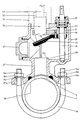
- Fig. 1 Axialschnitt einer erfindungsgemäßen Anbohrarmatur in der Ausgangsposition bei strichpunktiert angedeutetem Bohrer, wobei das Gehäuse mit dem Leitungsrohr mittels einer Schelle mit Schrauben verbunden ist,
- Fig. 2 Axialschnitt der erfindungsgemäßen Anbohrarmatur gemäß Fig. 1 in einer zweiten Position, in welcher der Bohrer zurückgezogen und der Ventilkörper geringfügig angehoben ist, wobei das Gehäuse mittels eines Bügels am Leitungsrohr befestigt ist,
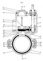
- Fig. 3 Axialschnitt der erfindungsgemäßen Anbohrarmatur gemäß Fig. 1 und 2 in einer Position, in welcher das Anbohrgerät entfernt, das Ventil geschlossen und das Gehäuse für den Anschluß der Zweigleitung vorbereitet ist, wobei das Gehäuse mit Keilbügeln und einer Schelle mit dem Leitungsrohr verbunden ist und
- Fig. 4 Schnitt längs der Linie IV-IV aus Fig. 3 der erfindungsgemäßen Anbohrarmatur, wobei das Gehäuse allerdings anders als nach Fig. 3 mit dem Leitungsrohr verschweißt ist.
- 1 axial section of a tapping fitting according to the invention in the starting position with a drill indicated by dash-dotted lines, the housing being connected to the conduit by means of a clamp with screws,
- 2 axial section of the tapping fitting according to the invention according to FIG. 1 in a second position, in which the drill is withdrawn and the valve body is slightly raised, the housing being fastened to the conduit by means of a bracket,
- Fig. 3 axial section of the tapping fitting according to FIGS. 1 and 2 in a position in which the tapping device is removed, the valve is closed and the housing is prepared for the connection of the branch line, the housing being connected to the conduit by means of wedge brackets and a clamp and
- Fig. 4 section along the line IV-IV of Fig. 3 of the tapping fitting according to the invention, the housing, however, differently than in Fig. 3 with the pipe is welded.
Die Figuren 1 bis 4 zeigen jeweils im oberen Teil ein identisches Ausführungsbeispiel der erfindungsgemäßen Anbohrarmatur in verschiedenen Arbeitspositionen. Im unteren Teil, also im Bereich des Leitungsrohres 1, sind in den Figuren 1 bis 4 vier verschiedene Befestigungsmöglichkeiten beispielhaft gezeigt.Figures 1 to 4 each show in the upper part an identical embodiment of the tapping fitting according to the invention in different working positions. In the lower part, that is, in the area of the
Zum besseren Verständnis von Aufbau und Arbeitsweise der Anbohrarmatur ist zunächst das Gehäuse 20 mit seinen Elementen unter Bezugnahme auf das Anbohrgerät 50 erläutert, während auf die unterschiedlichen Mittel zur Befestigung der Anbohrarmatur am Leitungsrohr 1 erst im Anschluß an diese Beschreibung im Zusammenhang eingegangen ist.For a better understanding of the structure and mode of operation of the tapping fitting, the
Die Anbohrarmatur besteht aus einem in der Regel aus Eisenguß hergestellten Gehäuse 20, das auf der Seite des Leitungsrohres 1 einen Gehäusestutzen 21 und auf der gegenüberliegenden Seite eine Bohrung, vorzugsweise eine Gewindebohrung, 22 besitzt. Die Gewindebohrung 22 dient der Aufnahme des Schraubansatzes 51 eines Anbohrgerätes 50. Der Gehäusestutzen 21 seinerseits weist eine Bohrung 21b auf, welche dem Durchtritt des von der Bohrstange 53 getragenen Bohrkopfes 54 des Anbohrgerätes 50 dient. Gewindebohrung 22 und Bohrung 21b des Gehäusestutzens 21 müssen darum koxial zueinander angeordnet sein und bilden Eintritts- und Austrittsöffnung eines das Gehäuse 20 durchsetzenden Anbohrkanales,durch welchen der Bohrer mit Bohrstange 53 und Bohrkopf 54 bis zum Leitungsrohr 1 hindurchgeführt wird.The tapping fitting consists of a
Innerhalb des Gehäuses 20 ragt in den so definierten Anbaukanal ein aus Ventilklappenträger 30 und Ventilklappe 33 bestehender Ventilkörper. Der Ventilklappenträger 30 sitzt mit einer einstückigen Spindelmutter 31 auf der Schraubspindel 24, welche achsparallel zum Anbohrkanal bzw. zur Bohrstange 53 verläuft. Die um ihre Achse verdrehbare Schraubspindel 24 ist einerends in einer Lagebüchse 25 gelagert. Zur Betätigung der Schraubspindel 24 ist diese mit einem Vierkant 24a versehen, auf welchen ein nicht dargestellter Betätigungshebel oder ein Betätigungsrad aufgesetzt werden kann. Die Lagerbüchse 25, die in eine Gewindebohrung des Gehäuses 20 eingeschraubt ist, ist gegenüber letzterem mit einem O-Ring 25b abgedichtet, wobei die Schraubenspindel 24 einem in der Büchse 25 vorgesehenen Schmutzabstreifer 25a durchsetzt. Der Lagerung der Schraubenspindel 24 innerhalb der Lagerbuchse 25 dienen Lagerringe 24c, zwischen welchen Dichtungsringe 26 angeordnet sind. Im Gehäuseinneren ist die Lagerbüchse 25 ferner mit einer Dicht- und Dämpfungsscheibe 27 versehen, an welcher die Spindelmutter 31 in der Position gemäß Fig. 2 anliegt.Within the
Das untere Ende der Schraubspindel 24 ist als Lagerzapfen 24b ausgebildet und in einem Sackloch 28 des Gehäuses 20 verdrehbar gelagert.The lower end of the
Der mittels der Schraubspindel 24 höhenverstellbare Ventilklappenträger 30 weist eine dem Durchtritt des Bohrkopfes 54 gestattende Bohreröffnung 32 auf. Durch diese Konstruktionsmaßnahme erübrigen sich in sehr einfacher Weise die bei bekannten Konstruktionen notwendigen Maßnahmen zum Wegschwenken des massiven Ventilkörpers aus dem Anbohrkanal.The
Bei der erfindungsgemäßen Konstruktion ist stattdessen die an der Unterseite des Ventilklappenträgers 32 mit Schrauben 34 und Druckplatte 35 befestigte Ventilklappe 33 weggeschwenkt. Die Ventilklappe selbst besteht aus einem Elastomer mit gummielastischen Eigenschaften, so daß sie einerseits hervorragende Dichteigenschaften hat und andererseits selbst ein das Wegschwenken ermöglichendes elastisches Gelenk 33d bildet. Da dieses Ventil ohnehin nur wenigen Lastwechseln ausgesetzt ist, ist eine aufwendige Gelenkkonstruktion überflüssig.In the construction according to the invention, instead, the
In der Ausgangsposition, in welcher der Anbohrkanal für das Einbringen des Bohrers offengehalten werden muß, liegt die Ventilklappe 33 mit ihrem äußeren freien Rand an einem in das Innere des Gehäuses ragenden Anschlag 29 kraftschlüssig an.In the starting position, in which the tapping channel must be kept open for the insertion of the drill, the valve flap 33 lies with its outer free edge against a
Nachdem, wie mit Fig. 1 angedeutet ist, im Leitungsrohr 1 mit dem Bohrkopf 54 die erforderliche Bohrung hergestellt ist, kann dieser in die in Fig. 2 angedeutete Position zurückgezogen werden, in welcher der Bohrkopf 54 von der Bohrkopfaufnahme 52 des Anbohrgerätes 50 aufgenommen wird.After the required bore has been made in the
In dieser Position ist der Ventilklappenträger 30 mit Hilfe der Schraubspindel 24 anzuheben, bis seine Spindelmutter 31 mit ihrer Stirnfläche an der Dicht- und Dämpfungsscheibe 27 der Lagerbüchse 25 anliegt. Bei Anheben des Ventilklappenträgers 30 um diese Wegstrecke gelangt die Ventilklappe 33 mit dem Anschlag 29 außer Eingriff und schnellt aufgrund der Materialelastizität in die in Fig. 2 gezeigte Lage.In this position, the
Beim Anbohren des Leitungsrohres 1 und insbesondere beim Zurückziehen des Bohrers 53/54 in die Position gemäß Fig. 2 gelangt das in der Regel innerhalb des Leitungsrohres 1 unter Druck stehende Medium in das Innere des Gehäuses 20. Um ein Austreten des Mediums, z. B. von Leitungswasser oder Gas, zu verhindern, muß das Gehäuse 20 gegenüber dem Außenbereich abgedichtet sein. Aus diesem Grund ist die Gewindebohrung 23a des seitlichen Gehäusestutzens 23 mit einem Verschlußstopfen 40 und mit eingelegten Dichtungsring 40a flüssigkeits- bzw. gasdicht verschlossen. Ebenso muß der Schraubansatz 51 des Anbohrgerätes 50 mit der Gewindebohrung 22 ggf. unter Verwendung weiterer Dichtmittel flüssigkeits- oder gasdicht verbunden sein.When drilling into the
Um das Anbohrgerät 50 entfernen und den Gehäusestutzen 23 öffnen zu können, ist ein Verschluß der Bohrung 21b des Gehäusestutzens 21 bzw. 21′, 21˝ oder 21 ‴ erforderlich.In order to remove the
Diese Anordnung ist mit der Darstellung gemäß Fig. 3 veranschaulicht. Durch Verdrehen der Schraubspindel 24 wird der Ventilkörper, bestehend aus Ventilklappenträger 30 und Ventilklappe 33, in die in Fig. 3 untere Position gebracht, bis die konischen Dichtflächen 33a der Ventilklappe 33 am Ventilsitz 21c der Bohrung 21b dichtend anliegen. Der erforderliche Dichtungsdruck wird mittels der Schraubspindel 24 erzeugt und mit dem Ventilklappenträger 30 auf die Ventilklappe 33 übertragen. Um eine gleichmäßige Kraftübertragung im Bereich der Bohreröffnung 32 zu gewährleisten, ist die aus Elastomer bestehende Ventilklappe 33 mit einer Metalleinlage 33b verstärkt.This arrangement is illustrated with the illustration according to FIG. 3. By turning the
Nach Entfernen des Anbohrgerätes 50 wird die Gewindebohrung 22 des Gehäuses 20 mit einem Verschußstopfen 41 verschlossen, wobei ein zwischen dem Flansch 41a und dem Rand der Bohrung 22 eingelegter Dichtungsring 41 b für die erforderliche Flüssigkeits- bzw. Gasdichheit sorgt.After removing the
Hierauf kann nach Entfernen des Stopfens 40 gemäß Fig. 1 und 2 eine nicht dargestellte Zweigleitung in das Innengewinde 23a der Bohrung 23b eingeschraubt werden.Then, after removing the
Die Verbindung zwischen Zweigleitung und Leitungsrohr 1 wird durch Anheben des Ventilklappenträgers 30 mit Ventilklappen 33 mittels der Schraubspindel 24 bewerkstelligt.The connection between branch line and
Wie der um 90° gedrehte Schnitt gemäß Fig. 4 verdeutlicht, verhindern Befestigungshaken 33c, welche mit ihren Mitnahmenasen 33e den oberen Rand der Bohreröffnung 32 übergreifen, daß die Ventilklappe 33 in die z. B. in Fig. 2 gezeigte Position zurückfällt. Der Ventilklappenträger 30 kann in die Fig. 2 gezeigte Position zurückgefahren werden, wobei sich die Ventilklappe 33 anders als bei der Darstellung gemäß Fig. 2 in gleicher Weise wie in Fig. 3 und 4 parallel zum Ventilklappenträger 30 erstreckt. Das Ventil hat damit bis zu einem etwaig notwendig werdenden Absperren der angeschlossenen Zweigleitung seine Aufgabe erfüllt.As illustrated by the section rotated through 90 ° according to FIG. 4, fastening hooks 33c, which overlap the upper edge of the drill opening 32 with their
Unterschiedliche Befestigungsmöglichkeiten der Anbohrarmatur sind jeweils in den Figuren 1 bis 4 veranschaulicht.Different fastening options for the tapping fitting are illustrated in FIGS. 1 to 4.
Bei der Ausführungsform gemäß Fig. 1 ist auf das Außengewinde 21a des Gehäusestutzens 21 ein Schellenoberteil 10 aufgeschraubt, daß mit dem Schellenunterteil 11 zu einer die Rohrleitung 1 umfassenden Schelle ergänzt wird, wobei die seitlich abstehenden aneinander anliegenden Flansche 10b und 11a der Schellenunter- und oberteile 10 und 11 mit Hilfe von Schraubbolzen 13, Muttern 13a bei Verwendung von Unterlegscheiben 13b miteinander verbunden sind.In the embodiment according to FIG. 1, an
Die Innenflächen der Schellenober- und unterteile 10, 11 sind mit einer zweigeteilten Dichtungsmanschette 12 versehen, welche für einen flüssigkeits- oder gasdichten Abschluß im Bereich des in die Rohrleitung 1 eindringenden Bohrkopfes 54 sorgt. Ein den Bohrkopf 54 ringförmig umgebender Vorsprung 10c auf der Innenfläche der Schelle 10 erhöht in diesem Abschnitt den Dichtungsdruck und verbessert damit die Dichtheit.The inner surfaces of the upper and
Eine zweite Auführungsform der Befestigungseinrichtung ist in Fg. 2 veranschaulicht, bei welcher der Gehäusestutzen 21′ selbst an seinem dem Leitungsrohr 1 zugewandten Ende zu einem Flansch 21′a verbreitert ist, in dessen Bohrungen ein das Leitungsrohr 1 umfassender Bügel 14 mit seinen beidendig vorgesehenen Gewindezapfen 14a eingesetzt ist, welche mit Muttern 14b unter Verwendung von Unterlegscheiben 14c an dem Flansch 21′a festgelegt sind. Bei dieser Ausführungsform sorgt ein an der Flanschunterseite eingelegter Dichtring 15 für einen flüssigkeits- oder gasdichten Abschluß der in das Leitungsrohr 1 eingebrachten Bohrung 2.A second embodiment of the fastening device is illustrated in FIG. 2, in which the housing connector 21 ' is widened to a flange 21'a even at its end facing the
Eine der Befestigungsform gemäß Fig. 1 ähnliche Möglichkeit ist mit Fig. 3 veranschaulicht. Der Gehäusestutzen 21˝ ist hier einstückig mit dem Schellenoberteil 16 verbunden, das mit dem Schellenunterteil 17 zu einer das Rohr 1 umfassenden Verbindungsschelle ergänzt wird. Ober- und Unterteil besitzen radial abstehende flanschartige Keilansätze 16a, 17a, auf welche Keilbügel 1 aufgeschlagen sind. Diese schraubenlose Verbindung ist insbesondere für den Einsatz im Tiefbau geeignet.A possibility similar to the fastening form according to FIG. 1 is illustrated with FIG. 3. The housing stub 21 'is connected in one piece to the
Nicht zuletzt kann auch der Gehäusestutzen 21‴ mit einem Schweißansatz 19 ausgestattet sein, der, wie mit der Schweißnaht 19a in Fig. 4 angedeutet ist, mit dem Leitungsrohr 1 unlösbar verbunden ist.Last but not least, the
- 1 Leitungsrohr1 conduit
- 2 Bohrung2 holes
-
10 Schellenoberteil
- 10a Stutzenaufnahme
- 10b Flansch
- 10C Ringvorsprung
- 10a socket adapter
- 10b flange
- 10C ring projection
-
11 Schellenunterteil
- 11a Flansch
- 11a flange
- 12 Dichtmanschette12 sealing sleeve
-
13 Schraubbolzen
- 13a Mutter
- 13b Unterlegscheibe
- 13a mother
- 13b washer
-
14 Bügel
- 14a Gewindezapfen
- 14b Muttern
- 14c Unterlegscheiben
- 14a threaded pin
- 14b nuts
- 14c washers
- 15 Dichtring15 sealing ring
-
16 Schellenoberteil
- 16a flanschartiger Keilansatz
- 16a flange-like wedge attachment
-
17 Schellenunterteil
- 17a flanschartiger Keilansatz
- 17a flange-like wedge attachment
- 18 Keilbügel18 wedge brackets
-
19 Schweißansatz
- 19a Schweißnaht
- 19a weld
- 20 Gehäuse20 housing
-
21, 21′
- 21˝ Gehäusestutzen
- 21‴
- 21a Außengewinde
- 21b Bohrung
- 21c Ventilsitz
- 21′a Flansch
- 21˝ housing connector
- 21 ‴
- 21a external thread
- 21b bore
- 21c valve seat
- 21′a flange
- 22 Gewindebohrung22 threaded hole
-
23 Gehäusestutzen
- 23a Innengewinde
- 23b Bohrung
- 23a internal thread
- 23b bore
-
24 Schraubspindel
- 24a Vierkant
- 24b Lagerzapfen
- 24c Lager- und Dichtringe
- 24d Gewinde
- 24a square
- 24b journal
- 24c bearing and sealing rings
- 24d thread
-
25 Lagerbüchse
- 25a Schmutzabstreifer
- 25b Dichtungs-O-Ring
- 25a dirt scraper
- 25b seal o-ring
- 26 Dichtungsringe26 sealing rings
- 27 Dicht- und Dämpfungsscheibe27 Sealing and damping disc
- 28 Sackloch28 blind hole
- 29 Anschlag29 stop
- 30 Ventilklappenträger30 valve flap carrier
- 31 Spindelmutter31 spindle nut
- 32 Bohreröffnung32 drill opening
-
33 Ventilklappe
- 33a Dichtfläche
- 33b Metallanlage
- 33c Befestigungshaken
- 33d elastisches Gelenk
- 33e Mitnahmenasen
- 33a sealing surface
- 33b metal plant
- 33c mounting hook
- 33d elastic joint
- 33e take-away noses
- 34 Schrauben34 screws
- 35 Druckplatte35 pressure plate
-
40 Verschußstopfen
- 40a Dichtring
- 40a sealing ring
-
41 Verschlußstopfen
- 41a Flansch
- 41b Dichtring
- 41a flange
- 41b sealing ring
- 50 Anbohrgerät50 tapping device
- 51 Schraubansatz51 screw attachment
- 52 Bohrkopfaufnahme52 drill head holder
- 53 Bohrstange53 boring bar
- 54 Bohrkopf54 drill head
Claims (8)
Priority Applications (1)
| Application Number | Priority Date | Filing Date | Title |
|---|---|---|---|
| AT90107199T ATE86025T1 (en) | 1989-04-18 | 1990-04-17 | DRILLING FITTING. |
Applications Claiming Priority (2)
| Application Number | Priority Date | Filing Date | Title |
|---|---|---|---|
| DE3912669 | 1989-04-18 | ||
| DE3912669A DE3912669A1 (en) | 1989-04-18 | 1989-04-18 | TAPPING FITTING |
Publications (3)
| Publication Number | Publication Date |
|---|---|
| EP0393560A2 true EP0393560A2 (en) | 1990-10-24 |
| EP0393560A3 EP0393560A3 (en) | 1991-11-06 |
| EP0393560B1 EP0393560B1 (en) | 1993-02-24 |
Family
ID=6378900
Family Applications (1)
| Application Number | Title | Priority Date | Filing Date |
|---|---|---|---|
| EP90107199A Expired - Lifetime EP0393560B1 (en) | 1989-04-18 | 1990-04-17 | Tapping apparatus |
Country Status (4)
| Country | Link |
|---|---|
| EP (1) | EP0393560B1 (en) |
| AT (1) | ATE86025T1 (en) |
| DD (1) | DD293759A5 (en) |
| DE (2) | DE3912669A1 (en) |
Cited By (10)
| Publication number | Priority date | Publication date | Assignee | Title |
|---|---|---|---|---|
| GR900100398A (en) * | 1989-05-24 | 1991-10-10 | Ind Pipe Systems Pty Lt | Tap/valve |
| EP0580222A1 (en) * | 1992-07-24 | 1994-01-26 | Polva Pipelife B.V. | Branch coupling for a thermoplastic pipeline |
| AU650633B2 (en) * | 1989-11-22 | 1994-06-30 | Milnes Pty. Limited | Tapping saddle |
| EP0709614A1 (en) * | 1994-10-27 | 1996-05-01 | Automobiles Peugeot | Tapping device for a cylindrical body of a shock damper for a motor vehicle |
| NL9401549A (en) * | 1994-09-23 | 1996-05-01 | Wavin Bv | Method and device for making an opening in a pipeline which is subjected to pressure |
| FR2729207A1 (en) * | 1995-01-05 | 1996-07-12 | Ortino Sebastien | Branch pipe coupling for water pipe under pressure |
| DE10109975A1 (en) * | 2001-03-01 | 2002-09-12 | Peter Pillmann | Filling device for telecommunication conduit system, consists of detachable muff with valve system located in hole in conduit |
| EP2339219A1 (en) * | 2009-12-22 | 2011-06-29 | Friatec Aktiengesellschaft | Tapping fitting |
| EP2520842A1 (en) * | 2011-05-03 | 2012-11-07 | Pipelife Nederland B.V. | Top-piece device with a retrofittable pressure relief valve for a plastic pipe |
| CN104154369A (en) * | 2014-07-30 | 2014-11-19 | 无锡华毅管道有限公司 | Punching device and punching method for lined PCCP (prestressed concrete cylinder pipe) |
Families Citing this family (1)
| Publication number | Priority date | Publication date | Assignee | Title |
|---|---|---|---|---|
| DE4202237C2 (en) * | 1992-01-28 | 1996-09-12 | Bopp & Reuther Armaturen | Tapping device for producing an outlet on a pressurized line |
Citations (3)
| Publication number | Priority date | Publication date | Assignee | Title |
|---|---|---|---|---|
| DE1188387B (en) * | 1962-02-17 | 1965-03-04 | Bopp & Reuther Gmbh | Valve saddle for pipes under pressure with a main and an auxiliary valve |
| LU54175A1 (en) * | 1966-08-05 | 1967-11-22 | ||
| DE2123539A1 (en) * | 1971-05-12 | 1972-11-23 |
Family Cites Families (2)
| Publication number | Priority date | Publication date | Assignee | Title |
|---|---|---|---|---|
| DE1153591B (en) * | 1958-06-03 | 1963-08-29 | Schmitz & Co J | Tapping saddle for pipes under pressure |
| US3119579A (en) * | 1960-09-23 | 1964-01-28 | Litton Systems Inc | Balloon construction |
-
1989
- 1989-04-18 DE DE3912669A patent/DE3912669A1/en active Granted
-
1990
- 1990-04-17 EP EP90107199A patent/EP0393560B1/en not_active Expired - Lifetime
- 1990-04-17 DE DE9090107199T patent/DE59000906D1/en not_active Expired - Fee Related
- 1990-04-17 AT AT90107199T patent/ATE86025T1/en not_active IP Right Cessation
- 1990-04-18 DD DD90339854A patent/DD293759A5/en not_active IP Right Cessation
Patent Citations (3)
| Publication number | Priority date | Publication date | Assignee | Title |
|---|---|---|---|---|
| DE1188387B (en) * | 1962-02-17 | 1965-03-04 | Bopp & Reuther Gmbh | Valve saddle for pipes under pressure with a main and an auxiliary valve |
| LU54175A1 (en) * | 1966-08-05 | 1967-11-22 | ||
| DE2123539A1 (en) * | 1971-05-12 | 1972-11-23 |
Cited By (11)
| Publication number | Priority date | Publication date | Assignee | Title |
|---|---|---|---|---|
| GR900100398A (en) * | 1989-05-24 | 1991-10-10 | Ind Pipe Systems Pty Lt | Tap/valve |
| AU650633B2 (en) * | 1989-11-22 | 1994-06-30 | Milnes Pty. Limited | Tapping saddle |
| EP0580222A1 (en) * | 1992-07-24 | 1994-01-26 | Polva Pipelife B.V. | Branch coupling for a thermoplastic pipeline |
| BE1006081A3 (en) * | 1992-07-24 | 1994-05-10 | Draka Polva Bv | Bypass pipe fitting for thermoplastic. |
| NL9401549A (en) * | 1994-09-23 | 1996-05-01 | Wavin Bv | Method and device for making an opening in a pipeline which is subjected to pressure |
| EP0709614A1 (en) * | 1994-10-27 | 1996-05-01 | Automobiles Peugeot | Tapping device for a cylindrical body of a shock damper for a motor vehicle |
| FR2729207A1 (en) * | 1995-01-05 | 1996-07-12 | Ortino Sebastien | Branch pipe coupling for water pipe under pressure |
| DE10109975A1 (en) * | 2001-03-01 | 2002-09-12 | Peter Pillmann | Filling device for telecommunication conduit system, consists of detachable muff with valve system located in hole in conduit |
| EP2339219A1 (en) * | 2009-12-22 | 2011-06-29 | Friatec Aktiengesellschaft | Tapping fitting |
| EP2520842A1 (en) * | 2011-05-03 | 2012-11-07 | Pipelife Nederland B.V. | Top-piece device with a retrofittable pressure relief valve for a plastic pipe |
| CN104154369A (en) * | 2014-07-30 | 2014-11-19 | 无锡华毅管道有限公司 | Punching device and punching method for lined PCCP (prestressed concrete cylinder pipe) |
Also Published As
| Publication number | Publication date |
|---|---|
| DE59000906D1 (en) | 1993-04-01 |
| EP0393560B1 (en) | 1993-02-24 |
| DE3912669C2 (en) | 1991-05-08 |
| DE3912669A1 (en) | 1990-10-25 |
| DD293759A5 (en) | 1991-09-12 |
| ATE86025T1 (en) | 1993-03-15 |
| EP0393560A3 (en) | 1991-11-06 |
Similar Documents
| Publication | Publication Date | Title |
|---|---|---|
| DE3100037C2 (en) | ||
| EP0069240A2 (en) | Packing in a device for treating material passing through a conduit | |
| EP0393560B1 (en) | Tapping apparatus | |
| EP0305821B1 (en) | Device for sealing off a tube branch | |
| DE3830395C1 (en) | Boring fitting | |
| EP0884506B1 (en) | Accoutrements, especially control and shutting flap | |
| EP1866050B1 (en) | Filter device | |
| DE4239573C2 (en) | Tapping fitting for pipelines under medium pressure | |
| DE202006015675U1 (en) | Connecting system for attaching valve slides to spindle nuts in shut-off valves for gases and liquids comprises triangular extension on nut which fits over top of slide, bolts being inserted through aligned bores in extension and slide | |
| EP1030289A2 (en) | Mounting assembly for a sensor | |
| EP1793150B1 (en) | Shut-off device, in particular for pressure conduits | |
| EP1258662B1 (en) | Device for shutting off a fluid flow in a pipeline by a a ball-shaped shut-off member | |
| DE2918555A1 (en) | Pipe boring guide clip with saddle plate - has stop slide valve as elongated plate with parallel sides spaced beyond pipe dia. | |
| DE4010177C2 (en) | Method and valve for venting a pipe | |
| DE3119579A1 (en) | Tapping fitting | |
| EP3683367B1 (en) | Washbasin installation assembly and method of assembling a washbasin installation assembly | |
| EP0314823A1 (en) | Valve with screwless cap | |
| DE102007004717B3 (en) | Connection fitting for a liquid-carrying arrangement, in particular a radiator arrangement | |
| DE2636965C3 (en) | Tapping device for a pipe under pressure | |
| DE4039353C1 (en) | Closing of damaged plastics pipe - involves plug screwed into side of pipe from housing fitted on outside | |
| DE202006005369U1 (en) | Shut-off | |
| DE10213803B4 (en) | Tapping system for house connection cables | |
| DE102012003647B4 (en) | Plastic adjusting screw for adjusting flow meters and flow meter with a regulating screw | |
| DE19751198B4 (en) | Method and device for shutting off a pipeline | |
| DE3513060A1 (en) | Flap valve |
Legal Events
| Date | Code | Title | Description |
|---|---|---|---|
| PUAI | Public reference made under article 153(3) epc to a published international application that has entered the european phase |
Free format text: ORIGINAL CODE: 0009012 |
|
| AK | Designated contracting states |
Kind code of ref document: A2 Designated state(s): AT CH DE FR GB LI |
|
| 17P | Request for examination filed |
Effective date: 19901219 |
|
| PUAL | Search report despatched |
Free format text: ORIGINAL CODE: 0009013 |
|
| AK | Designated contracting states |
Kind code of ref document: A3 Designated state(s): AT CH DE FR GB LI |
|
| 17Q | First examination report despatched |
Effective date: 19920729 |
|
| GRAA | (expected) grant |
Free format text: ORIGINAL CODE: 0009210 |
|
| AK | Designated contracting states |
Kind code of ref document: B1 Designated state(s): AT CH DE FR GB LI |
|
| REF | Corresponds to: |
Ref document number: 86025 Country of ref document: AT Date of ref document: 19930315 Kind code of ref document: T |
|
| ET | Fr: translation filed | ||
| GBT | Gb: translation of ep patent filed (gb section 77(6)(a)/1977) |
Effective date: 19930302 |
|
| REF | Corresponds to: |
Ref document number: 59000906 Country of ref document: DE Date of ref document: 19930401 |
|
| PLBE | No opposition filed within time limit |
Free format text: ORIGINAL CODE: 0009261 |
|
| STAA | Information on the status of an ep patent application or granted ep patent |
Free format text: STATUS: NO OPPOSITION FILED WITHIN TIME LIMIT |
|
| 26N | No opposition filed | ||
| PGFP | Annual fee paid to national office [announced via postgrant information from national office to epo] |
Ref country code: CH Payment date: 19950215 Year of fee payment: 6 |
|
| PGFP | Annual fee paid to national office [announced via postgrant information from national office to epo] |
Ref country code: FR Payment date: 19950317 Year of fee payment: 6 |
|
| PGFP | Annual fee paid to national office [announced via postgrant information from national office to epo] |
Ref country code: GB Payment date: 19950404 Year of fee payment: 6 |
|
| PGFP | Annual fee paid to national office [announced via postgrant information from national office to epo] |
Ref country code: AT Payment date: 19950420 Year of fee payment: 6 |
|
| PG25 | Lapsed in a contracting state [announced via postgrant information from national office to epo] |
Ref country code: GB Effective date: 19960417 Ref country code: AT Effective date: 19960417 |
|
| PG25 | Lapsed in a contracting state [announced via postgrant information from national office to epo] |
Ref country code: LI Effective date: 19960430 Ref country code: CH Effective date: 19960430 |
|
| GBPC | Gb: european patent ceased through non-payment of renewal fee |
Effective date: 19960417 |
|
| REG | Reference to a national code |
Ref country code: CH Ref legal event code: PL |
|
| PG25 | Lapsed in a contracting state [announced via postgrant information from national office to epo] |
Ref country code: FR Effective date: 19961227 |
|
| REG | Reference to a national code |
Ref country code: FR Ref legal event code: ST |
|
| PGFP | Annual fee paid to national office [announced via postgrant information from national office to epo] |
Ref country code: DE Payment date: 20010525 Year of fee payment: 12 |
|
| PG25 | Lapsed in a contracting state [announced via postgrant information from national office to epo] |
Ref country code: DE Free format text: LAPSE BECAUSE OF NON-PAYMENT OF DUE FEES Effective date: 20021101 |