EP0393286A1 - Automatische Be- und Entladungsvorrichtung für lange Ladungen auf einem Fahrzeugdach - Google Patents
Automatische Be- und Entladungsvorrichtung für lange Ladungen auf einem Fahrzeugdach Download PDFInfo
- Publication number
- EP0393286A1 EP0393286A1 EP89401081A EP89401081A EP0393286A1 EP 0393286 A1 EP0393286 A1 EP 0393286A1 EP 89401081 A EP89401081 A EP 89401081A EP 89401081 A EP89401081 A EP 89401081A EP 0393286 A1 EP0393286 A1 EP 0393286A1
- Authority
- EP
- European Patent Office
- Prior art keywords
- receptacle
- support member
- vehicle
- roof
- drive mechanism
- Prior art date
- Legal status (The legal status is an assumption and is not a legal conclusion. Google has not performed a legal analysis and makes no representation as to the accuracy of the status listed.)
- Withdrawn
Links
Images


Classifications
-
- B—PERFORMING OPERATIONS; TRANSPORTING
- B60—VEHICLES IN GENERAL
- B60R—VEHICLES, VEHICLE FITTINGS, OR VEHICLE PARTS, NOT OTHERWISE PROVIDED FOR
- B60R9/00—Supplementary fittings on vehicle exterior for carrying loads, e.g. luggage, sports gear or the like
- B60R9/04—Carriers associated with vehicle roof
- B60R9/042—Carriers characterised by means to facilitate loading or unloading of the load, e.g. rollers, tracks, or the like
- B60R9/0423—Carriers characterised by means to facilitate loading or unloading of the load, e.g. rollers, tracks, or the like for ladders
-
- E—FIXED CONSTRUCTIONS
- E06—DOORS, WINDOWS, SHUTTERS, OR ROLLER BLINDS IN GENERAL; LADDERS
- E06C—LADDERS
- E06C5/00—Ladders characterised by being mounted on undercarriages or vehicles Securing ladders on vehicles
- E06C5/02—Ladders characterised by being mounted on undercarriages or vehicles Securing ladders on vehicles with rigid longitudinal members
Definitions
- the present invention relates to an automatic handling device for elongated loads on the roof of a vehicle, more particularly intended for raising or lowering loads on or from said roof of the vehicle, in particular of the van or pickup type.
- loads can consist of bulky and heavy elements such as, for example, profiles, tubes or ladders, etc.
- devices which include a mobile load receiving support-connected by a flexible link to a winch intended to hoist said support.
- the mobile support is also provided with a caster which slides against the wall of the vehicle.
- the invention aims to remedy these drawbacks by proposing a simple and reliable handling device making it possible to automatically raise and lower a load on or from the roof of a vehicle. All operations are automated and can be carried out in a short time by a single operator from a central control panel
- the subject of the invention is an apparatus for handling elongated loads on the roof of a vehicle. cule and more particularly intended to mount or des-ash loads on or from said roof, comprising at least one support member for receiving a load, characterized in that it further comprises a frame for guiding the support member, means for moving said support member coupled to a drive mechanism.
- the guide frame of the support member consists of two rails extending on one or both side walls of the vehicle and extending on the roof of said vehicle.
- the guide frame of the support member consists of two vertical uprights arranged on either side of said support member.
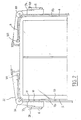
- the handling device according to the invention is intended to be mounted on a transport vehicle 2 and in particular on at least one of the side walls 4 and 5 and / or on the roof of said vehicle.
- the apparatus consists of two symmetrical and identical assemblies each allowing the lifting or lowering of loads 6 on either side of the vehicle 2.
- the loads can be constituted by heavy and bulky objects such as for example ladders, sections or tubes.
- Each assembly of the handling device comprises a mobile support member constituted by a front carriage 7a and a rear carriage 7b supporting for example a ladder 6.
- These two carriages 7a and 7b are identical and each of them is mounted movably on a rail 9a respectively 9b of a preferably rectangular section.
- the two rails 9a, 9b therefore form a guide frame for the carriages 7a and 7b.
- Each rail 9a, 9b follows the shape of the vehicle 2 and generally comprises a part in lower extending vertically on the side wall of the vehicle and an upper curved portion on the roof of said vehicle.
- the rails 9a, 9b are fixed to the vehicle 2 by means of spacers 10 in such a way that said rails extend at a certain distance from the side walls and from the roof of said vehicle.
- each assembly of the device can be connected to the roof together by intermediate elements, not shown, so as to form a single piece, which facilitates installation on the vehicle.
- the vertical parts of the rails 9a, 9b can be separated from the curved parts and pivotally mounted on the wall of the vehicle so as to retract if they encounter an obstacle.
- FIGS 3 and 4 show on a larger scale for example the carriage 7a forming a mobile support for the load.
- the carriage 7a comprises a chassis 11 constituted by a rectangular core 12 and by two lateral rectangular wings 13, 14 extending perpendicular to the core 12 so that the cross section of the chassis is U-shaped.
- the chassis 11 can also be made in one piece.
- the chassis 11 is provided with two horizontal parallel axles 15 and 16 respectively housed in openings 17 and 18 respectively formed in the two wings 13, 14 on the side opposite to the rectangular core 12.
- a guide flange 19 is mounted on each side so that one of the faces of each flange 19 is in abutment against the wing 13 or 14 the other side either in guide contact with the transverse face of the rail 9.
- the first pair of rollers 20 is threaded on the axle 15 in the immediate vicinity of the flanges 19 and rolls on the corresponding longitudinal face of the rail 9.
- the second pair of rollers 21 is arranged on the other side of the rail 9 and each roller is rotatably mounted on an axis 22 extending parallel to the axle 15 and fixed to one end of an arm 23, the l the other end is articulated on the projecting end of said axle 15. It is the same for axle 16.
- a removable carrier element in the form of a ladder holder 24 is associated with each carriage.
- the ladder holder comprises a rectangular plate 25 by which it is fixed to the chassis of the carriage by means of two hooks 26 disposed at the front end of the plate and which hang on the front edge of the core 12 of the chassis.
- the ladder holder is immobilized on the chassis using a fixing member in the form of a bolt 27.
- the ladder holder 24 is provided at its upper part with an L-shaped iron 28, the free end of which is directed upwards, the assembly being rigidified by at least one square 29 fixed to the plate 25.
- the ladder holder 24 has at its lower part at least one strap 30 for holding the ladder during movement of the vehicle.
- the ladder racks are removable and can easily be replaced by any other member such as, for example, tube holders, profile holders, etc. which can be fixed to the carriages in the same way.
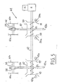
- Each carriage 7a, 7b is further provided with a pin 31 forming a member for fixing one end of a flexible link 32 ( Figures 1 and 2), preferably a cable, the other end of which is connected to a drive member designated as a whole by the reference 40 for raising or lowering the set of carriages.
- a flexible link 32 Figures 1 and 2
- Each cable 32 passes, at the level of the curvature between the side walls 4, 5 and the roof 2 of the vehicle, on a guide pulley 33, with horizontal axis and at the upper end of the rail on a return pulley 34 with axis vertical towards the drive member 40.
- This drive member 40 consists for each set of the device, two winding drums 41a, 41b on which the ends of the cables 32 are fixed.
- the drums 41a, 41b are wedged on a common drive shaft 42 which extends transversely above the roof 3 and which is carried by bearings, not shown, fixed on said roof.
- the shaft 42 of each assembly of the device is driven by a common electric motuer M via a gearbox 44 and a reduction gear R.
- the output shaft of the motor M drives via the reduction gear R an at least partially splined or grooved shaft 47.
- First and second pairs of bevel gears 48, 49, 50, 51 are mounted for rotation with the shaft 47, but axially free so that on the one hand the bevel wheels 48, 49 alternately engage with a conical toothed wheel 52 and, on the other hand, the conical wheels 50, 51 come alternately into engagement with a conical toothed wheel 53.
- the axes of the toothed wheels 52, 53 extend perpendicular to the axis 47.
- the bevel wheels 48, 49 and 50, 51 are kept apart with respect to each other by means of a spring respectively 54, 55 and the displacement of each bevel wheel 48, 49, 50 , 51 is controlled by a plunger electromagnet 48a, 49a, 50a, 51a respectively so as to rotate each toothed wheel 52 and 53 in one direction or the other as will be seen later.
- Each toothed wheel 52, 53 is connected to an endless screw 56, 57 which cooperates with a pinion respectively 58, 59 each mounted on the drive shaft 42 of the drums 41a, 41b.
- Each toothed wheel 52, 53 is further connected to a drive square 43a, 43b respectively, in order to allow manual drive of each set separately in the event of a power failure.
- the electromagnets 48a, 49a, 50a, 51a are electrically connected to a control panel arranged in the passenger compartment or in any other suitable location of the vehicle.
- Each set of the device is advantageously provided with limit switches, not shown, arranged at the start and at the end of the path of each carriage in order to limit the movement of the latter.
- the switches are electrically connected to the control panel which stops the motor as soon as the corresponding carriage comes into contact with a switch.
- the drive of the device can also be achieved by the PTO of the vehicle.
- the PTO is connected to the gearbox by a flexible connection.
- Each assembly of the apparatus is further provided with locking devices 101 (see FIG. 6) which hold the carriages 7a, 7b with their load 6 in their position on the roof 3 of the vehicle during transport.
- Each locking device comprises a disc 102 mounted idly on an axis 103 disposed transversely on each rail 9.
- the disc 102 extends towards the roof through a longitudinal slot 104 in the rail.
- the locking disc 102 is provided with a first notch 105 intended to cooperate with a transverse bar 106 disposed between the lateral wings 13, 14 of the carriage 7. This first notch 105 forms an angle of 90 °.
- a second rectangular locking notch 107 is disposed on the same semicircle as the first notch 104.
- the second notch 107 is intended to cooperate with a lock 108 guided in a slide 109 fixed to the bottom of the rail 9.
- the lock 108 is at its opposite end articulated on the end of a rod 110 of a jack 111 intended to move the lock 108 in its unlocked position.
- the rod 110 is connected to the end of a spring 112, the other end of which is hooked to a stud 113 fixed to the underside of the rail 9.
- the spring 112 biases the lock 108 towards the locking position of the latter. Ci in the notch 107 of the disc 102.
- the apparatus operates as follows. In what follows, we will limit our to describing the operation of one set of apparatus, the other set operating in a similar manner. It is obvious that the vehicle can be provided with only one assembly on one side or the other.
- the two carriages 7a, 7b of the entire apparatus are in their low position as shown in Figure 1, in contact with the respective limit switches.
- the ladder 6 is arranged transversely on the irons 28 of the two carriages 7a, 7b and attached using straps 30.
- the operator presses the corresponding button on the control panel so as to actuate the electromagnet for example 48a which moves the bevel wheel 48 against the action of the spring 54 towards its position in engagement with the bevel wheel 52.
- the motor M is started to drive the shaft 47 in rotation by means of the reduction gear A. The rotational movement is transmitted to the bevel wheel 52 by the bevel wheel 48.
- the bevel wheel 52 drives the drums 41a, 41b in the winding direction of each cable 32 by means of the worm screw 56, the pinion 58 and to the shaft 42.
- the carriages 7a and 7b guided by the rails 9a, 9b rise simultaneously with their load, pass through the curved part of these and continue towards the center of the roof until that they come into contact on the end switches race not shown.
- the electromagnet 48a is returned to its rest position and the bevel wheel 48, under the effect of the spring 54, moves away from the bevel wheel 52.
- each carriage 7a and 7b triggers the corresponding locking device 101.
- the transverse wheel 106 of each carriage enters the notch 105 of the disc 102 which has the effect of rotating said disc 90 ° so that the notch 107 comes to be positioned opposite the latch 108 which under the effect spring 112 penetrates into said notch to block the disc 102 and keep each carriage with its load in the high position during transport.
- the operator presses the corresponding button on the control panel so as to unlock the carriages 7a, 7b by recalling, via the jack 111, the lock 108 which emerges from the notch 107 in the disc 102 and then actuating the electromagnet, for example 49a, which moves the bevel wheel 49 against the action of the spring 54 towards its position in engagement with the toothed wheel 52.
- the motor M is started, this which drives in rotation, via the wheel 52, the worm screw 56, the pinion 58 and the shaft 42, the drums 41a, 41b in the direction of unwinding of the cables 32.
- the carriages 7a, 7b move downwards guided on the rails 9a, 9b until they come into contact with the limit switches.
- the electromagnet 49a then returns to its rest position and the bevel wheel 49 is biased by the spring 54 towards the position in which it is no longer engaged with the wheel 52.
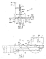
- the movable support member for receiving a load is formed by a receptacle 60 having the shape of an elongated tank and which is arranged in the center of the roof of the vehicle.
- the receptacle 60 can be moved longitudinally and is guided by a frame (62, 63) extending over the entire length of the receptacle 60.
- the frame consists of two vertical uprights 62 which provide a guide passage for the receptacle 60 and which comprise each at one of its ends a cutout 62a.
- a transverse axis 64 At the cutout 62a is positioned a transverse axis 64 on which are pivotally mounted two opposite vertical plates 63 which extend, at said cutout, the upper part of the vertical uprights 62.
- the vertical uprights 62 and the vertical plates 63 are provided , at regular intervals, horizontal support rollers 66 forming a raceway for the receptacle 60.
- the bottom of the receptacle 60 has on its outer surface tubular elements 65 extending over the entire length of said receptacle and which rest on the supporting rollers 66.
- the vertical plates 63 are further provided on their inner face with regularly spaced horizontal guide rollers 68 which are intended to penetrate into grooves 70 formed over the entire length of the lateral faces of the receptacle 60.
- a bracket 61 is provided at the end of the vertical uprights 62, opposite the cutout 62a, for vertically immobilize the receptacle 60 in the transport position.
- each vertical plate 63 is provided with a small tab 72 extending upwards and the free end of which is articulated at the end of a rod 74 of a damping cylinder 75.
- the other end of each cylinder 75 is articulated on the corresponding vertical upright 62.
- the bottom of the tank 60 is provided externally with a longitudinal rack 76 which cooperates with a toothed wheel 77 secured to a sleeve 78 mounted to rotate freely on the articulation axis 64. On the sleeve 78 is also fixed a pinion 79 .
- the pinion 79 is engaged with an endless screw forming a threaded part of a shaft 80a connected to a gearbox 80 by means of cardans 80b.
- the shaft 80a extends parallel to the roof of the vehicle and is at its ends carried by supports 81 connected to the roof.
- the shaft 80a is at its opposite end with respect to its threaded part connected to a bevel gear 82 (see FIG. 9).
- the bevel wheel 82 is arranged so as to be able to cooperate with one or the other of two bevel wheels 83, 84 mounted for rotation on a grooved or grooved drive shaft 85.
- the two wheels 83, 84 are axially displaceable to engage alternately with the wheel 82.
- each wheel 83, 84 The movement of each wheel 83, 84 to its position in engagement with the wheel 82 is controlled by an electromagnet 83a, 84a respectively.
- the bevel wheels 83, 84 are biased towards their released position by means of a spring 88, respectively 89 threaded on the drive shaft 85 and bearing on one side against the bevel wheel cor corresponding and on the other side against a support flange 90, respectively 91 mounted on the shaft 85.
- the shaft 85 is driven by an electric motor M via a reduction gear R.
- the drive of the The device can also, as in the first embodiment, be produced by the PTO of the vehicle and in this case there is a flexible connection between the PTO and the worm 93.
- the receptacle 60 is further provided with a limit switch, not shown, which is arranged at the front end of the receptacle in the grooves 70 and which is on one side actuated by the bracket 61 and the other side by one of the rollers 68.
- the device is, as in the first embodiment, provided with a control panel (not shown) arranged in the passenger compartment of the vehicle or in another easily accessible location.
- the apparatus according to the second embodiment which has just been described operates in the following manner.
- the receptacle 60 For transport, the receptacle 60 is in the position shown in Figures 7 and 8. To move the container backwards, the operator presses the corresponding button on the control panel, which activates the electromagnet for example 83a, in order to move the corresponding bevel wheel 83 in its position engaged with the bevel wheel 82 which drives the worm 80a in a first direction.
- the worm 80a drives the pinion 79 which is connected in rotation to the wheel 77 in engagement with the rack 76.
- the rack 76 moves longitudinally with the receptacle towards the rear of the vehicle.
- the receptacle guided by the rollers 66 and 68 is no longer blocked perpendicularly by the bracket 61 and cont bare its translational movement parallel to the roof of the vehicle, to a tilting position which is the position in which the center of gravity of the receptacle with its load is aligned with the axis of articulation 64.
- a tilting position which is the position in which the center of gravity of the receptacle with its load is aligned with the axis of articulation 64.
- the receptacle connected to the plates 63 by means of the rollers 68 rocks around the axis of articulation 64 with the plates.
- the tilting of this assembly is damped by the jacks 75, the rods 74 of which slowly come out of the cylinders. The tilting movement continues until the receptacle is inclined approximately 45 ° from the horizontal.
- the receptacle continues its translation until the end switch, not shown, comes into contact with the corresponding guide roller 68.
- the electromagnet 83a is no longer supplied and the bevel wheel 83 is released from the bevel gear 82 under the action of spring 88.
- the receptacle is now inclined at the rear of the vehicle and lowered to a height of approximately 30-40 cm from the ground, which allows a load to be removed or introduced.
- the operator acts on the control panel to control the motor and actuate the electromagnet 84a which moves the other bevel gear 84 to its position in engagement with the bevel gear 82.
- the pinion 77 acts on the rack 76 which has the effect of raising the receptacle on the roof of the vehicle.
- the receptacle is gradually moved to its tilting position towards the horizontal and it then continues its translation until the limit switch comes into contact with the bracket 61.
- the electromagnet is no longer powered and the bevel gear 84 disengages from the bevel gear 82 under the effect of the spring 89.
- the receptacle is again in its transport position.
- the toothed wheel 82 is also connected to a drive square 82a in order to allow manual drive in the event of an electrical failure.
Landscapes
- Engineering & Computer Science (AREA)
- Mechanical Engineering (AREA)
- Fittings On The Vehicle Exterior For Carrying Loads, And Devices For Holding Or Mounting Articles (AREA)
Applications Claiming Priority (1)
| Application Number | Priority Date | Filing Date | Title |
|---|---|---|---|
| FR8714525A FR2622160B1 (fr) | 1987-10-21 | 1987-10-21 | Appareil de manutention automatique de charges allongees sur le toit d'un vehicule |
Publications (1)
| Publication Number | Publication Date |
|---|---|
| EP0393286A1 true EP0393286A1 (de) | 1990-10-24 |
Family
ID=9356022
Family Applications (1)
| Application Number | Title | Priority Date | Filing Date |
|---|---|---|---|
| EP89401081A Withdrawn EP0393286A1 (de) | 1987-10-21 | 1989-04-19 | Automatische Be- und Entladungsvorrichtung für lange Ladungen auf einem Fahrzeugdach |
Country Status (3)
| Country | Link |
|---|---|
| EP (1) | EP0393286A1 (de) |
| FR (1) | FR2622160B1 (de) |
| WO (1) | WO1990012707A1 (de) |
Cited By (1)
| Publication number | Priority date | Publication date | Assignee | Title |
|---|---|---|---|---|
| DE29811774U1 (de) * | 1998-07-02 | 1998-08-20 | Frhr Von Der Goltz Peter Micha | Gepäck- und Sportgerätebeförderungsvorrichtung für Wohnmobil-Kraftfahrzeuge |
Families Citing this family (7)
| Publication number | Priority date | Publication date | Assignee | Title |
|---|---|---|---|---|
| FR2622160B1 (fr) * | 1987-10-21 | 1992-04-03 | Pobanz Gerard | Appareil de manutention automatique de charges allongees sur le toit d'un vehicule |
| US5104280A (en) * | 1991-01-18 | 1992-04-14 | Michael P. Ziaylek | Apparatus for use with an emergency vehicle for storage and retrieval of remotely located emergency devices |
| US5172952A (en) * | 1992-06-05 | 1992-12-22 | Ron Lasnetski | Overhead storage rack for storing ladders or the like |
| US5791857A (en) * | 1996-10-24 | 1998-08-11 | Theodore Ziaylek, Jr. | Automatic ladder lowering and storage device for use with an emergency vehicle |
| BE1014601A3 (nl) * | 2002-02-01 | 2004-01-13 | Garage Carl Verbauwhede Bvba | Inrichting voor het laden en/of lossen van een lading op/vanaf een voertuig. |
| US20040047716A1 (en) | 2002-09-05 | 2004-03-11 | L&P Property Management Company | Ladder rack apparatus and method |
| US7992682B2 (en) | 2007-12-21 | 2011-08-09 | Michael Paul Ziaylek | Ladder storing apparatus for use with an emergency vehicle |
Citations (8)
| Publication number | Priority date | Publication date | Assignee | Title |
|---|---|---|---|---|
| NL266008A (de) * | 1900-01-01 | |||
| FR986618A (fr) * | 1943-11-25 | 1951-08-02 | Voiture automobile pour le transport routier des voyageurs, comportant un appareil mécanique pour la manutention des bagages | |
| US2746628A (en) * | 1953-10-23 | 1956-05-22 | Charles S Neyra | Ladder support |
| FR2399366A1 (fr) * | 1977-08-03 | 1979-03-02 | Losserand Madoux Guy | Dispositif de stockage, de transport et de manutention d'objets |
| DE2931882A1 (de) * | 1979-08-06 | 1981-03-26 | Ronic Staal B.V., Woerden | Dachstaender fuer kraftfahrzeuge |
| US4439086A (en) * | 1982-07-01 | 1984-03-27 | Thede Ralph W | Boat loader |
| FR2600954A1 (fr) * | 1986-07-07 | 1988-01-08 | Sibille & Cie Ateliers | Appareil de manutention de charges allongees, telles que des echelles sur le toit d'un vehicule |
| FR2622160A1 (fr) * | 1987-10-21 | 1989-04-28 | Pobanz Gerard | Appareil de manutention automatique de charges allongees sur le toit d'un vehicule |
-
1987
- 1987-10-21 FR FR8714525A patent/FR2622160B1/fr not_active Expired - Lifetime
-
1989
- 1989-04-19 WO PCT/FR1989/000180 patent/WO1990012707A1/fr unknown
- 1989-04-19 EP EP89401081A patent/EP0393286A1/de not_active Withdrawn
Patent Citations (8)
| Publication number | Priority date | Publication date | Assignee | Title |
|---|---|---|---|---|
| NL266008A (de) * | 1900-01-01 | |||
| FR986618A (fr) * | 1943-11-25 | 1951-08-02 | Voiture automobile pour le transport routier des voyageurs, comportant un appareil mécanique pour la manutention des bagages | |
| US2746628A (en) * | 1953-10-23 | 1956-05-22 | Charles S Neyra | Ladder support |
| FR2399366A1 (fr) * | 1977-08-03 | 1979-03-02 | Losserand Madoux Guy | Dispositif de stockage, de transport et de manutention d'objets |
| DE2931882A1 (de) * | 1979-08-06 | 1981-03-26 | Ronic Staal B.V., Woerden | Dachstaender fuer kraftfahrzeuge |
| US4439086A (en) * | 1982-07-01 | 1984-03-27 | Thede Ralph W | Boat loader |
| FR2600954A1 (fr) * | 1986-07-07 | 1988-01-08 | Sibille & Cie Ateliers | Appareil de manutention de charges allongees, telles que des echelles sur le toit d'un vehicule |
| FR2622160A1 (fr) * | 1987-10-21 | 1989-04-28 | Pobanz Gerard | Appareil de manutention automatique de charges allongees sur le toit d'un vehicule |
Cited By (1)
| Publication number | Priority date | Publication date | Assignee | Title |
|---|---|---|---|---|
| DE29811774U1 (de) * | 1998-07-02 | 1998-08-20 | Frhr Von Der Goltz Peter Micha | Gepäck- und Sportgerätebeförderungsvorrichtung für Wohnmobil-Kraftfahrzeuge |
Also Published As
| Publication number | Publication date |
|---|---|
| FR2622160A1 (fr) | 1989-04-28 |
| FR2622160B1 (fr) | 1992-04-03 |
| WO1990012707A1 (fr) | 1990-11-01 |
Similar Documents
| Publication | Publication Date | Title |
|---|---|---|
| EP0918660B1 (de) | Tragende runge mit integrierter hubeinrichtung und tragender aufbau bestehend aus mindestens einem paar funktionell unter sich verbundener rungen | |
| EP0135452B1 (de) | Hubeinrichtung mit wenigstens einem Teleskopmast | |
| EP0567475B1 (de) | Automatische mechanische anlage zum abstellen von objekten, insbesondere von kraftfahrzeugen | |
| FR2480631A1 (fr) | Procede de tri ou de transport et installation et chariot pour sa mise en oeuvre | |
| EP0307331B1 (de) | Einrichtung zum Wiederherstellen und Kontrollieren von beschädigten Fahrzeugkarosserien | |
| CA2043243C (fr) | Tablier escamotable pour couvrir de facon continuelle le puits d'un verin a empattement variable | |
| FR2984292A1 (fr) | Dispositif elevateur de personnes et ou de charges | |
| FR2581004A1 (fr) | Dispositif de manoeuvre de conteneur | |
| EP0393286A1 (de) | Automatische Be- und Entladungsvorrichtung für lange Ladungen auf einem Fahrzeugdach | |
| FR2623891A1 (fr) | Installation pour briqueter la paroi interieure d'une enceinte | |
| FR2727075A1 (fr) | Dispositif roulant de banderolage helicoidal non automoteur a support de bobine mobile verticalement | |
| FR2644196A1 (fr) | Procede et dispositif de prise en charge d'un vehicule pour installation de parcage automobile | |
| FR2640944A1 (de) | ||
| FR2684341A1 (fr) | Dispositif pour hisser ou retirer une echelle ou analogue sur ou a partir d'une galerie de toit d'un vehicule. | |
| EP0114143B1 (de) | Selbsttätiger Lastenaufzug | |
| EP0694001B1 (de) | Auf einem wagendach schwenkbare hebevorrichtung für einen rollstuhl | |
| FR2574773A1 (fr) | Chariot de reception et de transport d'une piece de tricot pour metiers circulaires | |
| WO2018115607A1 (fr) | Grue de levage comprenant un dispositif de levage à double mouflage | |
| FR2528815A1 (fr) | Appareil du genre destine a etre accole a une construction pour le transfert de charges selon des directions verticale et transversale | |
| FR2752233A1 (fr) | Dispositif de manutention, a montage en kit, pour vehicules utilitaires et similaires | |
| FR2464351A1 (fr) | Dispositif pour amener des charges, notamment metriaux de construction, d'un emplacement determine a un autre emplacement espaces en hauteur et lateralement | |
| EP0062342A1 (de) | Einrichtung zum schnellen Beladen von Förderwagen, insbesondere von Lastkraftwagen | |
| WO2008155471A1 (fr) | Equipement rapportable sur le chassis d'un vehicule utilitaire pour la manutention d'un element portant une charge | |
| FR2623485A1 (fr) | Appareil de manutention destine a hisser des charges telles que par exemple des echelles sur le toit d'un vehicule | |
| FR2530201A1 (fr) | Appareil de chargement automatique du volume total d'un vehicule de transport |
Legal Events
| Date | Code | Title | Description |
|---|---|---|---|
| PUAI | Public reference made under article 153(3) epc to a published international application that has entered the european phase |
Free format text: ORIGINAL CODE: 0009012 |
|
| AK | Designated contracting states |
Kind code of ref document: A1 Designated state(s): AT BE CH DE ES FR GB GR IT LI LU NL SE |
|
| STAA | Information on the status of an ep patent application or granted ep patent |
Free format text: STATUS: THE APPLICATION IS DEEMED TO BE WITHDRAWN |
|
| 18D | Application deemed to be withdrawn |
Effective date: 19910425 |