EP0392978A1 - Micropompe à débit constant - Google Patents
Micropompe à débit constant Download PDFInfo
- Publication number
- EP0392978A1 EP0392978A1 EP90810272A EP90810272A EP0392978A1 EP 0392978 A1 EP0392978 A1 EP 0392978A1 EP 90810272 A EP90810272 A EP 90810272A EP 90810272 A EP90810272 A EP 90810272A EP 0392978 A1 EP0392978 A1 EP 0392978A1
- Authority
- EP
- European Patent Office
- Prior art keywords
- pumping chamber
- micropump
- wall
- deformable wall
- stop
- Prior art date
- Legal status (The legal status is an assumption and is not a legal conclusion. Google has not performed a legal analysis and makes no representation as to the accuracy of the status listed.)
- Withdrawn
Links
- 238000005086 pumping Methods 0.000 claims abstract description 73
- XUIMIQQOPSSXEZ-UHFFFAOYSA-N Silicon Chemical compound [Si] XUIMIQQOPSSXEZ-UHFFFAOYSA-N 0.000 claims abstract description 20
- 239000011521 glass Substances 0.000 claims abstract description 20
- 229910052710 silicon Inorganic materials 0.000 claims abstract description 20
- 239000010703 silicon Substances 0.000 claims abstract description 20
- 238000005530 etching Methods 0.000 claims abstract description 14
- 238000006073 displacement reaction Methods 0.000 claims abstract description 6
- 239000012530 fluid Substances 0.000 claims description 9
- 238000004891 communication Methods 0.000 claims description 3
- 229910021421 monocrystalline silicon Inorganic materials 0.000 claims description 3
- 239000008188 pellet Substances 0.000 abstract description 8
- 235000012431 wafers Nutrition 0.000 description 33
- VYPSYNLAJGMNEJ-UHFFFAOYSA-N Silicium dioxide Chemical compound O=[Si]=O VYPSYNLAJGMNEJ-UHFFFAOYSA-N 0.000 description 8
- 239000012528 membrane Substances 0.000 description 6
- 229910052681 coesite Inorganic materials 0.000 description 4
- 229910052906 cristobalite Inorganic materials 0.000 description 4
- 239000000377 silicon dioxide Substances 0.000 description 4
- 235000012239 silicon dioxide Nutrition 0.000 description 4
- 229910052682 stishovite Inorganic materials 0.000 description 4
- 229910052905 tridymite Inorganic materials 0.000 description 4
- 239000003814 drug Substances 0.000 description 3
- 229940079593 drug Drugs 0.000 description 3
- 239000000463 material Substances 0.000 description 3
- 238000000034 method Methods 0.000 description 3
- 238000003466 welding Methods 0.000 description 3
- 230000032683 aging Effects 0.000 description 2
- 238000010586 diagram Methods 0.000 description 2
- 238000010292 electrical insulation Methods 0.000 description 2
- 239000007788 liquid Substances 0.000 description 2
- 238000000206 photolithography Methods 0.000 description 2
- 239000004830 Super Glue Substances 0.000 description 1
- 238000004026 adhesive bonding Methods 0.000 description 1
- 230000007423 decrease Effects 0.000 description 1
- 230000003247 decreasing effect Effects 0.000 description 1
- 230000001419 dependent effect Effects 0.000 description 1
- FGBJXOREULPLGL-UHFFFAOYSA-N ethyl cyanoacrylate Chemical compound CCOC(=O)C(=C)C#N FGBJXOREULPLGL-UHFFFAOYSA-N 0.000 description 1
- 238000002513 implantation Methods 0.000 description 1
- 238000011065 in-situ storage Methods 0.000 description 1
- 230000001939 inductive effect Effects 0.000 description 1
- 238000012886 linear function Methods 0.000 description 1
- 238000003754 machining Methods 0.000 description 1
- 238000004519 manufacturing process Methods 0.000 description 1
- 238000005459 micromachining Methods 0.000 description 1
- 230000003071 parasitic effect Effects 0.000 description 1
Images

Classifications
-
- F—MECHANICAL ENGINEERING; LIGHTING; HEATING; WEAPONS; BLASTING
- F04—POSITIVE - DISPLACEMENT MACHINES FOR LIQUIDS; PUMPS FOR LIQUIDS OR ELASTIC FLUIDS
- F04B—POSITIVE-DISPLACEMENT MACHINES FOR LIQUIDS; PUMPS
- F04B43/00—Machines, pumps, or pumping installations having flexible working members
- F04B43/02—Machines, pumps, or pumping installations having flexible working members having plate-like flexible members, e.g. diaphragms
- F04B43/04—Pumps having electric drive
- F04B43/043—Micropumps
- F04B43/046—Micropumps with piezoelectric drive
-
- A—HUMAN NECESSITIES
- A61—MEDICAL OR VETERINARY SCIENCE; HYGIENE
- A61M—DEVICES FOR INTRODUCING MEDIA INTO, OR ONTO, THE BODY; DEVICES FOR TRANSDUCING BODY MEDIA OR FOR TAKING MEDIA FROM THE BODY; DEVICES FOR PRODUCING OR ENDING SLEEP OR STUPOR
- A61M2205/00—General characteristics of the apparatus
- A61M2205/02—General characteristics of the apparatus characterised by a particular materials
- A61M2205/0244—Micromachined materials, e.g. made from silicon wafers, microelectromechanical systems [MEMS] or comprising nanotechnology
-
- A—HUMAN NECESSITIES
- A61—MEDICAL OR VETERINARY SCIENCE; HYGIENE
- A61M—DEVICES FOR INTRODUCING MEDIA INTO, OR ONTO, THE BODY; DEVICES FOR TRANSDUCING BODY MEDIA OR FOR TAKING MEDIA FROM THE BODY; DEVICES FOR PRODUCING OR ENDING SLEEP OR STUPOR
- A61M2205/00—General characteristics of the apparatus
- A61M2205/02—General characteristics of the apparatus characterised by a particular materials
- A61M2205/0272—Electro-active or magneto-active materials
- A61M2205/0294—Piezoelectric materials
Definitions
- the present invention relates to a micropump of the type in which at least part of the pump mechanism is produced by machining a silicon wafer using photolithography techniques.
- Micropumps can be used in particular for the in situ administration of drugs, the miniaturization of the pump possibly allowing a permanent implantation thereof in the body. These pumps allow precise dosing of small quantities of fluid to be injected.
- micropumps are described in particular in the article "A piezoelectric micropump based on micromachining of silicon” by H. van Lintel et al. published in Sensors and Actuators, no 15, 1988, pp 153-157. These micropumps essentially comprise a stack of three wafers, that is to say a silicon wafer disposed between two glass wafers.
- the silicon wafer is etched to form a cavity, which with one of the glass wafers defines the pumping chamber, at least one suction valve and at least one discharge valve putting the pumping chamber in communication respectively with a input channel and an output channel.
- the part of the glass plate forming a wall of the pumping chamber can be deformed by a control element constituted for example by a piezoelectric pellet. This is equipped with two electrodes which, when connected to a source of electric voltage, cause the deformation of the pellet and, consequently, the deformation of the glass plate, which causes a variation in the volume of the pumping chamber.
- the deformable wall of the pumping chamber can thus be moved between a first position, in which it is relatively distant from the opposite wall, when the piezoelectric pad is not subjected to any electrical voltage, and a second position, in which it is closer to the opposite wall, when a voltage is applied between the electrodes of the piezoelectric pad.
- the operation of the micropump is as follows. When no electrical voltage is applied to the piezoelectric pad, the suction and discharge valves are in the closed position. When an electrical voltage is applied, there is an increase in pressure in the pumping chamber which causes the opening of the discharge valve as soon as the pressure in the chamber is greater than the sum of the pressure in the outlet channel and of the pressure created by the pre-tensioning of the valve. The fluid contained in the pumping chamber is then discharged towards the outlet channel by the displacement of the deformable wall from the first position to the second position. During this phase, the suction valve is kept closed by the pressure prevailing in the pumping chamber.
- micropumps are used in particular for the administration of drugs. It is therefore important that the flow rate of the micropump is well determined, so that the drug to be injected is dosed very precisely.
- the known micropumps have certain imperfections on this point.
- the flow rate of the micropump depends on the variation in volume of the pumping chamber between the two positions of the deformable wall. This variation in volume depends on several parameters, including the electrical voltage applied to the piezoelectric pellet and the physical characteristics of the piezoelectric pellet (thickness, diameter, dielectric constant) and of the deformable wall (material, thickness). So the same tension applied to apparently identical micropumps can cause different deformations of the pumping chambers of these micropumps which, consequently, will have different flow rates.
- the flow rate can change over time due to the aging of the materials.
- the flow rate of the micropump depends on the pressure in the outlet channel, since the discharge valve opens only when the pressure in the pumping chamber is greater than the sum of the pressure in the outlet channel and the pressure created by the pre-tensioning of the valve.
- the object of the invention is to solve in particular the drawbacks mentioned, in order to achieve a substantially constant flow rate of the micropump, and in particular independent of the manufacturing tolerances of the micropump, the aging thereof and the pressure in the channel. Release.
- the micropump conventionally comprises a plurality of plates attached to one another in a sealed manner in which a pumping chamber is formed, defined by two adjacent plates delimiting a cavity obtained by etching at least one of these plates, at least one suction valve and at least one discharge valve putting the pumping chamber in communication respectively with an inlet channel and an outlet channel, this micropump further comprising a control element for elastically deforming the part of a plate constituting a wall of the pumping chamber between a first position, where this deformed wall is further from the opposite wall of the pumping chamber and a second position, where this wall is relatively close to this opposite wall, displacements of the deformable wall causing the suction or the delivery of a fluid.
- this micropump is characterized in that the pumping chamber has a stop which determines the second position of the deformable wall.
- This stop limits the movement of the deformable wall towards the opposite wall of the pumping chamber. This makes it possible to very precisely define the volume of the pumping chamber at the end of the fluid delivery operation.
- the stop makes it possible to have a flow rate substantially independent of the pressure prevailing in the outlet channel since it is possible to impose on the piezoelectric pellet a high voltage, inducing a high pressure in the pumping chamber, therefore greater than the sum of the pressure prevailing in the outlet channel under normal conditions of use and the pressure created by the pre-tension of the discharge valve, without this resulting in an increase in the amplitude of the movement of the wall deformable, which remains fixed by the stop.
- This stop can be produced in particular in the form of one or more bosses, which can be formed in the bottom of the cavity during the etching of the wafer in which this cavity is produced, and / or produced by etching, gluing or other on the deformable wall.
- the stop can also be constituted simply by the very bottom of this cavity as soon as the height of the pumping chamber is chosen equal to the desired amplitude of the movement of the deformable wall.
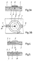
- FIG. 1A A first embodiment of a pumping chamber for a micropump according to the invention will be described with reference to Figures 1A, 1B, 1C.
- This pumping chamber is delimited by plates 2, 4 joined to one another in a sealed manner, for example by anodic welding or by bonding. These plates generally have a thickness of the order of a few tenths of a millimeter.
- the cavity 6 defining the pumping chamber, as well as an inlet channel 8 and an outlet channel 10, are obtained by etching the wafer 2 using well-known photolithography techniques, such as phase etching. liquid.
- the cavity has a diameter of around 1 cm and a height of between 5 and 200 micrometers.
- the wafer 2 is made of a material which can be easily etched, such as monocrystalline silicon; the plate 4 is for example made of glass.
- a control element such as, for example, a piezoelectric patch 12 is bonded to the outer face of the wafer 4, at the level of the cavity 6. This piezoelectric patch is covered on each of its faces with an electrode connected to a source voltage (not shown).
- FIGS. 1A and 2 respectively illustrate the position of the plate 4 according to whether no electrical voltage is applied to the piezoelectric pad 12 (first position) or that an electrical voltage is applied to this piezoelectric pad (second position).
- the pumping chamber is provided with a stop 14 which, by limiting the amplitude of movement of the deformable wall 13 of the plate 4) perfectly determines the second position of this deformable wall. It follows that the volume of the pumping chamber, at the end of the discharge operation, that is to say when the deformable wall 13 is in the second position, has a perfectly defined and reproducible value.
- the distance between the stop and the opposite wall of the chamber, when the deformable wall is in the first position, is of the order of 10 ⁇ m or less. This distance obviously depends on the dimensions of the pumping chamber and the desired fluid flow.
- the piezoelectric pad 12 is fixed on the glass plate 4. It is of course possible to fix the piezoelectric pad 12 on the silicon wafer 2.
- Such a chamber pumping was shown in section along line III-III and in bottom view respectively in Figures 3A and 3B.
- the stop 14 is constituted by a boss which extends from a wall of the pumping chamber. This boss is produced in the silicon wafer 2, during the etching of the cavity and the inlet and outlet channels.
- the upper surface 18 of the boss, against which the opposite wall of the pumping chamber abuts when the piezoelectric pellet is subjected to an electric voltage, is preferably planar. This allows the second position of the deformable wall to be defined more precisely.
- FIGS. 3A and 3B show cross sections of such a pumping chamber respectively in the first position and in the second position of the deformable plate 4.
- the pumping chamber is defined by a cavity 6 connected to a channel inlet 8 and an outlet channel (not shown).
- This pumping chamber is composed of a silicon wafer 2 and a glass wafer 4 as in the previous figures.
- the piezoelectric chip is placed on the glass plate 4; it is understood that this chip 12 can also be placed on the silicon wafer 2, as in FIGS. 3A and 3B.
- the use of the bottom 20 of the cavity 6 as a stop for the deformable wall has the advantage of reducing the number of operations necessary to etch the silicon wafer 2, compared to the previous embodiments in which the stop is constituted by a boss.
- the volume of the chamber at the end of the discharge phase is very low. This ensures efficient pumping even if the liquid contains a lot of gas bubbles (provided that the parasitic volume between the valves and the chamber itself is also very low).
- the volume of the pumping chamber remains large enough at the end of the delivery phase, and this is generally the case when the stop is a boss, the gas bubbles can be compressed without being expelled from the pumping chamber.
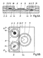
- FIG. 6A and 6B An embodiment of such a micropump according to the invention is shown in section along line VI-VI and in bottom view respectively in Figures 6A and 6B.
- This micropump mainly comprises a silicon wafer 22 disposed between glass wafers 24 and 26.
- the wafer 22 is etched on one side to form a cavity 28, defining the pumping chamber, and on the other side to adjust the thickness of the part of the plate 22 which constitutes the deformable wall 30 of the pumping chamber. This thickness is for example 150 ⁇ m.
- the two faces of the plate 22 are further etched to form a membrane 32 and an annular rib 34 of a suction valve, a membrane 36 and an annular rib 38 of a discharge valve, and an inlet channel 40a, 40b and an outlet channel 42a, 42b.
- these are covered with a thin layer 35, 39 of SiO2.
- the piezoelectric pad 44 making it possible to control the movement of the deformable wall 30 is bonded using a cyano-acrylate adhesive after the deformable wall has been covered with a thin layer 46 of SiO2, to ensure electrical insulation.
- the piezoelectric chip 44 can be of the PXE-5 type from Philips, having a diameter of 10 mm and a thickness of 0.20 mm.
- This plate can have a diameter of 5 cm and a thickness of the order of 300 micrometers.
- the plates 24 and 26 are made of polished glass. They have a diameter of 5 cm and a thickness of 1 mm.
- the plate 24 is pierced with an inlet hole 48 and an outlet hole 50.
- the plates 24 and 26 are tightly joined to the wafer 22 by means of the technique known under the name of anode welding.
- the height of the pumping chamber that is to say the distance between the deformable wall 30 and the plate 26 when no electrical voltage is applied to the pellet piezoelectric 44, is chosen (during the etching of the wafer 22) so that the stop is formed by the surface of the wafer 26.
- the pumping chamber is therefore similar to that described with reference to Figures 4 and 5, the only difference being that the piezoelectric chip is fixed on the silicon wafer instead of being on the glass wafer.
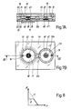
- FIGS. 7A and 7B show respectively a section along line VII-VII and a top view of a micropump according to another embodiment of the invention.
- This micropump has a greater compactness than the micropump shown in FIGS. 6A and 6B. This is achieved by placing the suction valve of the micropump directly on one of the walls of the pumping chamber. It would also be possible to place part of the discharge valve there.
- This micropump consists of a sicilicum plate 52 disposed between two glass plates 54 and 56.
- One face of the plate 52 is etched to form a cavity 58, defining the pumping chamber and during this etching operation, a boss 60 is formed to constitute a stop according to the invention.
- the two faces of the silicon wafer 52 are also etched to form a membrane 62 and an annular rib 64 of a suction valve, a membrane 66 and an annular rib 68 of a discharge valve, and a channel inlet 70 and an outlet channel 72a, 72b.
- Layers 65, 67 of SiO2 are formed on the annular ribs 64, 68 to avoid adhesion of the valves on the glass plates.
- the suction valve is preferably centered on the cavity 58.
- the boss 60 also centered with respect to the cavity 58 and to the suction valve, is in the form of a ring.
- the valves can be fitted with an amplitude limiter to reduce the risk of the membrane breaking.
- this limiter is constituted by an annular rib 69; for the suction valve, it is the boss 60 which plays the role of limiter.
- Channels 71, 73 are preferably provided in the amplitude limiters of the valves, to allow the fluid to flow when these limiters are in contact with the glass plates 54, 56.
- the glass plates 54 and 56 are tightly fixed by anodic welding to the silicon wafer 52, the glass wafer 54 being provided with an inlet opening 74 and an outlet opening 76.
- the deformable wall 78 of the pumping chamber is formed by a part of the glass plate 56; its thickness is of the order of 200 ⁇ m.
- a piezoelectric pad 80 is bonded to this wall 78 to control the movement.
- the annular boss 60 limits the amplitude of the movement of the deformable wall, which makes it possible to precisely define the volume of the pumping chamber at the end of the delivery operation.
- the flow 0 ⁇ of a conventional micropump with two valves is a linear function of the pressure p prevailing at the outlet of the micropump (curve A).
- the 0 ⁇ flow rate of a micropump according to the invention is substantially constant, in the ranges of normal operating pressures (curve B). This results from the fact that, for a pressure lower than a maximum operating pressure, the variation in volume caused by the displacement of the deformable wall is limited. The flow rate is thus practically the same as that corresponding to the maximum operating pressure.
Applications Claiming Priority (2)
| Application Number | Priority Date | Filing Date | Title |
|---|---|---|---|
| CH1369/89A CH679555A5 (da) | 1989-04-11 | 1989-04-11 | |
| CH1369/89 | 1989-04-11 |
Publications (1)
| Publication Number | Publication Date |
|---|---|
| EP0392978A1 true EP0392978A1 (fr) | 1990-10-17 |
Family
ID=4208807
Family Applications (1)
| Application Number | Title | Priority Date | Filing Date |
|---|---|---|---|
| EP90810272A Withdrawn EP0392978A1 (fr) | 1989-04-11 | 1990-04-05 | Micropompe à débit constant |
Country Status (8)
| Country | Link |
|---|---|
| US (1) | US5085562A (da) |
| EP (1) | EP0392978A1 (da) |
| JP (1) | JPH03505771A (da) |
| AU (1) | AU628153B2 (da) |
| CA (1) | CA2014235A1 (da) |
| CH (1) | CH679555A5 (da) |
| PT (1) | PT93712A (da) |
| WO (1) | WO1990012209A1 (da) |
Cited By (11)
| Publication number | Priority date | Publication date | Assignee | Title |
|---|---|---|---|---|
| WO1991007591A1 (en) * | 1989-11-10 | 1991-05-30 | Westonbridge International Limited | Micropump with improved priming |
| WO1991013255A1 (de) * | 1990-02-27 | 1991-09-05 | Fraunhofer-Gesellschaft zur Förderung der angewandten Forschung e.V. | Mikrominiaturisierte pumpe |
| EP0465229A1 (en) * | 1990-07-02 | 1992-01-08 | Seiko Epson Corporation | Micropump and process for manufacturing a micropump |
| WO1993005295A1 (de) * | 1991-09-11 | 1993-03-18 | Fraunhofer-Gesellschaft zur Förderung der angewandten Forschung e.V. | Mikrominiaturisierte, elektrostatisch betriebene mikromembranpumpe |
| DE4138491A1 (de) * | 1991-11-23 | 1993-05-27 | Juergen Dipl Ing Joswig | Mikromechanisches ventil fuer mikromechanische dosiereinrichtungen |
| DE4223019C1 (de) * | 1992-07-13 | 1993-11-18 | Fraunhofer Ges Forschung | Ventillose Mikropumpe |
| DE4332720A1 (de) * | 1993-09-25 | 1995-03-30 | Kernforschungsz Karlsruhe | Mikromembranpumpe |
| WO1995018307A1 (fr) * | 1993-12-28 | 1995-07-06 | Westonbridge International Limited | Micropompe |
| WO1997010435A2 (de) * | 1995-09-15 | 1997-03-20 | Institut Für Mikro- Und Informationstechnik Hahn-Schickard-Gesellschaft | Rückschlagventillose fluidpumpe |
| WO1999009321A1 (fr) * | 1997-08-20 | 1999-02-25 | Westonbridge International Limited | Micropompe comprenant un organe de controle d'entree permettant son auto-amorcage |
| WO2011058140A3 (en) * | 2009-11-13 | 2011-12-01 | Commissariat à l'énergie atomique et aux énergies alternatives | Method for producing at least one deformable membrane micropump and deformable membrane micropump |
Families Citing this family (232)
| Publication number | Priority date | Publication date | Assignee | Title |
|---|---|---|---|---|
| CA2009991A1 (en) * | 1989-02-15 | 1990-08-15 | Witold Cieplak | Pertussis toxin gene: cloning and expression of protective antigen |
| US7232671B2 (en) * | 1989-02-15 | 2007-06-19 | The United States Of America As Represented By The Secretary, Department Of Health And Human Services | Pertussis toxin gene: cloning and expression of protective antigen |
| KR920701670A (ko) * | 1989-06-14 | 1992-08-12 | 원본미기재 | 개선된 마이크로펌프(micropump). |
| ES2075459T3 (es) * | 1990-08-31 | 1995-10-01 | Westonbridge Int Ltd | Valvula equipada con detector de posicion y microbomba que incorpora dicha valvula. |
| DE4035852A1 (de) * | 1990-11-10 | 1992-05-14 | Bosch Gmbh Robert | Mikroventil in mehrschichtenaufbau |
| DE69313766T2 (de) * | 1992-04-02 | 1998-02-26 | Seiko Epson Corp | Mikrosteuervorrichtung fuer fluidum und verfahren zu deren herstellung |
| US5433351A (en) * | 1992-05-01 | 1995-07-18 | Misuzuerie Co., Ltd. | Controlled liquid dispensing apparatus |
| DE4223067C2 (de) * | 1992-07-14 | 1997-08-07 | Univ Dresden Tech | Mikromechanischer Durchflußbegrenzer in Mehrschichtenstruktur |
| US5628719A (en) * | 1992-11-25 | 1997-05-13 | Scimed Life Systems, Inc. | In vivo mechanical energy source and perfusion pump |
| EP0733169B1 (en) * | 1993-10-04 | 2003-01-08 | Research International, Inc. | Micromachined fluid handling apparatus comprising a filter and a flow regulator |
| DE4402119C2 (de) * | 1994-01-25 | 1998-07-23 | Karlsruhe Forschzent | Verfahren zur Herstellung von Mikromembranpumpen |
| DE4405026A1 (de) * | 1994-02-17 | 1995-08-24 | Rossendorf Forschzent | Mikro-Fluidmanipulator |
| CA2190098C (en) * | 1994-05-13 | 2006-04-25 | Michael W. Lawless | Disposable fluid infusion pumping chamber cassette having a push button flow stop thereon |
| US5462256A (en) * | 1994-05-13 | 1995-10-31 | Abbott Laboratories | Push button flow stop useable with a disposable infusion pumping chamber cassette |
| US5769608A (en) * | 1994-06-10 | 1998-06-23 | P.D. Coop, Inc. | Resonant system to pump liquids, measure volume, and detect bubbles |
| WO1997005385A1 (fr) * | 1995-07-27 | 1997-02-13 | Seiko Epson Corporation | Microsoupape et son procede de realisation, micropompe utilisant cette microsoupape, et son procede de realisation, et dispositif utilisant cette micropompe |
| DE19534137A1 (de) * | 1995-09-14 | 1997-03-20 | Univ Ilmenau Tech | Mikro-Ventilanordnung |
| US5919582A (en) | 1995-10-18 | 1999-07-06 | Aer Energy Resources, Inc. | Diffusion controlled air vent and recirculation air manager for a metal-air battery |
| DE19546570C1 (de) * | 1995-12-13 | 1997-03-27 | Inst Mikro Und Informationstec | Fluidpumpe |
| US5997263A (en) * | 1996-02-09 | 1999-12-07 | Westonbridge International Limited | Micromachined filter for a micropump |
| EP0880817B1 (en) | 1996-02-10 | 2005-04-27 | Fraunhofer-Gesellschaft zur Förderung der angewandten Forschung e.V. | Bistable microactuator with coupled membranes |
| DE19637928C2 (de) * | 1996-02-10 | 1999-01-14 | Fraunhofer Ges Forschung | Bistabile Membran-Aktivierungseinrichtung und Membran |
| DE19648695C2 (de) | 1996-11-25 | 1999-07-22 | Abb Patent Gmbh | Vorrichtung zur automatischen und kontinuierlichen Analyse von Flüssigkeitsproben |
| FR2757906A1 (fr) * | 1996-12-31 | 1998-07-03 | Westonbridge Int Ltd | Micropompe avec piece intermediaire integree |
| DE19802367C1 (de) * | 1997-02-19 | 1999-09-23 | Hahn Schickard Ges | Mikrodosiervorrichtungsarray und Verfahren zum Betreiben desselben |
| JP3582316B2 (ja) * | 1997-08-20 | 2004-10-27 | 株式会社日立製作所 | 化学分析装置 |
| US7485263B2 (en) * | 1997-08-26 | 2009-02-03 | Eppendorf Ag | Microproportioning system |
| US6833242B2 (en) * | 1997-09-23 | 2004-12-21 | California Institute Of Technology | Methods for detecting and sorting polynucleotides based on size |
| US7214298B2 (en) * | 1997-09-23 | 2007-05-08 | California Institute Of Technology | Microfabricated cell sorter |
| JP3543604B2 (ja) * | 1998-03-04 | 2004-07-14 | 株式会社日立製作所 | 送液装置および自動分析装置 |
| US6247908B1 (en) * | 1998-03-05 | 2001-06-19 | Seiko Instruments Inc. | Micropump |
| US6780591B2 (en) * | 1998-05-01 | 2004-08-24 | Arizona Board Of Regents | Method of determining the nucleotide sequence of oligonucleotides and DNA molecules |
| US7875440B2 (en) | 1998-05-01 | 2011-01-25 | Arizona Board Of Regents | Method of determining the nucleotide sequence of oligonucleotides and DNA molecules |
| US6436564B1 (en) | 1998-12-18 | 2002-08-20 | Aer Energy Resources, Inc. | Air mover for a battery utilizing a variable volume enclosure |
| US6475658B1 (en) | 1998-12-18 | 2002-11-05 | Aer Energy Resources, Inc. | Air manager systems for batteries utilizing a diaphragm or bellows |
| US7244396B2 (en) * | 1999-04-06 | 2007-07-17 | Uab Research Foundation | Method for preparation of microarrays for screening of crystal growth conditions |
| US7247490B2 (en) | 1999-04-06 | 2007-07-24 | Uab Research Foundation | Method for screening crystallization conditions in solution crystal growth |
| US7214540B2 (en) * | 1999-04-06 | 2007-05-08 | Uab Research Foundation | Method for screening crystallization conditions in solution crystal growth |
| US7250305B2 (en) * | 2001-07-30 | 2007-07-31 | Uab Research Foundation | Use of dye to distinguish salt and protein crystals under microcrystallization conditions |
| US20030022383A1 (en) * | 1999-04-06 | 2003-01-30 | Uab Research Foundation | Method for screening crystallization conditions in solution crystal growth |
| US6210128B1 (en) * | 1999-04-16 | 2001-04-03 | The United States Of America As Represented By The Secretary Of The Navy | Fluidic drive for miniature acoustic fluidic pumps and mixers |
| US7501245B2 (en) * | 1999-06-28 | 2009-03-10 | Helicos Biosciences Corp. | Methods and apparatuses for analyzing polynucleotide sequences |
| US8052792B2 (en) * | 2001-04-06 | 2011-11-08 | California Institute Of Technology | Microfluidic protein crystallography techniques |
| KR100865105B1 (ko) | 1999-06-28 | 2008-10-24 | 캘리포니아 인스티튜트 오브 테크놀로지 | 마이크로 가공된 탄성중합체 밸브 및 펌프 시스템 |
| US7217321B2 (en) * | 2001-04-06 | 2007-05-15 | California Institute Of Technology | Microfluidic protein crystallography techniques |
| US7195670B2 (en) * | 2000-06-27 | 2007-03-27 | California Institute Of Technology | High throughput screening of crystallization of materials |
| US7244402B2 (en) * | 2001-04-06 | 2007-07-17 | California Institute Of Technology | Microfluidic protein crystallography |
| US8709153B2 (en) | 1999-06-28 | 2014-04-29 | California Institute Of Technology | Microfludic protein crystallography techniques |
| US20080277007A1 (en) * | 1999-06-28 | 2008-11-13 | California Institute Of Technology | Microfabricated elastomeric valve and pump systems |
| US8550119B2 (en) * | 1999-06-28 | 2013-10-08 | California Institute Of Technology | Microfabricated elastomeric valve and pump systems |
| US7144616B1 (en) | 1999-06-28 | 2006-12-05 | California Institute Of Technology | Microfabricated elastomeric valve and pump systems |
| US6929030B2 (en) * | 1999-06-28 | 2005-08-16 | California Institute Of Technology | Microfabricated elastomeric valve and pump systems |
| US6818395B1 (en) | 1999-06-28 | 2004-11-16 | California Institute Of Technology | Methods and apparatus for analyzing polynucleotide sequences |
| US6899137B2 (en) * | 1999-06-28 | 2005-05-31 | California Institute Of Technology | Microfabricated elastomeric valve and pump systems |
| US7306672B2 (en) * | 2001-04-06 | 2007-12-11 | California Institute Of Technology | Microfluidic free interface diffusion techniques |
| US7459022B2 (en) | 2001-04-06 | 2008-12-02 | California Institute Of Technology | Microfluidic protein crystallography |
| US7052545B2 (en) * | 2001-04-06 | 2006-05-30 | California Institute Of Technology | High throughput screening of crystallization of materials |
| WO2001067369A2 (en) * | 2000-03-03 | 2001-09-13 | California Institute Of Technology | Combinatorial array for nucleic acid analysis |
| US20050118073A1 (en) * | 2003-11-26 | 2005-06-02 | Fluidigm Corporation | Devices and methods for holding microfluidic devices |
| US7867763B2 (en) * | 2004-01-25 | 2011-01-11 | Fluidigm Corporation | Integrated chip carriers with thermocycler interfaces and methods of using the same |
| US7279146B2 (en) * | 2003-04-17 | 2007-10-09 | Fluidigm Corporation | Crystal growth devices and systems, and methods for using same |
| US6296452B1 (en) | 2000-04-28 | 2001-10-02 | Agilent Technologies, Inc. | Microfluidic pumping |
| US7016022B2 (en) * | 2000-08-02 | 2006-03-21 | Honeywell International Inc. | Dual use detectors for flow cytometry |
| US8329118B2 (en) * | 2004-09-02 | 2012-12-11 | Honeywell International Inc. | Method and apparatus for determining one or more operating parameters for a microfluidic circuit |
| US6970245B2 (en) * | 2000-08-02 | 2005-11-29 | Honeywell International Inc. | Optical alignment detection system |
| US7242474B2 (en) * | 2004-07-27 | 2007-07-10 | Cox James A | Cytometer having fluid core stream position control |
| US7215425B2 (en) * | 2000-08-02 | 2007-05-08 | Honeywell International Inc. | Optical alignment for flow cytometry |
| US7978329B2 (en) * | 2000-08-02 | 2011-07-12 | Honeywell International Inc. | Portable scattering and fluorescence cytometer |
| US6568286B1 (en) | 2000-06-02 | 2003-05-27 | Honeywell International Inc. | 3D array of integrated cells for the sampling and detection of air bound chemical and biological species |
| US7471394B2 (en) * | 2000-08-02 | 2008-12-30 | Honeywell International Inc. | Optical detection system with polarizing beamsplitter |
| US6837476B2 (en) * | 2002-06-19 | 2005-01-04 | Honeywell International Inc. | Electrostatically actuated valve |
| US7283223B2 (en) * | 2002-08-21 | 2007-10-16 | Honeywell International Inc. | Cytometer having telecentric optics |
| US7130046B2 (en) * | 2004-09-27 | 2006-10-31 | Honeywell International Inc. | Data frame selection for cytometer analysis |
| US7553453B2 (en) * | 2000-06-02 | 2009-06-30 | Honeywell International Inc. | Assay implementation in a microfluidic format |
| US7420659B1 (en) * | 2000-06-02 | 2008-09-02 | Honeywell Interantional Inc. | Flow control system of a cartridge |
| US7630063B2 (en) * | 2000-08-02 | 2009-12-08 | Honeywell International Inc. | Miniaturized cytometer for detecting multiple species in a sample |
| US8071051B2 (en) | 2004-05-14 | 2011-12-06 | Honeywell International Inc. | Portable sample analyzer cartridge |
| US7262838B2 (en) * | 2001-06-29 | 2007-08-28 | Honeywell International Inc. | Optical detection system for flow cytometry |
| US20060263888A1 (en) * | 2000-06-02 | 2006-11-23 | Honeywell International Inc. | Differential white blood count on a disposable card |
| US7641856B2 (en) * | 2004-05-14 | 2010-01-05 | Honeywell International Inc. | Portable sample analyzer with removable cartridge |
| US7351376B1 (en) | 2000-06-05 | 2008-04-01 | California Institute Of Technology | Integrated active flux microfluidic devices and methods |
| US6824915B1 (en) | 2000-06-12 | 2004-11-30 | The Gillette Company | Air managing systems and methods for gas depolarized power supplies utilizing a diaphragm |
| US6759159B1 (en) | 2000-06-14 | 2004-07-06 | The Gillette Company | Synthetic jet for admitting and expelling reactant air |
| AU2001273057A1 (en) * | 2000-06-27 | 2002-01-08 | Fluidigm Corporation | A microfluidic design automation method and system |
| US6589229B1 (en) | 2000-07-31 | 2003-07-08 | Becton, Dickinson And Company | Wearable, self-contained drug infusion device |
| US6382228B1 (en) | 2000-08-02 | 2002-05-07 | Honeywell International Inc. | Fluid driving system for flow cytometry |
| US7000330B2 (en) * | 2002-08-21 | 2006-02-21 | Honeywell International Inc. | Method and apparatus for receiving a removable media member |
| US7277166B2 (en) * | 2000-08-02 | 2007-10-02 | Honeywell International Inc. | Cytometer analysis cartridge optical configuration |
| US7061595B2 (en) * | 2000-08-02 | 2006-06-13 | Honeywell International Inc. | Miniaturized flow controller with closed loop regulation |
| EP2299256A3 (en) * | 2000-09-15 | 2012-10-10 | California Institute Of Technology | Microfabricated crossflow devices and methods |
| US7678547B2 (en) | 2000-10-03 | 2010-03-16 | California Institute Of Technology | Velocity independent analyte characterization |
| EP1322936A2 (en) * | 2000-10-03 | 2003-07-02 | California Institute Of Technology | Microfluidic devices and methods of use |
| US7097809B2 (en) * | 2000-10-03 | 2006-08-29 | California Institute Of Technology | Combinatorial synthesis system |
| WO2002030486A2 (en) * | 2000-10-13 | 2002-04-18 | Fluidigm Corporation | Microfluidic device based sample injection system for analytical devices |
| US7232109B2 (en) * | 2000-11-06 | 2007-06-19 | California Institute Of Technology | Electrostatic valves for microfluidic devices |
| US7378280B2 (en) * | 2000-11-16 | 2008-05-27 | California Institute Of Technology | Apparatus and methods for conducting assays and high throughput screening |
| EP1345698A4 (en) * | 2000-11-16 | 2006-05-17 | Fluidigm Corp | MICROFLUID DEVICES FOR THE INTRODUCTION AND DISPOSAL OF FLUIDS FROM MICROFLUID SYSTEMS |
| US20020098122A1 (en) * | 2001-01-22 | 2002-07-25 | Angad Singh | Active disposable microfluidic system with externally actuated micropump |
| US20050143789A1 (en) * | 2001-01-30 | 2005-06-30 | Whitehurst Todd K. | Methods and systems for stimulating a peripheral nerve to treat chronic pain |
| US20050196785A1 (en) * | 2001-03-05 | 2005-09-08 | California Institute Of Technology | Combinational array for nucleic acid analysis |
| EP1368497A4 (en) * | 2001-03-12 | 2007-08-15 | California Inst Of Techn | METHOD AND DEVICE FOR ANALYZING POLYNUCLEOTIDE SEQUENCES BY ASYNCHRONOUS BASE EXTENSION |
| US7670429B2 (en) * | 2001-04-05 | 2010-03-02 | The California Institute Of Technology | High throughput screening of crystallization of materials |
| US20020164816A1 (en) * | 2001-04-06 | 2002-11-07 | California Institute Of Technology | Microfluidic sample separation device |
| ATE500051T1 (de) * | 2001-04-06 | 2011-03-15 | Fluidigm Corp | Polymeroberflächenmodifikation |
| US6752922B2 (en) * | 2001-04-06 | 2004-06-22 | Fluidigm Corporation | Microfluidic chromatography |
| US6960437B2 (en) | 2001-04-06 | 2005-11-01 | California Institute Of Technology | Nucleic acid amplification utilizing microfluidic devices |
| TW561223B (en) * | 2001-04-24 | 2003-11-11 | Matsushita Electric Works Ltd | Pump and its producing method |
| GB0112784D0 (en) * | 2001-05-25 | 2001-07-18 | The Technology Partnership Plc | Pump |
| US6629820B2 (en) * | 2001-06-26 | 2003-10-07 | Micralyne Inc. | Microfluidic flow control device |
| US20050149304A1 (en) * | 2001-06-27 | 2005-07-07 | Fluidigm Corporation | Object oriented microfluidic design method and system |
| US7075162B2 (en) * | 2001-08-30 | 2006-07-11 | Fluidigm Corporation | Electrostatic/electrostrictive actuation of elastomer structures using compliant electrodes |
| SG106631A1 (en) * | 2001-08-31 | 2004-10-29 | Agency Science Tech & Res | Liquid delivering device |
| US6729856B2 (en) | 2001-10-09 | 2004-05-04 | Honeywell International Inc. | Electrostatically actuated pump with elastic restoring forces |
| WO2003031066A1 (en) | 2001-10-11 | 2003-04-17 | California Institute Of Technology | Devices utilizing self-assembled gel and method of manufacture |
| US8440093B1 (en) | 2001-10-26 | 2013-05-14 | Fuidigm Corporation | Methods and devices for electronic and magnetic sensing of the contents of microfluidic flow channels |
| US7291126B2 (en) | 2001-11-26 | 2007-11-06 | Nilimedix Ltd. | Drug delivery device and method |
| US6736796B2 (en) | 2001-11-26 | 2004-05-18 | Nili-Med Ltd. | Fluid drug delivery device |
| US7311693B2 (en) * | 2001-11-26 | 2007-12-25 | Nilimedix Ltd. | Drug delivery device and method |
| JP4355210B2 (ja) * | 2001-11-30 | 2009-10-28 | フルイディグム コーポレイション | 微小流体デバイスおよび微小流体デバイスの使用方法 |
| US7691333B2 (en) * | 2001-11-30 | 2010-04-06 | Fluidigm Corporation | Microfluidic device and methods of using same |
| US20040073175A1 (en) * | 2002-01-07 | 2004-04-15 | Jacobson James D. | Infusion system |
| US7312085B2 (en) | 2002-04-01 | 2007-12-25 | Fluidigm Corporation | Microfluidic particle-analysis systems |
| WO2003085379A2 (en) | 2002-04-01 | 2003-10-16 | Fluidigm Corporation | Microfluidic particle-analysis systems |
| FR2839662B1 (fr) | 2002-05-16 | 2005-12-02 | Centre Nat Rech Scient | Dispositif de depot localise d'au moins une solution biologique |
| US20070026528A1 (en) * | 2002-05-30 | 2007-02-01 | Delucas Lawrence J | Method for screening crystallization conditions in solution crystal growth |
| AU2003277853A1 (en) * | 2002-06-24 | 2004-01-06 | Fluidigm Corporation | Recirculating fluidic network and methods for using the same |
| US20040007672A1 (en) * | 2002-07-10 | 2004-01-15 | Delucas Lawrence J. | Method for distinguishing between biomolecule and non-biomolecule crystals |
| EP2213615A3 (en) * | 2002-09-25 | 2012-02-29 | California Institute of Technology | Microfluidic Large Scale Integration |
| US8220494B2 (en) * | 2002-09-25 | 2012-07-17 | California Institute Of Technology | Microfluidic large scale integration |
| JP5695287B2 (ja) | 2002-10-02 | 2015-04-01 | カリフォルニア インスティテュート オブ テクノロジー | 微小流体の核酸解析 |
| CN100344874C (zh) * | 2003-01-28 | 2007-10-24 | 清华大学 | 一种流体的传输方法及实现该方法的微型蠕动泵 |
| US20050145496A1 (en) * | 2003-04-03 | 2005-07-07 | Federico Goodsaid | Thermal reaction device and method for using the same |
| US7604965B2 (en) * | 2003-04-03 | 2009-10-20 | Fluidigm Corporation | Thermal reaction device and method for using the same |
| AU2004228678A1 (en) * | 2003-04-03 | 2004-10-21 | Fluidigm Corp. | Microfluidic devices and methods of using same |
| US7476363B2 (en) * | 2003-04-03 | 2009-01-13 | Fluidigm Corporation | Microfluidic devices and methods of using same |
| US8828663B2 (en) * | 2005-03-18 | 2014-09-09 | Fluidigm Corporation | Thermal reaction device and method for using the same |
| CA2526368A1 (en) | 2003-05-20 | 2004-12-02 | Fluidigm Corporation | Method and system for microfluidic device and imaging thereof |
| US20050170367A1 (en) * | 2003-06-10 | 2005-08-04 | Quake Stephen R. | Fluorescently labeled nucleoside triphosphates and analogs thereof for sequencing nucleic acids |
| AU2004261655A1 (en) * | 2003-07-28 | 2005-02-10 | Fluidigm Corporation | Image processing method and system for microfluidic devices |
| US7413712B2 (en) * | 2003-08-11 | 2008-08-19 | California Institute Of Technology | Microfluidic rotary flow reactor matrix |
| US7169560B2 (en) | 2003-11-12 | 2007-01-30 | Helicos Biosciences Corporation | Short cycle methods for sequencing polynucleotides |
| WO2005054441A2 (en) * | 2003-12-01 | 2005-06-16 | California Institute Of Technology | Device for immobilizing chemical and biomedical species and methods of using same |
| US7407799B2 (en) | 2004-01-16 | 2008-08-05 | California Institute Of Technology | Microfluidic chemostat |
| AU2005208879B2 (en) * | 2004-01-25 | 2010-06-03 | Fluidigm Corporation | Crystal forming devices and systems and methods for making and using the same |
| CA2557177A1 (en) | 2004-02-19 | 2005-09-01 | Stephen Quake | Methods and kits for analyzing polynucleotide sequences |
| US20060046258A1 (en) * | 2004-02-27 | 2006-03-02 | Lapidus Stanley N | Applications of single molecule sequencing |
| US20050239085A1 (en) * | 2004-04-23 | 2005-10-27 | Buzby Philip R | Methods for nucleic acid sequence determination |
| US20050260609A1 (en) * | 2004-05-24 | 2005-11-24 | Lapidus Stanley N | Methods and devices for sequencing nucleic acids |
| US20070117104A1 (en) * | 2005-11-22 | 2007-05-24 | Buzby Philip R | Nucleotide analogs |
| CA2566806A1 (en) * | 2004-05-25 | 2006-01-19 | Helicos Biosciences Corporation | Methods and devices for nucleic acid sequence determination |
| US20070117103A1 (en) * | 2005-11-22 | 2007-05-24 | Buzby Philip R | Nucleotide analogs |
| US7476734B2 (en) * | 2005-12-06 | 2009-01-13 | Helicos Biosciences Corporation | Nucleotide analogs |
| US20060024751A1 (en) * | 2004-06-03 | 2006-02-02 | Fluidigm Corporation | Scale-up methods and systems for performing the same |
| US20060024678A1 (en) * | 2004-07-28 | 2006-02-02 | Helicos Biosciences Corporation | Use of single-stranded nucleic acid binding proteins in sequencing |
| US7612871B2 (en) * | 2004-09-01 | 2009-11-03 | Honeywell International Inc | Frequency-multiplexed detection of multiple wavelength light for flow cytometry |
| US7630075B2 (en) * | 2004-09-27 | 2009-12-08 | Honeywell International Inc. | Circular polarization illumination based analyzer system |
| US20060118754A1 (en) * | 2004-12-08 | 2006-06-08 | Lapen Daniel C | Stabilizing a polyelectrolyte multilayer |
| US20060134510A1 (en) * | 2004-12-21 | 2006-06-22 | Cleopatra Cabuz | Air cell air flow control system and method |
| US7222639B2 (en) * | 2004-12-29 | 2007-05-29 | Honeywell International Inc. | Electrostatically actuated gas valve |
| US7409902B2 (en) | 2004-12-30 | 2008-08-12 | Adaptivenergy, Llc. | Actuators with connected diaphragms |
| US7220549B2 (en) | 2004-12-30 | 2007-05-22 | Helicos Biosciences Corporation | Stabilizing a nucleic acid for nucleic acid sequencing |
| US20060172328A1 (en) * | 2005-01-05 | 2006-08-03 | Buzby Philip R | Methods and compositions for correcting misincorporation in a nucleic acid synthesis reaction |
| US7328882B2 (en) * | 2005-01-06 | 2008-02-12 | Honeywell International Inc. | Microfluidic modulating valve |
| US7482120B2 (en) * | 2005-01-28 | 2009-01-27 | Helicos Biosciences Corporation | Methods and compositions for improving fidelity in a nucleic acid synthesis reaction |
| US7445017B2 (en) * | 2005-01-28 | 2008-11-04 | Honeywell International Inc. | Mesovalve modulator |
| US20060194724A1 (en) * | 2005-02-25 | 2006-08-31 | Whitehurst Todd K | Methods and systems for nerve regeneration |
| US7688427B2 (en) | 2005-04-29 | 2010-03-30 | Honeywell International Inc. | Particle parameter determination system |
| US20060263790A1 (en) * | 2005-05-20 | 2006-11-23 | Timothy Harris | Methods for improving fidelity in a nucleic acid synthesis reaction |
| US7320338B2 (en) * | 2005-06-03 | 2008-01-22 | Honeywell International Inc. | Microvalve package assembly |
| JP2009500612A (ja) * | 2005-07-01 | 2009-01-08 | ハネウェル・インターナショナル・インコーポレーテッド | 流量測定分析器 |
| WO2007005907A1 (en) * | 2005-07-01 | 2007-01-11 | Honeywell International, Inc. | A molded cartridge with 3-d hydrodynamic focusing |
| US8361410B2 (en) * | 2005-07-01 | 2013-01-29 | Honeywell International Inc. | Flow metered analyzer |
| US7517201B2 (en) * | 2005-07-14 | 2009-04-14 | Honeywell International Inc. | Asymmetric dual diaphragm pump |
| US7843563B2 (en) * | 2005-08-16 | 2010-11-30 | Honeywell International Inc. | Light scattering and imaging optical system |
| US7666593B2 (en) | 2005-08-26 | 2010-02-23 | Helicos Biosciences Corporation | Single molecule sequencing of captured nucleic acids |
| US20070051415A1 (en) * | 2005-09-07 | 2007-03-08 | Honeywell International Inc. | Microvalve switching array |
| US20070117102A1 (en) * | 2005-11-22 | 2007-05-24 | Buzby Philip R | Nucleotide analogs |
| US20070128610A1 (en) * | 2005-12-02 | 2007-06-07 | Buzby Philip R | Sample preparation method and apparatus for nucleic acid sequencing |
| US7624755B2 (en) * | 2005-12-09 | 2009-12-01 | Honeywell International Inc. | Gas valve with overtravel |
| US20090305248A1 (en) * | 2005-12-15 | 2009-12-10 | Lander Eric G | Methods for increasing accuracy of nucleic acid sequencing |
| WO2007075920A2 (en) * | 2005-12-22 | 2007-07-05 | Honeywell International Inc. | Hematological analyzer system with removable cartridge |
| JP5175213B2 (ja) * | 2005-12-22 | 2013-04-03 | ハネウェル・インターナショナル・インコーポレーテッド | 携帯用サンプル分析システム |
| JP2009521684A (ja) * | 2005-12-22 | 2009-06-04 | ハネウェル・インターナショナル・インコーポレーテッド | 携帯用サンプル分析装置のカートリッジ |
| US7815868B1 (en) | 2006-02-28 | 2010-10-19 | Fluidigm Corporation | Microfluidic reaction apparatus for high throughput screening |
| US7523762B2 (en) | 2006-03-22 | 2009-04-28 | Honeywell International Inc. | Modulating gas valves and systems |
| WO2007114912A2 (en) | 2006-03-30 | 2007-10-11 | Wayne State University | Check valve diaphragm micropump |
| EP1862873A1 (fr) | 2006-06-02 | 2007-12-05 | Montres Rado S.A. | Dispositif d'affichage pour un instrument portable, tel qu'une montre |
| US8007704B2 (en) * | 2006-07-20 | 2011-08-30 | Honeywell International Inc. | Insert molded actuator components |
| US7543604B2 (en) * | 2006-09-11 | 2009-06-09 | Honeywell International Inc. | Control valve |
| US8202267B2 (en) * | 2006-10-10 | 2012-06-19 | Medsolve Technologies, Inc. | Method and apparatus for infusing liquid to a body |
| US20080099082A1 (en) * | 2006-10-27 | 2008-05-01 | Honeywell International Inc. | Gas valve shutoff seal |
| US7644731B2 (en) * | 2006-11-30 | 2010-01-12 | Honeywell International Inc. | Gas valve with resilient seat |
| US20080161743A1 (en) * | 2006-12-28 | 2008-07-03 | Crowe John E | Ablation device having a piezoelectric pump |
| US20080161754A1 (en) * | 2006-12-29 | 2008-07-03 | Medsolve Technologies, Inc. | Method and apparatus for infusing liquid to a body |
| US20090020463A1 (en) * | 2007-07-18 | 2009-01-22 | Horn-Jiunn Sheen | Triple-channel particle separation device |
| US8057198B2 (en) * | 2007-12-05 | 2011-11-15 | Ford Global Technologies, Llc | Variable displacement piezo-electric pumps |
| US8708961B2 (en) * | 2008-01-28 | 2014-04-29 | Medsolve Technologies, Inc. | Apparatus for infusing liquid to a body |
| US20100034704A1 (en) * | 2008-08-06 | 2010-02-11 | Honeywell International Inc. | Microfluidic cartridge channel with reduced bubble formation |
| US8037354B2 (en) | 2008-09-18 | 2011-10-11 | Honeywell International Inc. | Apparatus and method for operating a computing platform without a battery pack |
| EP2191796A1 (en) | 2008-11-28 | 2010-06-02 | Debiotech S.A. | Artificial sphincter assembly |
| DE502008002644D1 (de) * | 2008-12-15 | 2011-03-31 | Siemens Ag | Schwingmembranlüfter mit gekoppelten Teileinheiten, und Gehäuse mit einem derartigen Schwingmembranlüfter |
| EP2469089A1 (en) * | 2010-12-23 | 2012-06-27 | Debiotech S.A. | Electronic control method and system for a piezo-electric pump |
| CN102787363A (zh) * | 2011-05-20 | 2012-11-21 | 浙江昱辉阳光能源有限公司 | 一种晶体生长炉及其安全排气阀 |
| US8905063B2 (en) | 2011-12-15 | 2014-12-09 | Honeywell International Inc. | Gas valve with fuel rate monitor |
| US9557059B2 (en) | 2011-12-15 | 2017-01-31 | Honeywell International Inc | Gas valve with communication link |
| US8947242B2 (en) | 2011-12-15 | 2015-02-03 | Honeywell International Inc. | Gas valve with valve leakage test |
| US8839815B2 (en) | 2011-12-15 | 2014-09-23 | Honeywell International Inc. | Gas valve with electronic cycle counter |
| US9835265B2 (en) | 2011-12-15 | 2017-12-05 | Honeywell International Inc. | Valve with actuator diagnostics |
| US9846440B2 (en) | 2011-12-15 | 2017-12-19 | Honeywell International Inc. | Valve controller configured to estimate fuel comsumption |
| US9995486B2 (en) | 2011-12-15 | 2018-06-12 | Honeywell International Inc. | Gas valve with high/low gas pressure detection |
| US9851103B2 (en) | 2011-12-15 | 2017-12-26 | Honeywell International Inc. | Gas valve with overpressure diagnostics |
| US8899264B2 (en) | 2011-12-15 | 2014-12-02 | Honeywell International Inc. | Gas valve with electronic proof of closure system |
| US9074770B2 (en) | 2011-12-15 | 2015-07-07 | Honeywell International Inc. | Gas valve with electronic valve proving system |
| US8663583B2 (en) | 2011-12-27 | 2014-03-04 | Honeywell International Inc. | Disposable cartridge for fluid analysis |
| US8741235B2 (en) | 2011-12-27 | 2014-06-03 | Honeywell International Inc. | Two step sample loading of a fluid analysis cartridge |
| US8741233B2 (en) | 2011-12-27 | 2014-06-03 | Honeywell International Inc. | Disposable cartridge for fluid analysis |
| US8741234B2 (en) | 2011-12-27 | 2014-06-03 | Honeywell International Inc. | Disposable cartridge for fluid analysis |
| WO2013126483A1 (en) | 2012-02-21 | 2013-08-29 | Fluidigm Corporation | Method and systems for microfluidic logic devices |
| US10422531B2 (en) | 2012-09-15 | 2019-09-24 | Honeywell International Inc. | System and approach for controlling a combustion chamber |
| US9234661B2 (en) | 2012-09-15 | 2016-01-12 | Honeywell International Inc. | Burner control system |
| EP2868970B1 (en) | 2013-10-29 | 2020-04-22 | Honeywell Technologies Sarl | Regulating device |
| WO2015088942A1 (en) | 2013-12-12 | 2015-06-18 | 3M Innovative Properties Company | Apparatus and method for preparing a biological sample for analysis |
| US10024439B2 (en) | 2013-12-16 | 2018-07-17 | Honeywell International Inc. | Valve over-travel mechanism |
| JP6213677B2 (ja) * | 2014-07-02 | 2017-10-18 | 株式会社村田製作所 | 吸入装置 |
| US9841122B2 (en) | 2014-09-09 | 2017-12-12 | Honeywell International Inc. | Gas valve with electronic valve proving system |
| US9645584B2 (en) | 2014-09-17 | 2017-05-09 | Honeywell International Inc. | Gas valve with electronic health monitoring |
| US10503181B2 (en) | 2016-01-13 | 2019-12-10 | Honeywell International Inc. | Pressure regulator |
| US10400915B2 (en) * | 2016-04-14 | 2019-09-03 | Triad National Security, Llc | Magnetically controlled valve and pump devices and methods of using the same |
| US10564062B2 (en) | 2016-10-19 | 2020-02-18 | Honeywell International Inc. | Human-machine interface for gas valve |
| CN107387378B (zh) * | 2017-08-16 | 2020-08-21 | 广州大学 | 内置柔顺结构无阀压电泵 |
| US11073281B2 (en) | 2017-12-29 | 2021-07-27 | Honeywell International Inc. | Closed-loop programming and control of a combustion appliance |
| US10697815B2 (en) | 2018-06-09 | 2020-06-30 | Honeywell International Inc. | System and methods for mitigating condensation in a sensor module |
Citations (2)
| Publication number | Priority date | Publication date | Assignee | Title |
|---|---|---|---|---|
| EP0134614A1 (en) * | 1983-08-15 | 1985-03-20 | Vitafin N.V. | Piezo-electrical micropump |
| WO1987007218A1 (en) * | 1986-05-30 | 1987-12-03 | Siemens Aktiengesellschaft | Piezoelectrically operated fluid pump |
Family Cites Families (10)
| Publication number | Priority date | Publication date | Assignee | Title |
|---|---|---|---|---|
| US3150592A (en) * | 1962-08-17 | 1964-09-29 | Charles L Stec | Piezoelectric pump |
| US3215078A (en) * | 1964-08-31 | 1965-11-02 | Charles L Stec | Controlled volume piezoelectric pumps |
| FR2127774A5 (da) * | 1971-02-26 | 1972-10-13 | Polypump Curacao Nv | |
| DE2639992A1 (de) * | 1976-09-04 | 1978-03-09 | Sigdell Jan Erik Dr | Infusionspumpe |
| US4265600A (en) * | 1978-09-05 | 1981-05-05 | Harold Mandroian | Pump apparatus |
| US4265601A (en) * | 1978-09-05 | 1981-05-05 | Harold Mandroian | Three valve precision pump apparatus with head pressure flowthrough protection |
| JPS61171891A (ja) * | 1985-01-25 | 1986-08-02 | Nec Corp | 圧電型ポンプ |
| US4708600A (en) * | 1986-02-24 | 1987-11-24 | Abujudom Ii David N | Piezoelectric fluid pumping apparatus |
| US4911616A (en) * | 1988-01-19 | 1990-03-27 | Laumann Jr Carl W | Micro miniature implantable pump |
| US4938742A (en) * | 1988-02-04 | 1990-07-03 | Smits Johannes G | Piezoelectric micropump with microvalves |
-
1989
- 1989-04-11 CH CH1369/89A patent/CH679555A5/fr not_active IP Right Cessation
-
1990
- 1990-04-04 US US07/503,977 patent/US5085562A/en not_active Expired - Lifetime
- 1990-04-05 WO PCT/CH1990/000093 patent/WO1990012209A1/fr unknown
- 1990-04-05 JP JP2504870A patent/JPH03505771A/ja active Pending
- 1990-04-05 EP EP90810272A patent/EP0392978A1/fr not_active Withdrawn
- 1990-04-10 AU AU53034/90A patent/AU628153B2/en not_active Ceased
- 1990-04-10 PT PT93712A patent/PT93712A/pt not_active Application Discontinuation
- 1990-04-10 CA CA002014235A patent/CA2014235A1/en not_active Abandoned
Patent Citations (2)
| Publication number | Priority date | Publication date | Assignee | Title |
|---|---|---|---|---|
| EP0134614A1 (en) * | 1983-08-15 | 1985-03-20 | Vitafin N.V. | Piezo-electrical micropump |
| WO1987007218A1 (en) * | 1986-05-30 | 1987-12-03 | Siemens Aktiengesellschaft | Piezoelectrically operated fluid pump |
Non-Patent Citations (2)
| Title |
|---|
| PATENT ABSTRACTS OF JAPAN, vol. 9, no. 326 (M-441)[2049], 21 décembre 1985; & JP-A-60 159 387 (SHARP K.K.) 20-08-1985 * |
| SENSORS & ACTUATORS, vol. 15, no. 2, octobre 1988, pages 153-167, Elsevier Sequoia, Lausanne, CH; H.T.G. VAN LINTEL et al.: "A piezoelectric micropump based on micromachining of silicon" * |
Cited By (20)
| Publication number | Priority date | Publication date | Assignee | Title |
|---|---|---|---|---|
| US5219278A (en) * | 1989-11-10 | 1993-06-15 | Westonbridge International, Ltd. | Micropump with improved priming |
| WO1991007591A1 (en) * | 1989-11-10 | 1991-05-30 | Westonbridge International Limited | Micropump with improved priming |
| WO1991013255A1 (de) * | 1990-02-27 | 1991-09-05 | Fraunhofer-Gesellschaft zur Förderung der angewandten Forschung e.V. | Mikrominiaturisierte pumpe |
| US5336062A (en) * | 1990-02-27 | 1994-08-09 | Fraunhofer-Gesellschaft Zur Forderung Der Angewandten Forschung E.V. | Microminiaturized pump |
| EP0465229A1 (en) * | 1990-07-02 | 1992-01-08 | Seiko Epson Corporation | Micropump and process for manufacturing a micropump |
| US5529465A (en) * | 1991-09-11 | 1996-06-25 | Fraunhofer-Gesellschaft Zur Forderung Der Angewandten Forschung E.V. | Micro-miniaturized, electrostatically driven diaphragm micropump |
| WO1993005295A1 (de) * | 1991-09-11 | 1993-03-18 | Fraunhofer-Gesellschaft zur Förderung der angewandten Forschung e.V. | Mikrominiaturisierte, elektrostatisch betriebene mikromembranpumpe |
| DE4138491A1 (de) * | 1991-11-23 | 1993-05-27 | Juergen Dipl Ing Joswig | Mikromechanisches ventil fuer mikromechanische dosiereinrichtungen |
| US5538221A (en) * | 1991-11-23 | 1996-07-23 | Joswig; Juergen | Micromechanical valve for micromechanical dosing devices |
| DE4223019C1 (de) * | 1992-07-13 | 1993-11-18 | Fraunhofer Ges Forschung | Ventillose Mikropumpe |
| US5718567A (en) * | 1993-09-25 | 1998-02-17 | Forschungszentrum Karlsruhe Gmbh | Micro diaphragm pump |
| DE4332720A1 (de) * | 1993-09-25 | 1995-03-30 | Kernforschungsz Karlsruhe | Mikromembranpumpe |
| WO1995018307A1 (fr) * | 1993-12-28 | 1995-07-06 | Westonbridge International Limited | Micropompe |
| AU681470B2 (en) * | 1993-12-28 | 1997-08-28 | Westonbridge International Limited | Micropump |
| US5759015A (en) * | 1993-12-28 | 1998-06-02 | Westonbridge International Limited | Piezoelectric micropump having actuation electrodes and stopper members |
| WO1997010435A3 (de) * | 1995-09-15 | 1997-05-09 | Inst Mikro Und Informationstec | Rückschlagventillose fluidpumpe |
| WO1997010435A2 (de) * | 1995-09-15 | 1997-03-20 | Institut Für Mikro- Und Informationstechnik Hahn-Schickard-Gesellschaft | Rückschlagventillose fluidpumpe |
| WO1999009321A1 (fr) * | 1997-08-20 | 1999-02-25 | Westonbridge International Limited | Micropompe comprenant un organe de controle d'entree permettant son auto-amorcage |
| WO2011058140A3 (en) * | 2009-11-13 | 2011-12-01 | Commissariat à l'énergie atomique et aux énergies alternatives | Method for producing at least one deformable membrane micropump and deformable membrane micropump |
| US10082135B2 (en) | 2009-11-13 | 2018-09-25 | Commissariat à l'énergie atomique et aux énergies alternatives | Method for producing at least one deformable membrane micropump and deformable membrane micropump |
Also Published As
| Publication number | Publication date |
|---|---|
| JPH03505771A (ja) | 1991-12-12 |
| US5085562A (en) | 1992-02-04 |
| AU5303490A (en) | 1990-10-18 |
| WO1990012209A1 (fr) | 1990-10-18 |
| CA2014235A1 (en) | 1990-10-11 |
| CH679555A5 (da) | 1992-03-13 |
| PT93712A (pt) | 1992-01-31 |
| AU628153B2 (en) | 1992-09-10 |
Similar Documents
| Publication | Publication Date | Title |
|---|---|---|
| EP0392978A1 (fr) | Micropompe à débit constant | |
| EP0739451B1 (fr) | Micropompe | |
| EP0737273B1 (fr) | Micropompe | |
| EP0429591B1 (fr) | Micropompe perfectionnee | |
| EP1878693B1 (fr) | Microcomposant encapsule equipe d'au moins un getter | |
| CH682456A5 (fr) | Micropompe. | |
| WO2001090577A1 (fr) | Dispositif fluidique micro-usine et son procede de fabrication | |
| EP2693052A1 (fr) | Pompe réalisée dans un substrat | |
| EP0733930A2 (fr) | Cellule électrique | |
| EP2431770A1 (fr) | Dispositif à membrane déformable par actionnement à temps de réponse réduit | |
| FR2824636A1 (fr) | Capteur de pression microelectronique a resonateur supportant des pressions elevees | |
| EP1543535B1 (fr) | Procédé de réalisation des microcommutateurs a actuation electrostatique a faible temps de reponse et a commutation de puissance | |
| EP0639761A1 (fr) | Capteur de pression différentielle de type capacitif | |
| WO1991001464A1 (fr) | Clapet anti-retour, notamment pour micropompe et micropompe munie d'un tel clapet | |
| EP1824779B1 (fr) | Dispositif et procede de fermeture hermetique d'une cavite d'un compose electronique | |
| FR2876215A1 (fr) | Capacite variable a fluide dielectrique | |
| CH684209A5 (fr) | Clapet intégré et micropompe comprenant un tel clapet. | |
| EP2932206B1 (fr) | Pompe equipee d'un ensemble de mesure de la temperature ou du debit d'un fluide | |
| FR2650634A1 (fr) | Micropompe perfectionnee | |
| CH680009A5 (en) | Micro-pump-for injection of medication dose | |
| EP2438339B1 (fr) | Organe de circulation fluidique, et ensemble de circulation fluidique comprenant au moins un tel organe | |
| CH683634A5 (fr) | Clapet intégré et micropompe comprenant un tel clapet. | |
| CH684286A5 (fr) | Clapet muni d'un détecteur de position par contact et micropompe comportant un tel clapet. | |
| EP4221256A1 (fr) | Procédé de fabrication d'un transducteur électroacoustique à faible bruit | |
| EP2365743B1 (fr) | Structure d'interconnexion comprenant des vias borgnes destinés à être métallisés |
Legal Events
| Date | Code | Title | Description |
|---|---|---|---|
| PUAI | Public reference made under article 153(3) epc to a published international application that has entered the european phase |
Free format text: ORIGINAL CODE: 0009012 |
|
| AK | Designated contracting states |
Kind code of ref document: A1 Designated state(s): AT BE CH DE DK ES FR GB GR IT LI LU NL SE |
|
| 17P | Request for examination filed |
Effective date: 19901029 |
|
| 17Q | First examination report despatched |
Effective date: 19920413 |
|
| STAA | Information on the status of an ep patent application or granted ep patent |
Free format text: STATUS: THE APPLICATION IS DEEMED TO BE WITHDRAWN |
|
| 18D | Application deemed to be withdrawn |
Effective date: 19930402 |