EP0392182B1 - Procédé et circuit pour l'évaluation d'un débit continu de marques temporelles - Google Patents
Procédé et circuit pour l'évaluation d'un débit continu de marques temporelles Download PDFInfo
- Publication number
- EP0392182B1 EP0392182B1 EP90103958A EP90103958A EP0392182B1 EP 0392182 B1 EP0392182 B1 EP 0392182B1 EP 90103958 A EP90103958 A EP 90103958A EP 90103958 A EP90103958 A EP 90103958A EP 0392182 B1 EP0392182 B1 EP 0392182B1
- Authority
- EP
- European Patent Office
- Prior art keywords
- time
- pulse
- pulses
- time window
- upper limit
- Prior art date
- Legal status (The legal status is an assumption and is not a legal conclusion. Google has not performed a legal analysis and makes no representation as to the accuracy of the status listed.)
- Expired - Lifetime
Links
Images

Classifications
-
- H—ELECTRICITY
- H03—ELECTRONIC CIRCUITRY
- H03K—PULSE TECHNIQUE
- H03K5/00—Manipulating of pulses not covered by one of the other main groups of this subclass
- H03K5/01—Shaping pulses
-
- G—PHYSICS
- G01—MEASURING; TESTING
- G01P—MEASURING LINEAR OR ANGULAR SPEED, ACCELERATION, DECELERATION, OR SHOCK; INDICATING PRESENCE, ABSENCE, OR DIRECTION, OF MOVEMENT
- G01P3/00—Measuring linear or angular speed; Measuring differences of linear or angular speeds
- G01P3/42—Devices characterised by the use of electric or magnetic means
- G01P3/44—Devices characterised by the use of electric or magnetic means for measuring angular speed
- G01P3/48—Devices characterised by the use of electric or magnetic means for measuring angular speed by measuring frequency of generated current or voltage
- G01P3/481—Devices characterised by the use of electric or magnetic means for measuring angular speed by measuring frequency of generated current or voltage of pulse signals
- G01P3/489—Digital circuits therefor
-
- H—ELECTRICITY
- H03—ELECTRONIC CIRCUITRY
- H03K—PULSE TECHNIQUE
- H03K5/00—Manipulating of pulses not covered by one of the other main groups of this subclass
- H03K5/19—Monitoring patterns of pulse trains
Definitions
- the invention relates to a method and a circuit for non-contact speed measurement of vehicles according to the preamble of claims 1 and 7. Time stamps that occur continuously must be evaluated.
- an autonomous location system for emergency vehicles which uses a method to record the speed, which uses an optical grating to make the relative movement to a static one rough surface, namely the road surface.
- local waves occur in proportion to the speed Filtering can be processed as speed-dependent time stamps.
- the problem described is not limited to the method for determining a speed mentioned here.
- the possibility that at continuous Occurring time stamps from which pulses are obtained, pulses are lost or pulses are inserted in the wrong place can also occur in other applications.
- a method for synchronizing transmission systems is known from SU-A-1 064 447.
- the transmission of a signal is monitored using counting pulses. If no signal appears at a given time, an alternative signal is generated.
- Another signal transmission system is known from SU-A-1 338 034. In this system, the repetition of the period of a pulse is monitored at a frequency. If a signal is missing, a corresponding replacement pulse is also formed.
- This transmission system is used for the control, processing and transmission of information. Applications in connection with a speed measurement of a vehicle are not provided.
- the invention has for its object to improve a method or a circuit of the type specified in the preamble of claims 1 and 7 in such a way that the effects of incorrectly occurring or non-occurring pulses on a measurement result are reduced or eliminated.
- the invention is based on the consideration that, in the case of a sequence of continuously occurring time stamps, abrupt changes in the temporal sequence are excluded under normal circumstances.
- a pulse following a detected pulse can and only has to occur in a limited period of time.
- the invention makes use of this by forming a time window in the time segment, in which the arrival of another pulse is monitored. As a result, pulses occurring outside of the time period and considered as disturbances according to the aforementioned considerations are masked out.
- the pulse that does not arrive is replaced by a replacement pulse - also referred to below as an artificially generated pulse - in the time window.
- This pulse forms a reference value for the further time window in which the arrival of a pulse after the next is monitored. If a further pulse is recognized in it, the evaluation of the intervals between the pulses can be continued practically without interference. It is also possible to bridge several failed pulses, provided that the intervals do not suddenly change during the failure period, so that pulses subsequently obtained from the time stamps no longer fall into the time window.
- All three pulse sequences a, b and c are continuous sequences, however in a a constant pulse sequence corresponding to a constant speed in a vehicle, in b a pulse sequence shortening in time intervals corresponding to an acceleration of the vehicle and in c a pulse sequence increasing in the intervals is shown corresponding to a deceleration of the vehicle.
- the second pulse failed, but to illustrate its location it is shown in dashed lines.
- an interference pulse is also shown between the failed second pulse and the third pulse.
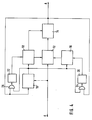
- the pulse sequences in the partial images a, b and c, which are denoted by the capital letter E, are fed to the input of the circuit shown in FIG. 4.
- the mode of operation of the circuit results from the pulse sequences shown below, which are identified by the capital letter A.
- pulses in the vicinity of an expected pulse arrive, these pulses are reproduced at output A.
- the environment of the expected pulse is limited by a time window. If no pulse falls in the time window, an artificial pulse is nevertheless generated, which replaces the non-arriving pulse in the time window.
- a pulse results in the pulse sequence denoted by A if the corresponding pulse fails in the pulse sequence denoted by E (represented by the dashed-line pulses). Pulses that are outside the time window are suppressed. This case is shown at a, where an additional interference pulse is inserted between the second, failed pulse and the third pulse.
- Fig. 1 it has been assumed that up to the first pulse at time T, which is denoted by P T , constant pulse sequences occurred. Only then does the time interval at b and c change. If the artificially generated pulse is now spaced apart from the last preceding pulses or, if the temporal sequence of preceding pulses is evaluated and extrapolated, the artificially generated pulse is spaced apart from the extrapolated one Value used, there is an equal distance T + 1 in all three cases, so that the artificially generated pulse is arranged in time as P T + 1 . Except for case a, it does not coincide with the times at which the pulses at input E would have to occur if they were present. If the limits of the time window are dimensioned accordingly and the sequence of pulses is not too large, the briefly falsified measurement result can be corrected again.
- the curve 2 shows the dependence between the lower and upper limits of the time window on the reciprocal of the time intervals between the pulses.
- the course of the curve depends on the object from which the time stamps are generated. Is it e.g. In the case of a vehicle in which the time stamps are generated in connection with the determination of a relative speed to the road surface, the curve depends on the maximum acceleration, that is to say on the road condition and the engine power, and on the maximum deceleration and thus also on the road condition.
- the values for the lower limit and upper limit can also follow different functions. It is expedient to save the determined values in a table for determining the lower limit and upper limit of the time window, and to take them from the table at given time intervals of the pulses and to use them when determining the time window.
- a time window is formed at the expected interval. This is limited by times T U as the lower limit and T O as the upper limit. Within this time window, a further pulse can occur at the time T + 1 and can be detected or can be replaced by an artificially generated pulse if it does not arrive.
- Another possibility is to evaluate and extrapolate the chronological sequence of previous pulses. Then the artificially generated pulse could be used at a distance from the extrapolated value after the last pulse. This measure makes it possible to take into account not only constant pulse sequences but also continuously reducing or increasing pulse sequences. However, cases in which there is a discontinuity are not covered.
- the upper limit T O of the time window must first be waited for before the decision can be made to insert an artificial pulse, there is no longer any possibility in the chronological sequence of inserting this pulse correctly.
- a remedy can be found in that at the time of the upper limit of the time window, the measuring device for detecting the time intervals of successive pulses is preset by the time elapsed up to the time of the upper limit. The time window for the subsequent expected pulse is then correct again.
- the circuit comprises a time measuring device 10, a time window-controlled gate circuit 12, a pulse generator 14, comparison circuits 16 and 18, and logic logic elements 24 and 26.
- the input E is connected to the time measuring device 10 via a dashed connection. This indicates that a "real" pulse must first occur at the start of a measurement so that the further process can be started. Subsequently, however, only pulses that are generated at output A are evaluated so that the time measuring device 10 is not disturbed.
- the input E is connected to the gate circuit 12, which is time-window controlled. It is monitored within the time window whether pulses occur at input E. These pulses are then passed on directly to output A. Occur within the time window If no pulses occur, a subsequent pulse generator 14 is caused to generate an artificial pulse.
- the gate circuit 12 i.e. the opening and closing, is controlled by comparison circuits 16 and 18.
- the comparison circuit 16 serves to open the gate circuit and compares a defined lower limit of the time window with the current time, while the comparison circuit 18 closes the gate circuit 12 as soon as one specified upper limit for the time window matches the current time.
- the comparison circuit 18 for the upper limit of the time window also controls the pulse generator 14 since the pulse generated by it can only be used when the time window has been waited for and the upper limit has been reached.
- the comparison circuits 16 and 18 receive the current time from the time measuring device 10 and the values for the lower and upper limits of the time window.
- memories 20 and 22 are connected to outputs of memories 20 and 22, in which the values of lower and upper limits are stored in a table.
- the memories 20 and 22 can be addressed by the time measuring device 10.
- the distance between the pulses occurring at output A is also taken into account when addressing.
- the memories 20 and 22 are supplied with the current time and the indication of the pulses occurring at the output A by logic logic elements 24 and 26.
- the pulses that can be tapped at output A can be fed to a further device in which the corresponding pulses can be processed.
Claims (9)
- Procédé de mesure sans contact de la vitesse de véhicules, selon lequel, à l'aide d'une optique on émet de la lumière vers la surface d'un revêtement de chaussée et on exploite les réflexions par rapport à une grille optique sous la forme de repères de temps se produisant en continu, pour donner des impulsions dont on mesure les intervalles de temps, procédé caractérisé en ce qu'à l'intervalle d'impulsions successives, après chaque fois la dernière impulsion, on forme une fenêtre de temps à l'intérieur de laquelle on surveille l'arrivée d'une autre impulsion et au cas où l'impulsion n'arrive pas, elle est remplacée par une impulsion de remplacement dans la fenêtre de temps, et, en fonction de la vitesse du véhicule, on décale la limite inférieure et la limite supérieure de la fenêtre de temps.
- Procédé selon la revendication 1, caractérisé en ce qu'on définit ou on calcule les valeurs d'un décalage de temps maximum des repères de temps et des impulsions qui en découlent, et en ce que l'on avance la limite inférieure de la fenêtre de temps de la valeur de l'avance de temps maximale, tandis qu'on retarde la limite supérieure de la valeur du retard de temps maximum, après l'instant prévisible d'une autre impulsion.
- Procédé selon la revendication 1 ou 2, caractérisé en ce qu'on détermine ou calcule la relation entre les intervalles de temps des impulsions et la limite inférieure ou la limite supérieure de la fenêtre de temps, et on les enregistre dans un tableau, les valeurs enregistrées des limites inférieures et supérieures étant extraites du tableau à des intervalles de temps donnés des impulsions ,et servent à fixer la fenêtre de temps.
- Procédé selon l'une des revendications 1 à 3, caractérisé en ce que, lorsque l'impulsion n'arrive pas, l'impulsion de remplacement est mise en place à la distance de la dernière impulsion précédente après la dernière impulsion dans la fenêtre de temps.
- Procédé selon l'une des revendications 1 à 3, caractérisé en ce que, lorsque l'impulsion n'arrive pas, on exploite la suite chronologique des impulsions précédentes et on extrapole et en ce qu'on place l'impulsion de remplacement en aval de la dernière impulsion dans la fenêtre de temps, à la distance correspondant à la valeur extrapolée.
- Procédé selon la revendication 4 ou 5, caractérisé en ce qu'on place l'impulsion de remplacement dans la fenêtre de temps à la limite supérieure de la fenêtre, en pré-réglant une installation de mesure détectant les intervalles de temps d'impulsions successives, du temps écoulé jusqu'à l'instant de la limite supérieure.
- Circuit de mesure sans contact de la vitesse d'un véhicule, une optique envoyant de la lumière à la surface d'un revêtement de chaussée et les réflexions étant exploitées comme des repères de temps se produisant en continu, par rapport à une grille optique, pour donner des impulsions dont on mesure les intervalles de temps, et, pour mesurer ces intervalles de temps des impulsions l'installation comprend une installation de mesure de temps (10), de préférence réalisée comme un compteur, caractérisé en ce que les impulsions sont appliquées à une porte (12) à commande de fenêtre de temps, et la porte (12) est reliée à un générateur d'impulsions (14) qui, lorsqu'une impulsion n'arrive pas, génère une impulsion de remplacement, des circuits de comparaison (16, 18) étant prévus pour comparer la limite inférieure ou la limite supérieure fixée de la fenêtre de temps, à l'instant réel, les entrées des limites inférieure et supérieure des circuits de temps (16, 18) étant reliées aux sorties des mémoires (20, 22) contenant, sous forme de tableau, les limites inférieure et supérieure, et en ce que les mémoires (20, 22) peuvent être adressées par l'installation de mesure de temps (10).
- Circuit selon la revendication 7, caractérisé en ce que la porte (12) est ouverte et fermée par les circuits de comparaison (16, 18).
- Circuit selon la revendication 7 ou 8, caractérisé en ce que le générateur d'impulsions (14) est relié à une entrée de mise à l'état de l'installation de mesure de temps (10), et en ce que l'impulsion de remplacement est utilisée à l'instant de la limite supérieure de la fenêtre de temps, en pré-réglant l'installation de mesure (10) du temps écoulé jusqu'à l'instant de la limite supérieure.
Applications Claiming Priority (2)
| Application Number | Priority Date | Filing Date | Title |
|---|---|---|---|
| DE3911830 | 1989-04-11 | ||
| DE3911830A DE3911830A1 (de) | 1989-04-11 | 1989-04-11 | Verfahren und schaltung zur auswertung von kontinuierlich auftretenden zeitmarken |
Publications (3)
| Publication Number | Publication Date |
|---|---|
| EP0392182A2 EP0392182A2 (fr) | 1990-10-17 |
| EP0392182A3 EP0392182A3 (fr) | 1991-10-09 |
| EP0392182B1 true EP0392182B1 (fr) | 1995-11-15 |
Family
ID=6378412
Family Applications (1)
| Application Number | Title | Priority Date | Filing Date |
|---|---|---|---|
| EP90103958A Expired - Lifetime EP0392182B1 (fr) | 1989-04-11 | 1990-03-01 | Procédé et circuit pour l'évaluation d'un débit continu de marques temporelles |
Country Status (2)
| Country | Link |
|---|---|
| EP (1) | EP0392182B1 (fr) |
| DE (2) | DE3911830A1 (fr) |
Families Citing this family (12)
| Publication number | Priority date | Publication date | Assignee | Title |
|---|---|---|---|---|
| DE4409241C2 (de) * | 1994-03-18 | 2002-10-31 | Corrsys Datron Sensorsysteme G | Optischer Korrelator zur berührungslosen optischen Messung von Wegen und Geschwindigkeiten relativ zueinander bewegter Objekte |
| DE19502797C1 (de) * | 1995-01-30 | 1996-05-09 | Datron Electronic Gmbh | Verfahren und Schaltung zur Filterung von Signalen |
| DE19502798A1 (de) * | 1995-01-30 | 1996-08-01 | Datron Electronic Gmbh | Schaltung und Verfahren zur Erfassung der Bewegung eines Fahrzeugs über einer Fläche |
| DE19834108C2 (de) * | 1998-07-29 | 2001-06-28 | Sican Gmbh | Verfahren zur Bestimmung der Anzahl von Motorumdrehungen bei Elektromotoren aus Stromripplen |
| DE10112230B4 (de) * | 2001-03-08 | 2005-05-04 | Pilz Gmbh & Co. | Verfahren und Vorrichtung zum fehlersicheren Überwachen der Drehbewegung einer Welle |
| EP1304578A3 (fr) * | 2001-09-28 | 2005-12-21 | Siemens Aktiengesellschaft | Procédé et dispositif pour la détermination de la vitesse angulaire d'un arbre |
| DE102004015038A1 (de) * | 2004-03-26 | 2005-10-13 | Robert Bosch Gmbh | Extrapolationsverfahren für die Drehwinkelstellung |
| DE102004057208B3 (de) * | 2004-11-26 | 2005-12-22 | Siemens Ag | Verfahren zum Erfassen von Signalen eines Kurbelwellensensors |
| FR2888687B1 (fr) * | 2005-07-13 | 2007-10-12 | Siemens Vdo Automotive Sas | Dispositif de filtrage d'un signal et procede correspondant |
| DE102005040207A1 (de) * | 2005-08-16 | 2007-02-22 | Ebm-Papst St. Georgen Gmbh & Co. Kg | Verfahren und Anordnung zur Erzeugung eines drehrichtungsabhängigen Drehzahlsignals |
| JP5256766B2 (ja) * | 2008-02-18 | 2013-08-07 | 澁谷工業株式会社 | 物品処理装置 |
| FR3067888B1 (fr) * | 2017-06-14 | 2019-06-28 | Safran Aircraft Engines | Procede de traitement d'un signal de vitesse de rotation d'un arbre de moteur d'aeronef affecte par du bruit |
Citations (2)
| Publication number | Priority date | Publication date | Assignee | Title |
|---|---|---|---|---|
| SU1064447A1 (ru) * | 1982-10-29 | 1983-12-30 | Институт Технической Кибернетики Ан Бсср | Устройство дл формировани импульсов |
| SU1338034A1 (ru) * | 1986-01-03 | 1987-09-15 | Предприятие П/Я М-5156 | Устройство дл контрол импульсных последовательностей |
Family Cites Families (6)
| Publication number | Priority date | Publication date | Assignee | Title |
|---|---|---|---|---|
| US3906346A (en) * | 1972-12-26 | 1975-09-16 | Us Navy | Precision time interval comparator |
| DE2357061C2 (de) * | 1973-11-15 | 1985-02-14 | Robert Bosch Gmbh, 7000 Stuttgart | Einrichtung zur Abgabe von gleichmäßigen Impulsen bei bestimmten Winkelstellungen einer drehbaren Welle und zur Bildung von wenigstens einem Bezugssignal |
| DE3065257D1 (en) * | 1979-05-25 | 1983-11-17 | Lucas Ind Plc | Missing pulse detector |
| FR2525005A1 (fr) * | 1982-04-13 | 1983-10-14 | Ssih Equipment Sa | Procede pour le chronometrage de competitions sportives utilisant une fenetre temporelle |
| US4628269A (en) * | 1984-05-23 | 1986-12-09 | Motorola, Inc. | Pulse detector for missing or extra pulses |
| DD226708B1 (de) * | 1984-09-03 | 1989-07-05 | Medizin Labortechnik Veb K | Schaltungsanordnung zur zuverlaessigkeitsueberwachung von drehzahlimpulsen |
-
1989
- 1989-04-11 DE DE3911830A patent/DE3911830A1/de not_active Ceased
-
1990
- 1990-03-01 EP EP90103958A patent/EP0392182B1/fr not_active Expired - Lifetime
- 1990-03-01 DE DE59009864T patent/DE59009864D1/de not_active Expired - Fee Related
Patent Citations (2)
| Publication number | Priority date | Publication date | Assignee | Title |
|---|---|---|---|---|
| SU1064447A1 (ru) * | 1982-10-29 | 1983-12-30 | Институт Технической Кибернетики Ан Бсср | Устройство дл формировани импульсов |
| SU1338034A1 (ru) * | 1986-01-03 | 1987-09-15 | Предприятие П/Я М-5156 | Устройство дл контрол импульсных последовательностей |
Also Published As
| Publication number | Publication date |
|---|---|
| EP0392182A2 (fr) | 1990-10-17 |
| DE3911830A1 (de) | 1990-10-18 |
| EP0392182A3 (fr) | 1991-10-09 |
| DE59009864D1 (de) | 1995-12-21 |
Similar Documents
| Publication | Publication Date | Title |
|---|---|---|
| EP0188433B1 (fr) | Dispositif pour detecter la position angulaire d'un organe rotatif | |
| DE60010655T2 (de) | Verfahren und vorrichtung in einem fahrzeugüberwachungssystem und fehlerdiagnosesystem in einem fahrzeug | |
| EP0392182B1 (fr) | Procédé et circuit pour l'évaluation d'un débit continu de marques temporelles | |
| EP3390967B1 (fr) | Procede de surveillance d'au moins deux capteurs redondants | |
| DE3817704C2 (fr) | ||
| DE2914072C2 (de) | Schaltungsanordnung zur Ermittlung der Periodendauer und/oder davon abgeleiteten Größen eines im wesentlichen periodischen Signals | |
| EP3282399A1 (fr) | Procede de reconnaissance ameliore d'anomalies de processus d'une installation technique et systeme de diagnostic correspondant | |
| DE4215938A1 (de) | Aussetzererkennungssystem bei einem Verbrennungsmotor | |
| DE19625896A1 (de) | Verfahren zur Erzeugung einer Warnmeldung in einer Analysevorrichtung bei Fehlfunktion einer selbsttätigen Kalibrierung | |
| EP0756156A2 (fr) | Procédé pour l'acquisition automatique des données affichées par un compteur, notamment pour l'usage de contrÔle ou calculation | |
| DE3739271A1 (de) | Einrichtung zur weg- und geschwindigkeitsmessung bei spurgebundenen fahrzeugen | |
| DE3818500A1 (de) | Fehlererkennungssystem fuer optische lichtleitersensoren | |
| DE4035520C2 (de) | Verfahren und Anordnung zur Messung der Geschwindigkeit eines Fahrzeuges | |
| DE2733689C3 (de) | Verfahren und Vorrichtung zum Erzeugen von Impulsen mit einer physikalischen Meßgröße im wesentlichen direkt proportionaler Impulsfolgefrequenz | |
| WO1999053327A1 (fr) | Procede et dispositif permettant de controler l'entrefer d'installation d'un detecteur actif | |
| EP3521792A1 (fr) | Synchronisation temporelle basée sur des événements | |
| DE2142711C3 (de) | Signalprüfschaltung für Signale, für welche bestimmte Toleranzbereiche vorgegeben sind | |
| DE3519716A1 (de) | Verfahren und vorrichtung zur auswertung einer information in frequenz und pulsbreite enthaltenden impulsfolge | |
| DE3832518C2 (de) | Verfahren und Vorrichtung zur Erkennung eines Fehlers bei einem der Geschwindigkeit eines Fahrzeugs entsprechenen Signal | |
| DE3300429A1 (de) | Einrichtung zur zuglaengenmessung | |
| DE1499399B2 (de) | Gerät zur automatischen Ermittlung der Registrierdauer eines Ereignisses aus Balkendiagrammen | |
| EP3782868A2 (fr) | Procédé d'étalonnage d'un capteur de vitesse d'un véhicule ferroviaire | |
| DE2842350C2 (de) | Schaltungsanordnung zur Überwachung von Taktimpulsfolgen | |
| DE2308304C3 (de) | Anordnung zur Schräglaufkompensation bei einem kinematischen Magnetspeicher | |
| WO1995005302A1 (fr) | Systeme de detection de roues de trains de preference a haute vitesse |
Legal Events
| Date | Code | Title | Description |
|---|---|---|---|
| PUAI | Public reference made under article 153(3) epc to a published international application that has entered the european phase |
Free format text: ORIGINAL CODE: 0009012 |
|
| AK | Designated contracting states |
Kind code of ref document: A2 Designated state(s): DE FR GB IT |
|
| PUAL | Search report despatched |
Free format text: ORIGINAL CODE: 0009013 |
|
| AK | Designated contracting states |
Kind code of ref document: A3 Designated state(s): DE FR GB IT |
|
| RAP3 | Party data changed (applicant data changed or rights of an application transferred) |
Owner name: ROBERT BOSCH GMBH |
|
| 17P | Request for examination filed |
Effective date: 19920302 |
|
| 17Q | First examination report despatched |
Effective date: 19940420 |
|
| GRAA | (expected) grant |
Free format text: ORIGINAL CODE: 0009210 |
|
| AK | Designated contracting states |
Kind code of ref document: B1 Designated state(s): DE FR GB IT |
|
| REF | Corresponds to: |
Ref document number: 59009864 Country of ref document: DE Date of ref document: 19951221 |
|
| ET | Fr: translation filed | ||
| ITF | It: translation for a ep patent filed |
Owner name: STUDIO JAUMANN |
|
| GBT | Gb: translation of ep patent filed (gb section 77(6)(a)/1977) |
Effective date: 19960122 |
|
| PLBE | No opposition filed within time limit |
Free format text: ORIGINAL CODE: 0009261 |
|
| STAA | Information on the status of an ep patent application or granted ep patent |
Free format text: STATUS: NO OPPOSITION FILED WITHIN TIME LIMIT |
|
| 26N | No opposition filed | ||
| PGFP | Annual fee paid to national office [announced via postgrant information from national office to epo] |
Ref country code: GB Payment date: 19970217 Year of fee payment: 8 |
|
| PGFP | Annual fee paid to national office [announced via postgrant information from national office to epo] |
Ref country code: FR Payment date: 19970319 Year of fee payment: 8 |
|
| PGFP | Annual fee paid to national office [announced via postgrant information from national office to epo] |
Ref country code: DE Payment date: 19970517 Year of fee payment: 8 |
|
| PG25 | Lapsed in a contracting state [announced via postgrant information from national office to epo] |
Ref country code: GB Free format text: LAPSE BECAUSE OF NON-PAYMENT OF DUE FEES Effective date: 19980301 |
|
| PG25 | Lapsed in a contracting state [announced via postgrant information from national office to epo] |
Ref country code: FR Free format text: THE PATENT HAS BEEN ANNULLED BY A DECISION OF A NATIONAL AUTHORITY Effective date: 19980331 |
|
| GBPC | Gb: european patent ceased through non-payment of renewal fee |
Effective date: 19980301 |
|
| PG25 | Lapsed in a contracting state [announced via postgrant information from national office to epo] |
Ref country code: DE Free format text: LAPSE BECAUSE OF NON-PAYMENT OF DUE FEES Effective date: 19981201 |
|
| REG | Reference to a national code |
Ref country code: FR Ref legal event code: ST |
|
| PG25 | Lapsed in a contracting state [announced via postgrant information from national office to epo] |
Ref country code: IT Free format text: LAPSE BECAUSE OF NON-PAYMENT OF DUE FEES;WARNING: LAPSES OF ITALIAN PATENTS WITH EFFECTIVE DATE BEFORE 2007 MAY HAVE OCCURRED AT ANY TIME BEFORE 2007. THE CORRECT EFFECTIVE DATE MAY BE DIFFERENT FROM THE ONE RECORDED. Effective date: 20050301 |