EP0392182B1 - Method and circuit for monitoring a continuous flow of time markings - Google Patents
Method and circuit for monitoring a continuous flow of time markings Download PDFInfo
- Publication number
- EP0392182B1 EP0392182B1 EP90103958A EP90103958A EP0392182B1 EP 0392182 B1 EP0392182 B1 EP 0392182B1 EP 90103958 A EP90103958 A EP 90103958A EP 90103958 A EP90103958 A EP 90103958A EP 0392182 B1 EP0392182 B1 EP 0392182B1
- Authority
- EP
- European Patent Office
- Prior art keywords
- time
- pulse
- pulses
- time window
- upper limit
- Prior art date
- Legal status (The legal status is an assumption and is not a legal conclusion. Google has not performed a legal analysis and makes no representation as to the accuracy of the status listed.)
- Expired - Lifetime
Links
Images

Classifications
-
- H—ELECTRICITY
- H03—ELECTRONIC CIRCUITRY
- H03K—PULSE TECHNIQUE
- H03K5/00—Manipulating of pulses not covered by one of the other main groups of this subclass
- H03K5/01—Shaping pulses
-
- G—PHYSICS
- G01—MEASURING; TESTING
- G01P—MEASURING LINEAR OR ANGULAR SPEED, ACCELERATION, DECELERATION, OR SHOCK; INDICATING PRESENCE, ABSENCE, OR DIRECTION, OF MOVEMENT
- G01P3/00—Measuring linear or angular speed; Measuring differences of linear or angular speeds
- G01P3/42—Devices characterised by the use of electric or magnetic means
- G01P3/44—Devices characterised by the use of electric or magnetic means for measuring angular speed
- G01P3/48—Devices characterised by the use of electric or magnetic means for measuring angular speed by measuring frequency of generated current or voltage
- G01P3/481—Devices characterised by the use of electric or magnetic means for measuring angular speed by measuring frequency of generated current or voltage of pulse signals
- G01P3/489—Digital circuits therefor
-
- H—ELECTRICITY
- H03—ELECTRONIC CIRCUITRY
- H03K—PULSE TECHNIQUE
- H03K5/00—Manipulating of pulses not covered by one of the other main groups of this subclass
- H03K5/19—Monitoring patterns of pulse trains
Definitions
- the invention relates to a method and a circuit for non-contact speed measurement of vehicles according to the preamble of claims 1 and 7. Time stamps that occur continuously must be evaluated.
- an autonomous location system for emergency vehicles which uses a method to record the speed, which uses an optical grating to make the relative movement to a static one rough surface, namely the road surface.
- local waves occur in proportion to the speed Filtering can be processed as speed-dependent time stamps.
- the problem described is not limited to the method for determining a speed mentioned here.
- the possibility that at continuous Occurring time stamps from which pulses are obtained, pulses are lost or pulses are inserted in the wrong place can also occur in other applications.
- a method for synchronizing transmission systems is known from SU-A-1 064 447.
- the transmission of a signal is monitored using counting pulses. If no signal appears at a given time, an alternative signal is generated.
- Another signal transmission system is known from SU-A-1 338 034. In this system, the repetition of the period of a pulse is monitored at a frequency. If a signal is missing, a corresponding replacement pulse is also formed.
- This transmission system is used for the control, processing and transmission of information. Applications in connection with a speed measurement of a vehicle are not provided.
- the invention has for its object to improve a method or a circuit of the type specified in the preamble of claims 1 and 7 in such a way that the effects of incorrectly occurring or non-occurring pulses on a measurement result are reduced or eliminated.
- the invention is based on the consideration that, in the case of a sequence of continuously occurring time stamps, abrupt changes in the temporal sequence are excluded under normal circumstances.
- a pulse following a detected pulse can and only has to occur in a limited period of time.
- the invention makes use of this by forming a time window in the time segment, in which the arrival of another pulse is monitored. As a result, pulses occurring outside of the time period and considered as disturbances according to the aforementioned considerations are masked out.
- the pulse that does not arrive is replaced by a replacement pulse - also referred to below as an artificially generated pulse - in the time window.
- This pulse forms a reference value for the further time window in which the arrival of a pulse after the next is monitored. If a further pulse is recognized in it, the evaluation of the intervals between the pulses can be continued practically without interference. It is also possible to bridge several failed pulses, provided that the intervals do not suddenly change during the failure period, so that pulses subsequently obtained from the time stamps no longer fall into the time window.
- All three pulse sequences a, b and c are continuous sequences, however in a a constant pulse sequence corresponding to a constant speed in a vehicle, in b a pulse sequence shortening in time intervals corresponding to an acceleration of the vehicle and in c a pulse sequence increasing in the intervals is shown corresponding to a deceleration of the vehicle.
- the second pulse failed, but to illustrate its location it is shown in dashed lines.
- an interference pulse is also shown between the failed second pulse and the third pulse.
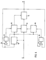
- the pulse sequences in the partial images a, b and c, which are denoted by the capital letter E, are fed to the input of the circuit shown in FIG. 4.
- the mode of operation of the circuit results from the pulse sequences shown below, which are identified by the capital letter A.
- pulses in the vicinity of an expected pulse arrive, these pulses are reproduced at output A.
- the environment of the expected pulse is limited by a time window. If no pulse falls in the time window, an artificial pulse is nevertheless generated, which replaces the non-arriving pulse in the time window.
- a pulse results in the pulse sequence denoted by A if the corresponding pulse fails in the pulse sequence denoted by E (represented by the dashed-line pulses). Pulses that are outside the time window are suppressed. This case is shown at a, where an additional interference pulse is inserted between the second, failed pulse and the third pulse.
- Fig. 1 it has been assumed that up to the first pulse at time T, which is denoted by P T , constant pulse sequences occurred. Only then does the time interval at b and c change. If the artificially generated pulse is now spaced apart from the last preceding pulses or, if the temporal sequence of preceding pulses is evaluated and extrapolated, the artificially generated pulse is spaced apart from the extrapolated one Value used, there is an equal distance T + 1 in all three cases, so that the artificially generated pulse is arranged in time as P T + 1 . Except for case a, it does not coincide with the times at which the pulses at input E would have to occur if they were present. If the limits of the time window are dimensioned accordingly and the sequence of pulses is not too large, the briefly falsified measurement result can be corrected again.
- the curve 2 shows the dependence between the lower and upper limits of the time window on the reciprocal of the time intervals between the pulses.
- the course of the curve depends on the object from which the time stamps are generated. Is it e.g. In the case of a vehicle in which the time stamps are generated in connection with the determination of a relative speed to the road surface, the curve depends on the maximum acceleration, that is to say on the road condition and the engine power, and on the maximum deceleration and thus also on the road condition.
- the values for the lower limit and upper limit can also follow different functions. It is expedient to save the determined values in a table for determining the lower limit and upper limit of the time window, and to take them from the table at given time intervals of the pulses and to use them when determining the time window.
- a time window is formed at the expected interval. This is limited by times T U as the lower limit and T O as the upper limit. Within this time window, a further pulse can occur at the time T + 1 and can be detected or can be replaced by an artificially generated pulse if it does not arrive.
- Another possibility is to evaluate and extrapolate the chronological sequence of previous pulses. Then the artificially generated pulse could be used at a distance from the extrapolated value after the last pulse. This measure makes it possible to take into account not only constant pulse sequences but also continuously reducing or increasing pulse sequences. However, cases in which there is a discontinuity are not covered.
- the upper limit T O of the time window must first be waited for before the decision can be made to insert an artificial pulse, there is no longer any possibility in the chronological sequence of inserting this pulse correctly.
- a remedy can be found in that at the time of the upper limit of the time window, the measuring device for detecting the time intervals of successive pulses is preset by the time elapsed up to the time of the upper limit. The time window for the subsequent expected pulse is then correct again.
- the circuit comprises a time measuring device 10, a time window-controlled gate circuit 12, a pulse generator 14, comparison circuits 16 and 18, and logic logic elements 24 and 26.
- the input E is connected to the time measuring device 10 via a dashed connection. This indicates that a "real" pulse must first occur at the start of a measurement so that the further process can be started. Subsequently, however, only pulses that are generated at output A are evaluated so that the time measuring device 10 is not disturbed.
- the input E is connected to the gate circuit 12, which is time-window controlled. It is monitored within the time window whether pulses occur at input E. These pulses are then passed on directly to output A. Occur within the time window If no pulses occur, a subsequent pulse generator 14 is caused to generate an artificial pulse.
- the gate circuit 12 i.e. the opening and closing, is controlled by comparison circuits 16 and 18.
- the comparison circuit 16 serves to open the gate circuit and compares a defined lower limit of the time window with the current time, while the comparison circuit 18 closes the gate circuit 12 as soon as one specified upper limit for the time window matches the current time.
- the comparison circuit 18 for the upper limit of the time window also controls the pulse generator 14 since the pulse generated by it can only be used when the time window has been waited for and the upper limit has been reached.
- the comparison circuits 16 and 18 receive the current time from the time measuring device 10 and the values for the lower and upper limits of the time window.
- memories 20 and 22 are connected to outputs of memories 20 and 22, in which the values of lower and upper limits are stored in a table.
- the memories 20 and 22 can be addressed by the time measuring device 10.
- the distance between the pulses occurring at output A is also taken into account when addressing.
- the memories 20 and 22 are supplied with the current time and the indication of the pulses occurring at the output A by logic logic elements 24 and 26.
- the pulses that can be tapped at output A can be fed to a further device in which the corresponding pulses can be processed.
Description
Die Erfindung betrifft ein Verfahren sowie eine Schaltung zur berührungslosen Geschwindingkeitsmessung von Fahrzeugen nach dem Oberbegriff der Ansprüche 1 und 7. Hierbei müssen kontinuierlich auftretende Zeitmarken ausgewertet werden.The invention relates to a method and a circuit for non-contact speed measurement of vehicles according to the preamble of
Aus der Zeitschrift "Bosch Technische Berichte", Band 8, 1986, Heft 1/2, Seiten 57 - 65 ist ein autarkes Ortungssystem für Einsatzfahrzeuge bekannt, das zur Erfassung der Geschwindigkeit ein Verfahren anwendet, das mittels eines optischen Gitters die Relativbewegung zu einer statisch rauhen Oberfläche, nämlich der Straßenoberfläche, ermittelt. Dabei treten proportional zur Geschwindigkeit Ortswellen auf, die nach einer Filterung als geschwindigkeitsabhängige Zeitmarken verarbeitet werden können. Der Vorteil dieses Verfahrens besteht darin, daß unabhängig vom Reifenverschleiß und Luftdruck die Geschwindigkeit mit gleichbleibender Genauigkeit und sehr hoher Präzision erfaßt werden kann.From the magazine "Bosch Technical Reports", Volume 8, 1986,
Nachteilig ist es jedoch, daß bei optisch ungünstiger Ausbildung der Oberflächen oder einer Änderung des Straßenbelages die Amplitude der Ortswellen abnehmen kann, so daß sich aus den Zeitmarken keine Pulse für die Messung der Abstände gewinnen lassen oder daß einzelne Pulse in einer Folge von Pulsen ausfallen.It is disadvantageous, however, that if the surfaces are optically unfavorable or the road surface changes, the amplitude of the local waves can decrease, so that no pulses for measuring the distances can be obtained from the time stamps, or that individual pulses fail in a sequence of pulses.
Bei der Auswertung der Pulse würde dies zu einer sprunghaften Änderung der aus den Abständen der Pulse gewonnenen Größe, z.B. der Geschwindigkeit führen. Eine in anderer Richtung wirkende Änderung kann eintreten, wenn zusätzlich zu der kontinuierlichen Folge der Zeitmarken und der daraus gewonnenen Pulse durch Störeinflüsse ein oder mehrere Pulse als zusätzliche Störpulse erscheinen.When evaluating the pulses, this would lead to a sudden change in the size obtained from the intervals between the pulses, e.g. of speed. A change acting in a different direction can occur if, in addition to the continuous sequence of the time stamps and the pulses obtained therefrom, one or more pulses appear as additional interference pulses.
Die beschriebene Problematik ist nicht auf das hier angesprochene Verfahren zur Ermittlung einer Geschwindigkeit beschränkt. Die Möglichkeit, daß bei kontinuierlich auftretenden Zeitmarken, aus denen Pulse gewonnen werden, Pulse verloren gehen oder Pulse an falscher Stelle eingefügt werden, kann auch bei anderen Anwendungsfällen auftreten.The problem described is not limited to the method for determining a speed mentioned here. The possibility that at continuous Occurring time stamps from which pulses are obtained, pulses are lost or pulses are inserted in the wrong place can also occur in other applications.
Aus der SU-A-1 064 447 ist ein Verfahren zur Synchronisation von Übertragungssystemen bekannt. Dabei wird die Übertragung eines Signals mit Hilfe von Zählimpulsen überwacht. Erscheint zu einem vorgegebenen Zeitpunkt kein Signal, dann wird ein Ersatzsignal gebildet. Ein weiteres Signal-Übertragungssystem ist aus der SU-A-1 338 034 bekannt. Bei diesem System wird bei einer Frequenz die Wiederholung der Periode eines Pulses überwacht. Fehlt ein Signal, dann wird ebenfalls ein entsprechender Ersatzimpuls gebildet. Dieses Übertragungssystem wird zur Steuerung, Verarbeitung und Übertragung von Informationen verwendet. Anwendungen in Verbindung mit einer Geschwindigkeitsmessung eines Fahrzeuges sind nicht vorgesehen.A method for synchronizing transmission systems is known from SU-A-1 064 447. The transmission of a signal is monitored using counting pulses. If no signal appears at a given time, an alternative signal is generated. Another signal transmission system is known from SU-A-1 338 034. In this system, the repetition of the period of a pulse is monitored at a frequency. If a signal is missing, a corresponding replacement pulse is also formed. This transmission system is used for the control, processing and transmission of information. Applications in connection with a speed measurement of a vehicle are not provided.
Der Erfindung liegt die Aufgabe zugrunde, ein Verfahren bzw. eine Schaltung der im Oberbegriff der Ansprüche 1 bzw. 7 angegebenen Art, dahingehend zu verbessern, daß die Auswirkungen fehlerhaft auftretender oder nicht auftretender Pulse auf ein Meßergebnis verringert oder beseitigt werden.The invention has for its object to improve a method or a circuit of the type specified in the preamble of
Diese Aufgabe wird durch die im kennzeichnenden Teil der Ansprüche 1 bzw. 7 angegebenen Merkmale gelöst.This object is achieved by the features specified in the characterizing part of
Die Erfindung geht von der Überlegung aus, daß bei einer Folge von kontinuierlich auftretenden Zeitmarken unter normalen Umständen abrupte Änderungen der zeitlichen Folge ausgeschlossen sind.The invention is based on the consideration that, in the case of a sequence of continuously occurring time stamps, abrupt changes in the temporal sequence are excluded under normal circumstances.
Dementsprechend kann und muß ein auf einen erkannten Puls nachfolgender Puls nur in einem begrenzten Zeitabschnitt auftreten. Die Erfindung nutzt dies, indem in dem Zeitabschnitt ein Zeitfenster gebildet wird, in dem das Eintreffen eines weiteren Pulses überwacht wird. Dadurch werden außerhalb des Zeitabschnittes auftretende und nach den vorgenannten Überlegungen als Störungen betrachtete Pulse ausgeblendet.Accordingly, a pulse following a detected pulse can and only has to occur in a limited period of time. The invention makes use of this by forming a time window in the time segment, in which the arrival of another pulse is monitored. As a result, pulses occurring outside of the time period and considered as disturbances according to the aforementioned considerations are masked out.
Um den weiteren Fehler zu beseitigen, daß ein im Zeitfenster erwarteter Puls völlig ausfällt, wird der nicht eintreffen Puls durch einen Ersatzpuls - nachfolgend auch als künstlich erzeugter Puls bezeichnet - im Zeitfenster ersetzt. Dieser Puls bildet dann einen Bezugswert für das weitere Zeitfenster, in dem das Eintreffen eines übernächsten Pulses überwacht wird. Wenn darin ein weiterer Puls erkannt wird, kann die Auswertung der Abstände der Pulse praktisch ohne Störungen fortgesetzt werden. Auch die Überbrückung mehrerer ausgefallener Pulse ist möglich unter der Voraussetzung, daß sich während der Ausfallperiode die Abstände nicht plötzlich ändern, so daß anschließend aus den Zeitmarken gewonnene Pulse nicht mehr in das Zeitfenster fallen.In order to eliminate the further error that a pulse expected in the time window fails completely, the pulse that does not arrive is replaced by a replacement pulse - also referred to below as an artificially generated pulse - in the time window. This pulse then forms a reference value for the further time window in which the arrival of a pulse after the next is monitored. If a further pulse is recognized in it, the evaluation of the intervals between the pulses can be continued practically without interference. It is also possible to bridge several failed pulses, provided that the intervals do not suddenly change during the failure period, so that pulses subsequently obtained from the time stamps no longer fall into the time window.
Weiterbildungen der Erfindung sehen vor, daß die Untergrenze und die Obergrenze des Zeitfensters in Abhängigkeit der zeitlichen Folge der Pulse verschoben werden können.Further developments of the invention provide that the lower limit and the upper limit of the time window can be shifted depending on the temporal sequence of the pulses.
Im Hinblick auf die Möglichkeit, die Erfindung bei der berührungslosen Geschwindigkeitsmessung von Fahrzeugen einzusetzen, berücksichtigt diese Weiterbildung, daß sich die maximale Beschleunigung oder Verzögerung des Fahrzeugs in Abhängigkeit der jeweiligen Geschwindigkeit ändert.With regard to the possibility of using the invention in the contactless speed measurement of vehicles, this development takes into account that the maximum acceleration or deceleration of the vehicle changes depending on the respective speed.
Weiterbildungen und vorteilhafte Ausgestaltungen der Erfindung ergeben sich aus den Ansprüchen, der Beschreibung und der Zeichnung, anhand der die Erfindung näher erläutert ist.Further developments and advantageous refinements of the invention result from the claims, the description and the drawing, on the basis of which the invention is described in more detail is explained.
In der Zeichnung zeigen:
- Fig. 1
- Pulsfolgen mit Störpulsen oder ausgefallenen Pulsen am Eingang und Ausgang einer Schaltung nach der Erfindung,
- Fig. 2
- eine Funktion zur Darstellung der Abhängigkeit von Untergrenzen und Obergrenzen des Zeitfensters in Bezug auf den Kehrwert der zeitlichen Abstände der Pulse,
- Fig. 3
- eine Darstellung der Zeitpunkte einer Pulsfolge mit Ober- und Untergrenzen eines Zeitfensters, und
- Fig. 4
- eine Schaltung nach der Erfindung.
- Fig. 1
- Pulse sequences with interference pulses or failed pulses at the input and output of a circuit according to the invention,
- Fig. 2
- a function for displaying the dependency of lower and upper limits of the time window in relation to the reciprocal of the time intervals of the pulses,
- Fig. 3
- a representation of the times of a pulse train with upper and lower limits of a time window, and
- Fig. 4
- a circuit according to the invention.
In Fig. 1 a - c sind verschiedene Pulsfolgen, jeweils am Eingang E und Ausgang A einer noch zu erläuternden und in Fig. 4 dargestellten Schaltung gezeigt.1 a - c are different pulse sequences, each at the input E and output A of a circuit to be explained and shown in FIG. 4.
Es handelt sich bei allen drei Pulsfolgen a, b und c um kontinuierliche Folgen, wobei jedoch in a eine konstante Pulsfolge entsprechend einer konstanten Geschwindigkeit bei einem Fahrzeug, in b eine sich in den zeitlichen Abständen verkürzende Pulsfolge entsprechend einer Beschleunigung des Fahrzeugs sowie in c eine sich in den Abständen vergrößernde Pulsfolge entsprechend einer Verzögerung des Fahrzeugs dargestellt ist. In den Beispielen a, b und c ist jeweils der zweite Puls ausgefallen, zur Verdeutlichung seiner örtlichen Anordnung aber gestrichelt dargestellt. In a ist zusätzlich zwischen dem ausgefallenen zweiten Puls und dem dritten Puls noch ein Störpuls dargestellt.All three pulse sequences a, b and c are continuous sequences, however in a a constant pulse sequence corresponding to a constant speed in a vehicle, in b a pulse sequence shortening in time intervals corresponding to an acceleration of the vehicle and in c a pulse sequence increasing in the intervals is shown corresponding to a deceleration of the vehicle. In examples a, b and c, the second pulse failed, but to illustrate its location it is shown in dashed lines. In a, an interference pulse is also shown between the failed second pulse and the third pulse.
Die Pulsfolgen in den Teilbildern a, b und c, welche mit dem großen Buchstaben E bezeichnet sind, werden dem Eingang der in Fig. 4 dargestellten Schaltung zugeführt. Die Wirkungsweise der Schaltung ergibt sich aus den jeweils darunter gezeichneten Pulsfolgen, die mit dem großen Buchstaben A bezeichnet sind. Solange Pulse in der Umgebung eines erwarteten Pulses eintreffen, werden diese Pulse am Ausgang A wiedergegeben. Die Umgebung des erwarteten Pulses ist dabei durch ein Zeitfenster begrenzt. Fällt in das Zeitfenster kein Puls, so wird dennoch ein künstlicher Puls erzeugt, der den nicht eintreffenden Puls im Zeitfenster ersetzt.The pulse sequences in the partial images a, b and c, which are denoted by the capital letter E, are fed to the input of the circuit shown in FIG. 4. The mode of operation of the circuit results from the pulse sequences shown below, which are identified by the capital letter A. As long as pulses in the vicinity of an expected pulse arrive, these pulses are reproduced at output A. The environment of the expected pulse is limited by a time window. If no pulse falls in the time window, an artificial pulse is nevertheless generated, which replaces the non-arriving pulse in the time window.
Somit ergibt sich bei den Darstellungen in Fig. 1 auch dann ein Puls bei der mit A bezeichneten Pulsfolge, wenn der entsprechende Puls bei der mit E bezeichneten Pulsfolge ausfällt (durch die gestrichelt gezeichneten Pulse dargestellt). Pulse, die außerhalb des Zeitfensters liegen, werden unterdrückt. Dieser Fall ist bei a dargestellt, wo zwischen dem zweiten, ausgefallenen Puls und dem dritten Puls ein zusätzlicher Störpuls eingefügt ist.Thus, in the representations in FIG. 1, a pulse results in the pulse sequence denoted by A if the corresponding pulse fails in the pulse sequence denoted by E (represented by the dashed-line pulses). Pulses that are outside the time window are suppressed. This case is shown at a, where an additional interference pulse is inserted between the second, failed pulse and the third pulse.
In Fig. 1 ist davon ausgegangen, daß bis zu dem ersten Puls im Zeitpunkt T der mit PT bezeichnet ist, konstante Pulsfolgen auftraten. Erst danach findet eine Änderung der zeitlichen Abstände bei b und c statt. Wird der künstlich erzeugte Puls nun im Abstand der letzten vorangehenden Pulse oder, falls die zeitliche Folge vorangehender Pulse ausgewertet und extrapoliert wird, der künstlich erzeugte Puls im Abstand des extrapolierten Wertes eingesetzt, so ergibt sich in allen drei Fällen ein gleicher Abstand T+1, so daß der künstlich erzeugte Puls als PT+1 zeitlich angeordnet wird. Bis auf den Fall a fällt er nicht mit dem Zeitpunkten zusammen, bei denen die Pulse am Eingang E bei Vorhandensein auftreten müßten. Wenn die Grenzen des Zeitfensters entsprechend bemessen sind und nicht eine zu große Folge von Pulsen ausfällt, kann das kurzzeitig geringfügige verfälschte Meßergebnis wieder korrigiert werden.In Fig. 1 it has been assumed that up to the first pulse at time T, which is denoted by P T , constant pulse sequences occurred. Only then does the time interval at b and c change. If the artificially generated pulse is now spaced apart from the last preceding pulses or, if the temporal sequence of preceding pulses is evaluated and extrapolated, the artificially generated pulse is spaced apart from the extrapolated one Value used, there is an equal distance T + 1 in all three cases, so that the artificially generated pulse is arranged in time as P T + 1 . Except for case a, it does not coincide with the times at which the pulses at input E would have to occur if they were present. If the limits of the time window are dimensioned accordingly and the sequence of pulses is not too large, the briefly falsified measurement result can be corrected again.
In Fig. 2 ist die Abhängigkeit zwischen den Unter- und Obergrenzen des Zeitfensters zum Kehrwert der zeitlichen Abstände zwischen den Pulsen dargestellt. Der Verlauf der Kurve ist abhängig davon, von welchem Objekt die Zeitmarken erzeugt werden. Handelt es sich z.B. um ein Fahrzeug, bei dem die Zeitmarken im Zusammenhang mit der Ermittlung einer Relativgeschwindigkeit zur Fahrbahnoberfläche erzeugt werden, so ist die Kurve von der maximalen Beschleunigung, also vom Straßenzustand sowie der Motorleistung abhängig und von der maximalen Verzögerung und damit ebenfalls vom Straßenzustand.2 shows the dependence between the lower and upper limits of the time window on the reciprocal of the time intervals between the pulses. The course of the curve depends on the object from which the time stamps are generated. Is it e.g. In the case of a vehicle in which the time stamps are generated in connection with the determination of a relative speed to the road surface, the curve depends on the maximum acceleration, that is to say on the road condition and the engine power, and on the maximum deceleration and thus also on the road condition.
Die Werte für die Untergrenze und Obergrenze können auch unterschiedlichen Funktionen folgen. Es ist zweckmäßig, zur Bestimmung der Untergrenze und Obergrenze des Zeitfensters die ermittelten Werte in einer Tabelle zu speichern und bei gegebenen zeitlichen Abständen der Pulse sie der Tabelle zu entnehmen und bei Festlegung des Zeitfensters einzusetzen.The values for the lower limit and upper limit can also follow different functions. It is expedient to save the determined values in a table for determining the lower limit and upper limit of the time window, and to take them from the table at given time intervals of the pulses and to use them when determining the time window.
In Fig. 3 sind Zeitpunkte für das Eintreffen von Pulsen sowie für die Ober- und Untergrenze eines Zeitfensters eingetragen. Ausgehend von einem Zeitpunkt T, in dem ein Puls entweder ermittelt oder künstlich erzeugt wird, wird im erwarteten Abstand ein Zeitfenster gebildet. Dieses ist durch Zeitpunkte TU als Untergrenze und TO als Obergrenze begrenzt. Innerhalb dieses Zeitfensters kann ein weiterer Puls im Zeitpunkt T+1 auftreten und erfaßt werden oder bei nicht Eintreffen durch einen künstlich erzeugten Puls ersetzt werden.3 shows times for the arrival of pulses as well as for the upper and lower limits of a time window. Starting from a point in time T at which a pulse is either determined or generated artificially, a time window is formed at the expected interval. This is limited by times T U as the lower limit and T O as the upper limit. Within this time window, a further pulse can occur at the time T + 1 and can be detected or can be replaced by an artificially generated pulse if it does not arrive.
Im Falle eines künstlich erzeugten Pulses besteht noch das Problem, wohin dieser innerhalb des Zeitfensters versetzt werden soll. Im einfachsten Fall könnte dies dadurch gelöst werden, daß der Abstand der letzten vorangehenden Pulse bestimmt wird und der künstlich erzeugte Puls in dem selben Abstand nach dem letzten Puls eingesetzt wird. Bei gleichbleibender Pulsfolge wäre diese Maßnahme korrekt, bei sich ändernder Pulsfolge würde dagegen ein Fehler auftreten.In the case of an artificially generated pulse, there is still the problem of where it should be moved within the time window. In the simplest case, this could be solved by determining the distance between the last preceding pulses and using the artificially generated pulse at the same distance after the last pulse. If the pulse sequence remained the same, this would be Correct measure, an error would occur if the pulse train changed.
Eine andere Möglichkeit besteht darin, die zeitliche Folge vorhergehender Pulse auszuwerten und zu extrapolieren. Dann könnte der künstlich erzeugte Puls im Abstand des extrapolierten Wertes nach dem letzten Puls eingesetzt werden. Durch diese Maßnahme besteht die Möglichkeit, neben konstanten Pulsfolgen auch stetig verkleinernde oder vergrößernde Pulsfolgen zu berücksichtigen. Nicht erfaßt werden jedoch Fälle, in denen eine Unstetigkeit vorliegt.Another possibility is to evaluate and extrapolate the chronological sequence of previous pulses. Then the artificially generated pulse could be used at a distance from the extrapolated value after the last pulse. This measure makes it possible to take into account not only constant pulse sequences but also continuously reducing or increasing pulse sequences. However, cases in which there is a discontinuity are not covered.
Da in der Praxis im zeitlichen Ablauf erst die Obergrenze TO des Zeitfensters abgewartet werden muß, ehe über die Einfügung eines künstlichen Pulses entschieden werden kann, besteht im zeitlichen Ablauf nicht mehr die Möglichkeit, diesen Puls noch zeitrichtig einzufügen. Eine Abhilfe läßt sich dadurch schaffen, daß im Zeitpunkt der Obergrenze des Zeitfensters die Meßeinrichtung zum Erfassen der zeitlichen Abstände aufeinanderfolgender Pulse um die bis zum Zeitpunkt der Obergrenze verstrichene Zeit voreingestellt wird. Das Zeitfenster für den nachfolgenden zu erwartenden Puls liegt dann wieder richtig.Since, in practice, the upper limit T O of the time window must first be waited for before the decision can be made to insert an artificial pulse, there is no longer any possibility in the chronological sequence of inserting this pulse correctly. A remedy can be found in that at the time of the upper limit of the time window, the measuring device for detecting the time intervals of successive pulses is preset by the time elapsed up to the time of the upper limit. The time window for the subsequent expected pulse is then correct again.
Fig. 4 zeigt schließlich eine Schaltung zur Auswertung von kontinuierlich auftretenden Zeitmarken nach der Erfindung. Dabei werden Pulse, die aus Zeitmarken gewonnen werden und in deren zeitlicher Folge auch Pulse ausfallen oder Störpulse zusätzlich auftreten können, über einen Eingang E eingespeist und eine kontinuierlich auftretende Folge von Pulsen ist am Ausgang A abgreifbar. Die Schaltung umfaßt eine Zeitmeßeinrichtung 10, eine zeitfenstergesteuerte Torschaltung 12, einen Pulsgenerator 14, Vergleichsschaltungen 16 und 18 sowie logische Verknüpfungsglieder 24 und 26.4 finally shows a circuit for evaluating continuously occurring time stamps according to the invention. In this case, pulses which are obtained from time stamps and in the chronological order of which pulses also fail or interference pulses can additionally occur are fed in via an input E and a continuously occurring sequence of pulses can be tapped off at output A. The circuit comprises a
Der Eingang E ist über eine gestrichelte Verbindung mit der Zeitmeßeinrichtung 10 verbunden. Damit ist angedeutet, daß bei Beginn einer Messung zunächst ein "echter" Puls auftreten muß, damit das weitere Verfahren in Gang gesetzt werden kann. Anschließend werden jedoch nur Pulse ausgewertet, die am Ausgang A erzeugt werden, damit die Zeitmeßeinrichtung 10 nicht gestört wird.The input E is connected to the
Der Eingang E ist mit der Torschaltung 12 verbunden, die zeitfenstergesteuert ist. Innerhalb des Zeitfensters wird überwacht, Ob Pulse am Eingang E auftreten. Diese Pulse werden dann unmittelbar an den Ausgang A weitergegeben. Treten innerhalb des Zeitfensters keine Pulse auf, so wird ein nachfolgender Pulsgenerator 14 veranlaßt, einen künstlichen Puls zu erzeugen.The input E is connected to the
Die Steuerung der Torschaltung 12, also das Öffnen und Schließen erfolgt durch Vergleichsschaltungen 16 und 18. Dabei dient die Vergleichsschaltung 16 zur Öffnung der Torschaltung und vergleicht eine festgelegte Untergrenze des Zeitfensters mit der aktuellen Zeit, während die Vergleichsschaltung 18 die Torschaltung 12 schließt, sobald eine festgelegte Obergrenze für das Zeitfenster mit der aktuellen Zeit übereinstimmt.The
Von der Vergleichsschaltung 18 für die Obergrenze des Zeitfensters wird außerdem der Pulsgenerator 14 gesteuert, da der von diesem erzeugte Puls erst dann eingesetzt werden kann, wenn das Zeitfenster abgewartet wurde und die Obergrenze erreicht ist.The
Die Vergleichsschaltungen 16 und 18 erhalten einmal von der Zeitmeßeinrichtung 10 die aktuelle Zeit und zum anderen die Werte für die Unter- und Obergrenzen des Zeitfensters.The
Dazu sind ihre Eingänge mit Ausgängen von Speichern 20 und 22 verbunden, in denen die Werte von Unter und Obergrenzen tabellarisch gespeichert sind. Die Speicher 20 und 22 sind durch die Zeitmeßeinrichtung 10 adressierbar. Zusätzlich wird bei der Adressierung auch der Abstand der am Ausgang A auftretenden Pulse berücksichtigt. Dementsprechend wird den Speichern 20 und 22 die aktuelle Zeit sowie die Angabe der am Ausgang A auftretenden Pulse durch logische Verknüpfungsglieder 24 und 26 zugeführt.For this purpose, their inputs are connected to outputs of
Falls aus den zeitlichen Abständen der Pulse und damit der Zeitmarken Werte für eine Geschwindigkeit ermittelt werden sollen, kann dies auch durch die Zeitmeßeinrichtung 10 durchgeführt werden. Ansonsten lassen sich die am Ausgang A abgreifbaren Pulse einer weiteren Einrichtung zuführen, in der die entsprechenden Pulse verarbeitet werden können.If values for a speed are to be determined from the time intervals of the pulses and thus the time marks, this can also be carried out by the
Die Schaltung gemäß Fig. 4 ist eine mögliche Ausgestaltung zur Durchführung der Auswertung von kontinuierlich auftretenden Zeitmarken. Es besteht auch die Möglichkeit, die in der Schaltung durch diskrete Schaltungselemente ausgeführten Funktionen mit Hilfe eines Rechners durchzuführen, indem die Funktionen programmge steuert simuliert und durchlaufen werden.4 is a possible embodiment for carrying out the evaluation of continuously occurring time stamps. There is also the possibility of performing the functions carried out in the circuit by discrete circuit elements with the aid of a computer, by programming the functions controls are simulated and run through.
Claims (9)
- Method for the contactless speed measurement of vehicles, light being transmitted onto the surface of a road surface by means of optics, and the reflections being evaluated with respect to an optical grid as continuously occurring time markings, from which pulses are obtained and their time spacings are measured, characterized in that, at the spacing of successive pulses, after the last pulse in each case, a time window is formed within which the arrival of a further pulse is monitored, and in that in the event of the non-arrival of the pulse, this is substituted by a substitute pulse in the time window, the lower limit and the upper limit of the time window being shifted as a function of the speed of the vehicle.
- Method according to Claim 1, characterized in that values for a maximum time shift of the time markings and of the pulses obtained therefrom are determined or calculated, and in that the lower limit of the time window is set by the value of the maximum time lead before and the upper limit by the value of the maximum time lag after the expected instant of a further pulse.
- Method according to Claim 1 or 2, characterized in that the relationship between the time spacings of the pulses and the lower limit or the upper limit of the time window is determined or calculated and stored in a table, and in that the stored values of the lower limit and of the upper limit, in the event of given time spacings of the pulses, are taken from the table and used in fixing the time window.
- Method according to one of Claims 1 to 3, characterized in that in the event of the non-arrival of the pulse, the substitute pulse is used in the time window after the last pulse at the spacing of the last previous pulse.
- Method according to one of Claims 1 to 3, characterized in that, in the event of the non-arrival of the pulse, the time sequence of previous pulses is evaluated and extrapolated, and in that the substitute pulse is used in the time window after the last pulse at the spacing of the extrapolated value.
- Method according to Claim 4 or 5, characterized in that the substitute pulse is used in the time window of the upper limit of the time window, in that a measuring device registering the time spacings of successive pulses is preset by the time which has elapsed until the instant of the upper limit.
- Circuit for the contactless speed measurement of vehicles, light being transmitted onto the surface of a road surface by means of optics, and the reflections being able to be evaluated with respect to an optical grid as continuously occurring time markings, from which pulses are obtained and their time spacings are measured, a time measuring device (10), preferably designed as a counter, being provided to measure the time spacings of the pulses, characterized in that the pulses are fed to a time-window-controlled gate circuit (12), in that the gate circuit (12) is connected to a pulse generator (14) which, in the event of the non-arrival of a pulse, generates a substitute pulse, in that comparison circuits (16, 18) are provided, which compare fixed lower limits and upper limits for the time window with the current time, the inputs for the lower and upper limits of the comparison circuits (16, 18) being connected to outputs of stores (20, 22) in which values of lower and upper limits are stored in tabular form, and in that the stores (20, 22) can be addressed by the time measuring device (10) .
- Circuit according to Claim 7, characterized in that the gate circuit (12) can be opened and closed by the comparison circuits (16, 18).
- Circuit according to Claim 7 or 8, characterized in that the pulse generator (14) is connected to a set input of the time measuring device (10), and in that the substitute pulse is used at the instant of the upper limit of the time window, in that the measuring device (10) is preset by the time which has elapsed until the instant of the upper limit.
Applications Claiming Priority (2)
| Application Number | Priority Date | Filing Date | Title |
|---|---|---|---|
| DE3911830A DE3911830A1 (en) | 1989-04-11 | 1989-04-11 | METHOD AND CIRCUIT FOR EVALUATING CONTINUOUSLY APPEARING TIMES |
| DE3911830 | 1989-04-11 |
Publications (3)
| Publication Number | Publication Date |
|---|---|
| EP0392182A2 EP0392182A2 (en) | 1990-10-17 |
| EP0392182A3 EP0392182A3 (en) | 1991-10-09 |
| EP0392182B1 true EP0392182B1 (en) | 1995-11-15 |
Family
ID=6378412
Family Applications (1)
| Application Number | Title | Priority Date | Filing Date |
|---|---|---|---|
| EP90103958A Expired - Lifetime EP0392182B1 (en) | 1989-04-11 | 1990-03-01 | Method and circuit for monitoring a continuous flow of time markings |
Country Status (2)
| Country | Link |
|---|---|
| EP (1) | EP0392182B1 (en) |
| DE (2) | DE3911830A1 (en) |
Families Citing this family (12)
| Publication number | Priority date | Publication date | Assignee | Title |
|---|---|---|---|---|
| DE4409241C2 (en) * | 1994-03-18 | 2002-10-31 | Corrsys Datron Sensorsysteme G | Optical correlator for non-contact optical measurement of paths and speeds of objects moving relative to each other |
| DE19502798A1 (en) * | 1995-01-30 | 1996-08-01 | Datron Electronic Gmbh | Vehicle movement detecting circuit e.g. for speed measurement |
| DE19502797C1 (en) * | 1995-01-30 | 1996-05-09 | Datron Electronic Gmbh | Signal filtering method, pref. for vehicle motion sensor signals |
| DE19834108C2 (en) * | 1998-07-29 | 2001-06-28 | Sican Gmbh | Method for determining the number of motor revolutions in electric motors from current ripples |
| DE10112230B4 (en) * | 2001-03-08 | 2005-05-04 | Pilz Gmbh & Co. | Method and device for fail-safe monitoring of the rotational movement of a shaft |
| EP1304578A3 (en) * | 2001-09-28 | 2005-12-21 | Siemens Aktiengesellschaft | Method and device for the determination of the angular speed of a shaft |
| DE102004015038A1 (en) * | 2004-03-26 | 2005-10-13 | Robert Bosch Gmbh | Extrapolation method for the angular position |
| DE102004057208B3 (en) * | 2004-11-26 | 2005-12-22 | Siemens Ag | Signal processing circuit for crankshaft angle sensor for internal combustion engine identifies first signal flank after reference gap in toothed wheel generating position signal |
| FR2888687B1 (en) * | 2005-07-13 | 2007-10-12 | Siemens Vdo Automotive Sas | DEVICE FOR FILTERING A SIGNAL AND CORRESPONDING METHOD |
| DE102005040207A1 (en) * | 2005-08-16 | 2007-02-22 | Ebm-Papst St. Georgen Gmbh & Co. Kg | Turning direction dependent revolution speed signal generating method e.g. for production of direction-controlled velocity signals, involves producing several impulses per time unit, proportional to speed of arrangement |
| JP5256766B2 (en) * | 2008-02-18 | 2013-08-07 | 澁谷工業株式会社 | Article processing equipment |
| FR3067888B1 (en) * | 2017-06-14 | 2019-06-28 | Safran Aircraft Engines | METHOD FOR PROCESSING A ROTATION SPEED SIGNAL OF A NOISE AFFECTED AIRCRAFT ENGINE SHAFT |
Citations (2)
| Publication number | Priority date | Publication date | Assignee | Title |
|---|---|---|---|---|
| SU1064447A1 (en) * | 1982-10-29 | 1983-12-30 | Институт Технической Кибернетики Ан Бсср | Device for shaping pulses |
| SU1338034A1 (en) * | 1986-01-03 | 1987-09-15 | Предприятие П/Я М-5156 | Device for checking pulse sequences |
Family Cites Families (6)
| Publication number | Priority date | Publication date | Assignee | Title |
|---|---|---|---|---|
| US3906346A (en) * | 1972-12-26 | 1975-09-16 | Us Navy | Precision time interval comparator |
| DE2357061C2 (en) * | 1973-11-15 | 1985-02-14 | Robert Bosch Gmbh, 7000 Stuttgart | Device for the delivery of uniform pulses at certain angular positions of a rotatable shaft and for the formation of at least one reference signal |
| DE3065257D1 (en) * | 1979-05-25 | 1983-11-17 | Lucas Ind Plc | Missing pulse detector |
| FR2525005A1 (en) * | 1982-04-13 | 1983-10-14 | Ssih Equipment Sa | METHOD FOR TIMING SPORTS COMPETITIONS USING A TIME WINDOW |
| US4628269A (en) * | 1984-05-23 | 1986-12-09 | Motorola, Inc. | Pulse detector for missing or extra pulses |
| DD226708B1 (en) * | 1984-09-03 | 1989-07-05 | Medizin Labortechnik Veb K | CIRCUIT ARRANGEMENT FOR THE RELIABILITY MONITORING OF SPEED PULSES |
-
1989
- 1989-04-11 DE DE3911830A patent/DE3911830A1/en not_active Ceased
-
1990
- 1990-03-01 DE DE59009864T patent/DE59009864D1/en not_active Expired - Fee Related
- 1990-03-01 EP EP90103958A patent/EP0392182B1/en not_active Expired - Lifetime
Patent Citations (2)
| Publication number | Priority date | Publication date | Assignee | Title |
|---|---|---|---|---|
| SU1064447A1 (en) * | 1982-10-29 | 1983-12-30 | Институт Технической Кибернетики Ан Бсср | Device for shaping pulses |
| SU1338034A1 (en) * | 1986-01-03 | 1987-09-15 | Предприятие П/Я М-5156 | Device for checking pulse sequences |
Also Published As
| Publication number | Publication date |
|---|---|
| DE3911830A1 (en) | 1990-10-18 |
| DE59009864D1 (en) | 1995-12-21 |
| EP0392182A2 (en) | 1990-10-17 |
| EP0392182A3 (en) | 1991-10-09 |
Similar Documents
| Publication | Publication Date | Title |
|---|---|---|
| EP0188433B1 (en) | Device for detecting the angular position of a rotary member | |
| DE60010655T2 (en) | METHOD AND DEVICE IN A VEHICLE MONITORING SYSTEM AND TROUBLE DIAGNOSIS SYSTEM IN A VEHICLE | |
| EP0392182B1 (en) | Method and circuit for monitoring a continuous flow of time markings | |
| DE3817704C2 (en) | ||
| EP3390967B1 (en) | Method for monitoring at least two redundant sensors | |
| DE2914072C2 (en) | Circuit arrangement for determining the period duration and / or quantities derived therefrom of an essentially periodic signal | |
| EP3282399A1 (en) | Method for the improved detection of process anomalies of a technical installation and corresponding diagnostic system | |
| DE4215938A1 (en) | Misfire detection system for vehicle IC engine - compares wheel irregularity value derived from rotation rate with threshold value and blocks misfire detection if threshold is exceeded. | |
| DE19625896A1 (en) | Warning of impending failure in auto-calibration system of e.g. gas analysis instruments | |
| EP0756156A2 (en) | Method for the automatic acquisition of data displayed on a counter, for test or calculation purposes | |
| DE3739271A1 (en) | DEVICE FOR TRAVEL AND SPEED MEASUREMENT IN TRACKED VEHICLES | |
| DE3818500A1 (en) | ERROR DETECTION SYSTEM FOR OPTICAL LIGHT SENSORS | |
| DE4035520C2 (en) | Method and arrangement for measuring the speed of a vehicle | |
| DE2733689C3 (en) | Method and device for generating pulses with a physical measured variable, essentially directly proportional pulse repetition frequency | |
| WO1999053327A1 (en) | Method and device for checking the installation air gap of an active sensor | |
| EP3521792A1 (en) | Event-based temporal synchronization | |
| DE2142711C3 (en) | Signal test circuit for signals for which certain tolerance ranges are specified | |
| DE3519716A1 (en) | METHOD AND DEVICE FOR EVALUATING AN IMPULSE SEQUENCE CONTAINING INFORMATION IN FREQUENCY AND PULSE WIDTH | |
| DE3832518C2 (en) | Method and device for detecting an error in a signal corresponding to the speed of a vehicle | |
| DE1499399B2 (en) | Device for the automatic determination of the recording duration of an event from bar graphs | |
| EP3782868A2 (en) | Method for calibrating a speed sensor of a railway vehicle | |
| DE2842350C2 (en) | Circuit arrangement for monitoring clock pulse trains | |
| EP0629965B1 (en) | System for data acquisition from electronic control apparatuses | |
| DE2308304C3 (en) | Arrangement for skew compensation in a kinematic magnetic memory | |
| WO1995005302A1 (en) | Arrangement for detecting preferably high-speed train wheels |
Legal Events
| Date | Code | Title | Description |
|---|---|---|---|
| PUAI | Public reference made under article 153(3) epc to a published international application that has entered the european phase |
Free format text: ORIGINAL CODE: 0009012 |
|
| AK | Designated contracting states |
Kind code of ref document: A2 Designated state(s): DE FR GB IT |
|
| PUAL | Search report despatched |
Free format text: ORIGINAL CODE: 0009013 |
|
| AK | Designated contracting states |
Kind code of ref document: A3 Designated state(s): DE FR GB IT |
|
| RAP3 | Party data changed (applicant data changed or rights of an application transferred) |
Owner name: ROBERT BOSCH GMBH |
|
| 17P | Request for examination filed |
Effective date: 19920302 |
|
| 17Q | First examination report despatched |
Effective date: 19940420 |
|
| GRAA | (expected) grant |
Free format text: ORIGINAL CODE: 0009210 |
|
| AK | Designated contracting states |
Kind code of ref document: B1 Designated state(s): DE FR GB IT |
|
| REF | Corresponds to: |
Ref document number: 59009864 Country of ref document: DE Date of ref document: 19951221 |
|
| ET | Fr: translation filed | ||
| ITF | It: translation for a ep patent filed |
Owner name: STUDIO JAUMANN |
|
| GBT | Gb: translation of ep patent filed (gb section 77(6)(a)/1977) |
Effective date: 19960122 |
|
| PLBE | No opposition filed within time limit |
Free format text: ORIGINAL CODE: 0009261 |
|
| STAA | Information on the status of an ep patent application or granted ep patent |
Free format text: STATUS: NO OPPOSITION FILED WITHIN TIME LIMIT |
|
| 26N | No opposition filed | ||
| PGFP | Annual fee paid to national office [announced via postgrant information from national office to epo] |
Ref country code: GB Payment date: 19970217 Year of fee payment: 8 |
|
| PGFP | Annual fee paid to national office [announced via postgrant information from national office to epo] |
Ref country code: FR Payment date: 19970319 Year of fee payment: 8 |
|
| PGFP | Annual fee paid to national office [announced via postgrant information from national office to epo] |
Ref country code: DE Payment date: 19970517 Year of fee payment: 8 |
|
| PG25 | Lapsed in a contracting state [announced via postgrant information from national office to epo] |
Ref country code: GB Free format text: LAPSE BECAUSE OF NON-PAYMENT OF DUE FEES Effective date: 19980301 |
|
| PG25 | Lapsed in a contracting state [announced via postgrant information from national office to epo] |
Ref country code: FR Free format text: THE PATENT HAS BEEN ANNULLED BY A DECISION OF A NATIONAL AUTHORITY Effective date: 19980331 |
|
| GBPC | Gb: european patent ceased through non-payment of renewal fee |
Effective date: 19980301 |
|
| PG25 | Lapsed in a contracting state [announced via postgrant information from national office to epo] |
Ref country code: DE Free format text: LAPSE BECAUSE OF NON-PAYMENT OF DUE FEES Effective date: 19981201 |
|
| REG | Reference to a national code |
Ref country code: FR Ref legal event code: ST |
|
| PG25 | Lapsed in a contracting state [announced via postgrant information from national office to epo] |
Ref country code: IT Free format text: LAPSE BECAUSE OF NON-PAYMENT OF DUE FEES;WARNING: LAPSES OF ITALIAN PATENTS WITH EFFECTIVE DATE BEFORE 2007 MAY HAVE OCCURRED AT ANY TIME BEFORE 2007. THE CORRECT EFFECTIVE DATE MAY BE DIFFERENT FROM THE ONE RECORDED. Effective date: 20050301 |