EP0389746B1 - Verfahren zum Reparieren von Befestigungen für auf Holzschwellen verlegte Eisenbahnschienen und Schwellenschraube für Reparaturzwecke - Google Patents
Verfahren zum Reparieren von Befestigungen für auf Holzschwellen verlegte Eisenbahnschienen und Schwellenschraube für Reparaturzwecke Download PDFInfo
- Publication number
- EP0389746B1 EP0389746B1 EP90101041A EP90101041A EP0389746B1 EP 0389746 B1 EP0389746 B1 EP 0389746B1 EP 90101041 A EP90101041 A EP 90101041A EP 90101041 A EP90101041 A EP 90101041A EP 0389746 B1 EP0389746 B1 EP 0389746B1
- Authority
- EP
- European Patent Office
- Prior art keywords
- thread
- sleeper
- screw
- old
- screws
- Prior art date
- Legal status (The legal status is an assumption and is not a legal conclusion. Google has not performed a legal analysis and makes no representation as to the accuracy of the status listed.)
- Expired - Lifetime
Links
- 241001669679 Eleotris Species 0.000 title claims abstract description 93
- 238000000034 method Methods 0.000 title claims abstract description 16
- 238000010079 rubber tapping Methods 0.000 claims description 2
- 239000000203 mixture Substances 0.000 claims 2
- 230000015572 biosynthetic process Effects 0.000 claims 1
- 239000002023 wood Substances 0.000 abstract description 13
- 238000005553 drilling Methods 0.000 description 6
- 230000000694 effects Effects 0.000 description 1
- 230000007774 longterm Effects 0.000 description 1
- 238000004519 manufacturing process Methods 0.000 description 1
- 230000002035 prolonged effect Effects 0.000 description 1
Images

Classifications
-
- E—FIXED CONSTRUCTIONS
- E01—CONSTRUCTION OF ROADS, RAILWAYS, OR BRIDGES
- E01B—PERMANENT WAY; PERMANENT-WAY TOOLS; MACHINES FOR MAKING RAILWAYS OF ALL KINDS
- E01B9/00—Fastening rails on sleepers, or the like
- E01B9/02—Fastening rails, tie-plates, or chairs directly on sleepers or foundations; Means therefor
- E01B9/04—Fastening on wooden or concrete sleepers or on masonry without clamp members
- E01B9/10—Screws or bolts for sleepers
-
- E—FIXED CONSTRUCTIONS
- E01—CONSTRUCTION OF ROADS, RAILWAYS, OR BRIDGES
- E01B—PERMANENT WAY; PERMANENT-WAY TOOLS; MACHINES FOR MAKING RAILWAYS OF ALL KINDS
- E01B31/00—Working rails, sleepers, baseplates, or the like, in or on the line; Machines, tools, or auxiliary devices specially designed therefor
- E01B31/20—Working or treating non-metal sleepers in or on the line, e.g. marking, creosoting
- E01B31/24—Forming, treating, reconditioning, or cleaning holes in sleepers; Drilling-templates
Definitions
- the invention relates to a method for repairing fastenings for railway tracks laid on wooden sleepers.
- Rib plates are used to fasten rails, in particular railway rails, to wooden sleepers, which are fastened directly to the sleepers using sleeper screws. It is common for spring washers to be arranged between the head of the sleeper screw and the ribbed plate.
- the rails themselves are attached to the ribbed plates by means of clamping elements.
- the repair of such loosened rail fastenings usually consists of removing the ribbed plates after loosening the rail fastener and often even removing the sleepers in order to remove the rotten wood by drilling the holes. A dowel is then inserted into the borehole thus widened so that the ribbed plate can be reattached by means of the usual threshold screws having a wood thread (DE-GM 83 04 915).
- the invention has for its object to provide a method with which the fastening of rails on wooden sleepers without drilling with drills and without inserting dowels, spirals or the like is possible in the boreholes.
- the invention relates to a method for repairing fastenings for railway rails laid on wooden sleepers, which consist of ribbed plates fastened with sleeper screws, in which the old Sleeper screws are replaced by new sleeper screws with more thread volume than the old sleeper screws.
- the solution to the problem in such a method is that internal threads are cut into the through holes of the rib plates and that the new sleeper screws are then screwed in, the thread of which corresponds to the internal thread in the through holes of the rib plate and the shaft end facing the screw head has a threadless section , whose diameter is at most equal to the inside diameter of the non-drilled through holes of the ribbed plate, the threads cut by the old sleeper screws in the drill holes of the sleeper serving as a guide for the tap when cutting the internal threads into the through holes when cutting the internal threads, and the thread pitch of the new ones Sleeper screws are the same as the old sleeper screws.
- the thread cut in the drill holes of the sleeper by the old sleeper screws is used to facilitate screwing in the new sleeper screws or to enable them in the first place.
- the old thread serves as a guide for the tap.
- sleeper screws can be used which have at least one guide section adjoining the shaft tip with the same thread as the old sleeper screws. In this case, the old thread is also used as a guide when screwing in the new sleeper screw.
- sleeper screws can be used, the core diameter of which in the area of the thread is also larger than that of the old sleeper screws. A large shrinkage of the wood in the boreholes can be compensated with such sleeper screws.
- the solution according to the invention can also be implemented with a two-start thread.
- the outer diameter of the second thread is equal to the diameter of the through holes. If, in this embodiment, a thread is provided in the guide section which is the same as the thread of the old sleeper screw, then this thread should pass into the thread of the two-start thread, the outer diameter of which is at most equal to the diameter of the through holes not drilled out.
- the dimensioning of the thread in the guide section does not have to correspond to that of the old sleeper screw, but can have a wider tooth shape in order to bring as much thread volume into the drill hole of the sleeper screw and thus to give the sleeper screw a better hold.
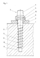
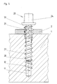
- a rail not shown, in particular a railroad rail, is fastened in a known manner by means of a ribbed plate 2 on a wooden sleeper 1.
- the ribbed plate 2 is fastened by means of four sleeper screws 3 screwed into the sleeper 1.
- Each threshold screw 3 has a head 4 with a molded collar 5, an adjoining threadless upper shaft part 6 and a lower lower shaft part 8 carrying a coarse thread 7.
- the diameter of the threadless shaft part 6 is equal to the outer diameter of the Coarse thread 7 provided shaft portion 8 measured over the thread tips. This outer diameter corresponds essentially to the diameter of the exit hole 9 in the fin plate 2.
- a spring ring 10 is arranged between the fin plate 2 and the collar 5.
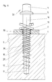
- the diameter of the upper, unthreaded shaft 16 is equal to the diameter of the unthreaded shaft 6 of the old sleeper screw 3.
- the difference between the new sleeper screw 14 and the design of the lower shaft 18 is that the shaft 18 has a two-start thread 17, 19, the slope of which is equal to the slope of the coarse thread 7 of the old screw 3.
- a thread 17 has a wider tooth shape than the coarse thread 7 of the old sleeper screw 3.
- the outside diameter of this thread 17 measured over the flattened tips is not larger than that of the coarse thread 7 of the old sleeper screw 3.
- this thread 17 extends to the shaft tip.
- the thread 19 formed between this thread 17, however, does not extend to the tip of the shaft, but is set back by one to three threads.
- the outside diameter of this thread 19, measured over the tips, is however the same size as the wider thread 17.
- the flank angle of this thread is preferably 34 ° .
- the beginnings of both threads 17.19 do not begin in their full strength, but gradually increase.
- the section of the shaft 18 which starts from the shaft tip and has only a single thread serves as a guide when screwing in.
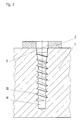
- a tap 20 is screwed into the borehole 11, which has a screw head 24 with the dimensions of the head 4 of the old sleeper screw.
- the head 24 is followed by a shaft section 26 with threading cutters 25 arranged thereon.
- To the Shank section 25 is followed by a shank section 28 with a single-start thread 27.
- This shaft section 28 with the single-start thread 27 is designed like the shaft 8 with its single-start thread 7 of the old sleeper screw 3.
- the diameter of the upper shaft section 26 measured over the tips of the thread cutting edges 25 is larger than that of the through hole 9 in the ribbed plate 2.
- the thread of the thread cutting edge 25 is offset from the thread 27 of the lower shaft 28 in such a way that, if the thread of the thread cutting edge is intended to continue 25 this lies between the thread 27.
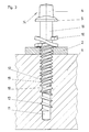
- a new two-start sleeper screw 33 can be screwed into the sleeper 1 according to FIG. 6, as shown in FIG. 6.
- This sleeper screw 33 like the sleeper screw 14 of FIG. 3, has a two-start thread 37, 39 which differs from the two-start thread of the sleeper screw 14 only in that the thread 39 formed with sharp tips has a larger diameter than the other, measured via these tips Has thread 17 with the wider tooth shape.
- This larger thread 39 is assigned to the thread 30 cut into the ribbed plate 2.
- the threshold screw 33 is screwed through the thread 39 which engages in the old thread 12 of the borehole 11.
- the other, pointed thread 37 cuts a new thread into the wood of the sleeper 1. Due to the higher than 37 in the embodiment of Figure 3 formed in this embodiment of Figure 6, even with strong weathering of the wood in the through holes, a good anchorage of the new sleeper screw 33 is obtained. For cutting the thread no machine is required since the tap 20 can be screwed in using the usual screwing tools.
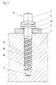
- FIG. 7 differs from that of FIG. 6 primarily in that a single threshold screw 133 is used as the new threshold screw.
- a thread 130 is cut into the fin plate 2, as in the exemplary embodiment in FIG. 5, which, in contrast to that in FIG. 6, is not half a thread turn compared to the old thread cut in the sleeper 1 12 is offset, but merges into this.
- the core diameter of the upper shaft part 106 and the middle shaft part 108 could be practically the same as the inner diameter of the through hole 9 in the ribbed plate 2, but for manufacturing reasons it is smaller, but larger than that of the old sleeper screw.
- a sleeper screw can be screwed in, which has a volume which is substantially larger than that of the exemplary embodiment in FIG.
- Another special feature of the new sleeper screw 133 is that the shaft part 106 has a conical section 101 in the non-threaded part directly below the enlarged collar 105 of the head 104, the largest diameter of which is equal to the outside diameter of the thread 137. This ensures that the spring ring 100 can be pushed over the thread 137 and is centered radially by the conical part 101 during assembly.
- the spring ring 100 would sit on the shaft 106 with radial play and would therefore be able to move eccentrically under the collar 105 during assembly as desired.
- the last A special feature of the sleeper screw 133 compared to the sleeper screw according to FIG. 6 is that the shaft part 108 is longer. Since the boreholes 11 in the sleepers 1 regularly have a depth exceeding the length of the shaft of the sleeper screw for the initial assembly, the new longer sleeper screw 133 also utilizes the lower area not previously used. This measure also contributes to a better hold of the threshold screw 133 in the threshold 1.
Landscapes
- Engineering & Computer Science (AREA)
- Mechanical Engineering (AREA)
- Architecture (AREA)
- Civil Engineering (AREA)
- Structural Engineering (AREA)
- Machines For Laying And Maintaining Railways (AREA)
- Hand Tools For Fitting Together And Separating, Or Other Hand Tools (AREA)
- Connection Of Plates (AREA)
Priority Applications (1)
| Application Number | Priority Date | Filing Date | Title |
|---|---|---|---|
| AT90101041T ATE94925T1 (de) | 1989-03-25 | 1990-01-19 | Verfahren zum reparieren von befestigungen fuer auf holzschwellen verlegte eisenbahnschienen und schwellenschraube fuer reparaturzwecke. |
Applications Claiming Priority (2)
| Application Number | Priority Date | Filing Date | Title |
|---|---|---|---|
| DE3909826 | 1989-03-25 | ||
| DE3909826A DE3909826A1 (de) | 1989-03-25 | 1989-03-25 | Schwellenschraube zum reparieren von befestigungen von schienen auf holzschwellen und verwendung der schwellenschraube fuer reparaturzwecke |
Publications (3)
| Publication Number | Publication Date |
|---|---|
| EP0389746A2 EP0389746A2 (de) | 1990-10-03 |
| EP0389746A3 EP0389746A3 (de) | 1991-06-12 |
| EP0389746B1 true EP0389746B1 (de) | 1993-09-22 |
Family
ID=6377182
Family Applications (1)
| Application Number | Title | Priority Date | Filing Date |
|---|---|---|---|
| EP90101041A Expired - Lifetime EP0389746B1 (de) | 1989-03-25 | 1990-01-19 | Verfahren zum Reparieren von Befestigungen für auf Holzschwellen verlegte Eisenbahnschienen und Schwellenschraube für Reparaturzwecke |
Country Status (4)
| Country | Link |
|---|---|
| EP (1) | EP0389746B1 (OSRAM) |
| AT (1) | ATE94925T1 (OSRAM) |
| DE (3) | DE3909826A1 (OSRAM) |
| ES (1) | ES2059838T3 (OSRAM) |
Cited By (1)
| Publication number | Priority date | Publication date | Assignee | Title |
|---|---|---|---|---|
| WO2018211196A1 (fr) * | 2017-05-18 | 2018-11-22 | Ateliers Lr Etanco | Dispositif et procede pour reparer une attache de rail |
Families Citing this family (3)
| Publication number | Priority date | Publication date | Assignee | Title |
|---|---|---|---|---|
| GB2330638B (en) * | 1997-10-23 | 2001-09-26 | Pandrol Ltd | Fastening device |
| DE19859696C1 (de) * | 1998-12-23 | 2000-03-30 | Schraubenwerk Zerbst Gmbh | Verankerungsschraube für Schwellen und dgl. |
| DE202005002534U1 (de) † | 2005-02-17 | 2006-06-29 | Fischerwerke Artur Fischer Gmbh & Co. Kg | Dämmstoffhalter |
Family Cites Families (6)
| Publication number | Priority date | Publication date | Assignee | Title |
|---|---|---|---|---|
| US2231771A (en) * | 1938-02-24 | 1941-02-11 | Clarence E Murphy | Tie plate fastener |
| FR1102146A (fr) * | 1954-03-31 | 1955-10-17 | Boulonneries & Ferronneries D | Tirefond indesserrable |
| US3861269A (en) * | 1971-01-04 | 1975-01-21 | Superior Dry Wall Screw Mfg Co | Fastener with improved thread construction |
| DE8304915U1 (de) * | 1983-02-22 | 1985-01-24 | Vossloh-Werke Gmbh, 5980 Werdohl | Spreizduebel zur altschwellensanierung |
| GB8531731D0 (en) * | 1985-12-24 | 1986-02-05 | Multiclip Co Ltd | Securing devices |
| DE3626148A1 (de) * | 1986-08-01 | 1988-02-04 | Ver Schraubenwerke Gmbh | Verfahren zum reparieren von befestigungen von schienen auf holzschwellen sowie bohrwerkzeug zur durchfuehrung des verfahrens und schwellenschraube zur verwendung bei dem verfahren |
-
1989
- 1989-03-25 DE DE3909826A patent/DE3909826A1/de active Granted
-
1990
- 1990-01-19 EP EP90101041A patent/EP0389746B1/de not_active Expired - Lifetime
- 1990-01-19 ES ES90101041T patent/ES2059838T3/es not_active Expired - Lifetime
- 1990-01-19 AT AT90101041T patent/ATE94925T1/de not_active IP Right Cessation
- 1990-01-19 DE DE90101041T patent/DE59002789D1/de not_active Expired - Lifetime
- 1990-02-03 DE DE9001195U patent/DE9001195U1/de not_active Expired - Lifetime
Cited By (2)
| Publication number | Priority date | Publication date | Assignee | Title |
|---|---|---|---|---|
| WO2018211196A1 (fr) * | 2017-05-18 | 2018-11-22 | Ateliers Lr Etanco | Dispositif et procede pour reparer une attache de rail |
| FR3066507A1 (fr) * | 2017-05-18 | 2018-11-23 | Ateliers Lr Etanco | Dispositif et procede associe pour reparer une attache de rail. |
Also Published As
| Publication number | Publication date |
|---|---|
| ATE94925T1 (de) | 1993-10-15 |
| DE3909826A1 (de) | 1990-10-04 |
| DE9001195U1 (de) | 1990-07-26 |
| DE59002789D1 (de) | 1993-10-28 |
| EP0389746A2 (de) | 1990-10-03 |
| ES2059838T3 (es) | 1994-11-16 |
| EP0389746A3 (de) | 1991-06-12 |
| DE3909826C2 (OSRAM) | 1991-04-18 |
Similar Documents
| Publication | Publication Date | Title |
|---|---|---|
| DE2805071C2 (de) | Schraube | |
| EP1015774B1 (de) | Befestigung von Latten aus Holz auf einem u.a. aus Holz bestehenden Dach- oder Wandunterbau | |
| EP0102605A1 (de) | Holzschraube | |
| EP0292742B1 (de) | Distanzschraube | |
| DE19615191A1 (de) | Schraube zur Befestigung von Metall- und/oder Kunststoffprofilen oder -platten auf einem Unterbau | |
| DE8512712U1 (de) | Schraube | |
| EP1235988B1 (de) | Schraube zur abstandsbefestigung von abdeckplatten oder schienen an einem unterbau | |
| EP1215404A1 (de) | Befestigungsvorrichtung für ein an einer Platte zu befestigendes Bauteil | |
| DE3715420A1 (de) | Distanzschraube | |
| AT409988B (de) | Verfahren zum befestigen von holzkonstruktionsteilen vor einer betonwand oder mauer | |
| EP0988427B1 (de) | Verbindungselement zum verbinden von wenigstens zwei holzbauteilen und einer knotenplatte | |
| DE8606197U1 (de) | Selbstschneidende Schraube | |
| EP0389746B1 (de) | Verfahren zum Reparieren von Befestigungen für auf Holzschwellen verlegte Eisenbahnschienen und Schwellenschraube für Reparaturzwecke | |
| DE4222248C2 (de) | Verbindungseinsatz | |
| DE3827773C2 (de) | Befestigungsvorrichtung für Schienen | |
| DE19755953C2 (de) | Schraube zur Abstandsbefestigung von Abdeckplatten oder Schienen an einem Unterbau | |
| DE20121563U1 (de) | Schraube zum Befestigen einer Schalungsplatte | |
| EP0532990A2 (de) | Gewindefurchende Schraube sowie Verfahren zum Herstellen derselben und Walzbacken zur Durchführung des Verfahrens | |
| DE3626148A1 (de) | Verfahren zum reparieren von befestigungen von schienen auf holzschwellen sowie bohrwerkzeug zur durchfuehrung des verfahrens und schwellenschraube zur verwendung bei dem verfahren | |
| DE3844113A1 (de) | Befestigungselement | |
| EP0527999B1 (de) | Schraube zum eindrehen in sacklöcher geringer tiefe | |
| DE2038885A1 (de) | Schraubnagel | |
| EP2895751B1 (de) | Schraube und ihre verwendung | |
| EP0518079B1 (de) | Osteosyntheseimplantat | |
| WO1999031395A1 (de) | Schraube zur abstandsbefestigung von abdeckplatten oder schienen an einem unterbau |
Legal Events
| Date | Code | Title | Description |
|---|---|---|---|
| PUAI | Public reference made under article 153(3) epc to a published international application that has entered the european phase |
Free format text: ORIGINAL CODE: 0009012 |
|
| AK | Designated contracting states |
Kind code of ref document: A2 Designated state(s): AT BE CH DE DK ES FR GB GR IT LI LU NL SE |
|
| PUAL | Search report despatched |
Free format text: ORIGINAL CODE: 0009013 |
|
| AK | Designated contracting states |
Kind code of ref document: A3 Designated state(s): AT BE CH DE DK ES FR GB GR IT LI LU NL SE |
|
| 17P | Request for examination filed |
Effective date: 19910705 |
|
| 17Q | First examination report despatched |
Effective date: 19920202 |
|
| GRAA | (expected) grant |
Free format text: ORIGINAL CODE: 0009210 |
|
| AK | Designated contracting states |
Kind code of ref document: B1 Designated state(s): AT BE CH DE DK ES FR GB GR IT LI LU NL SE |
|
| PG25 | Lapsed in a contracting state [announced via postgrant information from national office to epo] |
Ref country code: DK Effective date: 19930922 |
|
| REF | Corresponds to: |
Ref document number: 94925 Country of ref document: AT Date of ref document: 19931015 Kind code of ref document: T |
|
| REF | Corresponds to: |
Ref document number: 59002789 Country of ref document: DE Date of ref document: 19931028 |
|
| ITF | It: translation for a ep patent filed | ||
| GBT | Gb: translation of ep patent filed (gb section 77(6)(a)/1977) |
Effective date: 19931208 |
|
| RAP2 | Party data changed (patent owner data changed or rights of a patent transferred) |
Owner name: VOSSLOH-WERKE GMBH |
|
| REG | Reference to a national code |
Ref country code: CH Ref legal event code: PUE Owner name: VOSSLOH-WERKE GMBH |
|
| EPTA | Lu: last paid annual fee | ||
| ET | Fr: translation filed | ||
| REG | Reference to a national code |
Ref country code: GR Ref legal event code: FG4A Free format text: 3010128 |
|
| REG | Reference to a national code |
Ref country code: GB Ref legal event code: 732E |
|
| NLS | Nl: assignments of ep-patents |
Owner name: VOSSLOH-WERKE GMBH TE WERDOHL, BONDSREPUBLIEK DUIT |
|
| PLBE | No opposition filed within time limit |
Free format text: ORIGINAL CODE: 0009261 |
|
| STAA | Information on the status of an ep patent application or granted ep patent |
Free format text: STATUS: NO OPPOSITION FILED WITHIN TIME LIMIT |
|
| 26N | No opposition filed | ||
| REG | Reference to a national code |
Ref country code: ES Ref legal event code: FG2A Ref document number: 2059838 Country of ref document: ES Kind code of ref document: T3 |
|
| EAL | Se: european patent in force in sweden |
Ref document number: 90101041.3 |
|
| REG | Reference to a national code |
Ref country code: GB Ref legal event code: IF02 |
|
| PGFP | Annual fee paid to national office [announced via postgrant information from national office to epo] |
Ref country code: AT Payment date: 20090128 Year of fee payment: 20 Ref country code: LU Payment date: 20090126 Year of fee payment: 20 Ref country code: ES Payment date: 20090127 Year of fee payment: 20 |
|
| PGFP | Annual fee paid to national office [announced via postgrant information from national office to epo] |
Ref country code: NL Payment date: 20090127 Year of fee payment: 20 Ref country code: DE Payment date: 20090123 Year of fee payment: 20 |
|
| PGFP | Annual fee paid to national office [announced via postgrant information from national office to epo] |
Ref country code: CH Payment date: 20090123 Year of fee payment: 20 Ref country code: GR Payment date: 20081223 Year of fee payment: 20 Ref country code: GB Payment date: 20090123 Year of fee payment: 20 |
|
| PGFP | Annual fee paid to national office [announced via postgrant information from national office to epo] |
Ref country code: BE Payment date: 20090219 Year of fee payment: 20 |
|
| PGFP | Annual fee paid to national office [announced via postgrant information from national office to epo] |
Ref country code: SE Payment date: 20090123 Year of fee payment: 20 Ref country code: IT Payment date: 20090127 Year of fee payment: 20 |
|
| PGFP | Annual fee paid to national office [announced via postgrant information from national office to epo] |
Ref country code: FR Payment date: 20090123 Year of fee payment: 20 |
|
| REG | Reference to a national code |
Ref country code: CH Ref legal event code: PL |
|
| BE20 | Be: patent expired |
Owner name: *VOSSLOH-WERKE G.M.B.H. Effective date: 20100119 |
|
| REG | Reference to a national code |
Ref country code: GB Ref legal event code: PE20 Expiry date: 20100118 |
|
| NLV7 | Nl: ceased due to reaching the maximum lifetime of a patent |
Effective date: 20100119 |
|
| EUG | Se: european patent has lapsed | ||
| REG | Reference to a national code |
Ref country code: ES Ref legal event code: FD2A Effective date: 20100120 |
|
| PG25 | Lapsed in a contracting state [announced via postgrant information from national office to epo] |
Ref country code: ES Free format text: LAPSE BECAUSE OF EXPIRATION OF PROTECTION Effective date: 20100120 |
|
| PG25 | Lapsed in a contracting state [announced via postgrant information from national office to epo] |
Ref country code: GB Free format text: LAPSE BECAUSE OF EXPIRATION OF PROTECTION Effective date: 20100118 |
|
| PG25 | Lapsed in a contracting state [announced via postgrant information from national office to epo] |
Ref country code: NL Free format text: LAPSE BECAUSE OF EXPIRATION OF PROTECTION Effective date: 20100119 |
|
| PG25 | Lapsed in a contracting state [announced via postgrant information from national office to epo] |
Ref country code: DE Free format text: LAPSE BECAUSE OF EXPIRATION OF PROTECTION Effective date: 20100119 |