EP0389746B1 - Process for repairing railway fastenings on wooden sleepers and sleeper screw for purpose of repair - Google Patents
Process for repairing railway fastenings on wooden sleepers and sleeper screw for purpose of repair Download PDFInfo
- Publication number
- EP0389746B1 EP0389746B1 EP90101041A EP90101041A EP0389746B1 EP 0389746 B1 EP0389746 B1 EP 0389746B1 EP 90101041 A EP90101041 A EP 90101041A EP 90101041 A EP90101041 A EP 90101041A EP 0389746 B1 EP0389746 B1 EP 0389746B1
- Authority
- EP
- European Patent Office
- Prior art keywords
- thread
- sleeper
- screw
- old
- screws
- Prior art date
- Legal status (The legal status is an assumption and is not a legal conclusion. Google has not performed a legal analysis and makes no representation as to the accuracy of the status listed.)
- Expired - Lifetime
Links
Images

Classifications
-
- E—FIXED CONSTRUCTIONS
- E01—CONSTRUCTION OF ROADS, RAILWAYS, OR BRIDGES
- E01B—PERMANENT WAY; PERMANENT-WAY TOOLS; MACHINES FOR MAKING RAILWAYS OF ALL KINDS
- E01B9/00—Fastening rails on sleepers, or the like
- E01B9/02—Fastening rails, tie-plates, or chairs directly on sleepers or foundations; Means therefor
- E01B9/04—Fastening on wooden or concrete sleepers or on masonry without clamp members
- E01B9/10—Screws or bolts for sleepers
-
- E—FIXED CONSTRUCTIONS
- E01—CONSTRUCTION OF ROADS, RAILWAYS, OR BRIDGES
- E01B—PERMANENT WAY; PERMANENT-WAY TOOLS; MACHINES FOR MAKING RAILWAYS OF ALL KINDS
- E01B31/00—Working rails, sleepers, baseplates, or the like, in or on the line; Machines, tools, or auxiliary devices specially designed therefor
- E01B31/20—Working or treating non-metal sleepers in or on the line, e.g. marking, creosoting
- E01B31/24—Forming, treating, reconditioning, or cleaning holes in sleepers; Drilling-templates
Definitions
- the invention relates to a method for repairing fastenings for railway tracks laid on wooden sleepers.
- Rib plates are used to fasten rails, in particular railway rails, to wooden sleepers, which are fastened directly to the sleepers using sleeper screws. It is common for spring washers to be arranged between the head of the sleeper screw and the ribbed plate.
- the rails themselves are attached to the ribbed plates by means of clamping elements.
- the repair of such loosened rail fastenings usually consists of removing the ribbed plates after loosening the rail fastener and often even removing the sleepers in order to remove the rotten wood by drilling the holes. A dowel is then inserted into the borehole thus widened so that the ribbed plate can be reattached by means of the usual threshold screws having a wood thread (DE-GM 83 04 915).
- the invention has for its object to provide a method with which the fastening of rails on wooden sleepers without drilling with drills and without inserting dowels, spirals or the like is possible in the boreholes.
- the invention relates to a method for repairing fastenings for railway rails laid on wooden sleepers, which consist of ribbed plates fastened with sleeper screws, in which the old Sleeper screws are replaced by new sleeper screws with more thread volume than the old sleeper screws.
- the solution to the problem in such a method is that internal threads are cut into the through holes of the rib plates and that the new sleeper screws are then screwed in, the thread of which corresponds to the internal thread in the through holes of the rib plate and the shaft end facing the screw head has a threadless section , whose diameter is at most equal to the inside diameter of the non-drilled through holes of the ribbed plate, the threads cut by the old sleeper screws in the drill holes of the sleeper serving as a guide for the tap when cutting the internal threads into the through holes when cutting the internal threads, and the thread pitch of the new ones Sleeper screws are the same as the old sleeper screws.
- the thread cut in the drill holes of the sleeper by the old sleeper screws is used to facilitate screwing in the new sleeper screws or to enable them in the first place.
- the old thread serves as a guide for the tap.
- sleeper screws can be used which have at least one guide section adjoining the shaft tip with the same thread as the old sleeper screws. In this case, the old thread is also used as a guide when screwing in the new sleeper screw.
- sleeper screws can be used, the core diameter of which in the area of the thread is also larger than that of the old sleeper screws. A large shrinkage of the wood in the boreholes can be compensated with such sleeper screws.
- the solution according to the invention can also be implemented with a two-start thread.
- the outer diameter of the second thread is equal to the diameter of the through holes. If, in this embodiment, a thread is provided in the guide section which is the same as the thread of the old sleeper screw, then this thread should pass into the thread of the two-start thread, the outer diameter of which is at most equal to the diameter of the through holes not drilled out.
- the dimensioning of the thread in the guide section does not have to correspond to that of the old sleeper screw, but can have a wider tooth shape in order to bring as much thread volume into the drill hole of the sleeper screw and thus to give the sleeper screw a better hold.
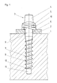
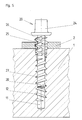
- a rail not shown, in particular a railroad rail, is fastened in a known manner by means of a ribbed plate 2 on a wooden sleeper 1.
- the ribbed plate 2 is fastened by means of four sleeper screws 3 screwed into the sleeper 1.
- Each threshold screw 3 has a head 4 with a molded collar 5, an adjoining threadless upper shaft part 6 and a lower lower shaft part 8 carrying a coarse thread 7.
- the diameter of the threadless shaft part 6 is equal to the outer diameter of the Coarse thread 7 provided shaft portion 8 measured over the thread tips. This outer diameter corresponds essentially to the diameter of the exit hole 9 in the fin plate 2.
- a spring ring 10 is arranged between the fin plate 2 and the collar 5.
- the diameter of the upper, unthreaded shaft 16 is equal to the diameter of the unthreaded shaft 6 of the old sleeper screw 3.
- the difference between the new sleeper screw 14 and the design of the lower shaft 18 is that the shaft 18 has a two-start thread 17, 19, the slope of which is equal to the slope of the coarse thread 7 of the old screw 3.
- a thread 17 has a wider tooth shape than the coarse thread 7 of the old sleeper screw 3.
- the outside diameter of this thread 17 measured over the flattened tips is not larger than that of the coarse thread 7 of the old sleeper screw 3.
- this thread 17 extends to the shaft tip.
- the thread 19 formed between this thread 17, however, does not extend to the tip of the shaft, but is set back by one to three threads.
- the outside diameter of this thread 19, measured over the tips, is however the same size as the wider thread 17.
- the flank angle of this thread is preferably 34 ° .
- the beginnings of both threads 17.19 do not begin in their full strength, but gradually increase.
- the section of the shaft 18 which starts from the shaft tip and has only a single thread serves as a guide when screwing in.
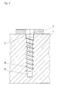
- a tap 20 is screwed into the borehole 11, which has a screw head 24 with the dimensions of the head 4 of the old sleeper screw.
- the head 24 is followed by a shaft section 26 with threading cutters 25 arranged thereon.
- To the Shank section 25 is followed by a shank section 28 with a single-start thread 27.
- This shaft section 28 with the single-start thread 27 is designed like the shaft 8 with its single-start thread 7 of the old sleeper screw 3.
- the diameter of the upper shaft section 26 measured over the tips of the thread cutting edges 25 is larger than that of the through hole 9 in the ribbed plate 2.
- the thread of the thread cutting edge 25 is offset from the thread 27 of the lower shaft 28 in such a way that, if the thread of the thread cutting edge is intended to continue 25 this lies between the thread 27.
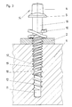
- a new two-start sleeper screw 33 can be screwed into the sleeper 1 according to FIG. 6, as shown in FIG. 6.
- This sleeper screw 33 like the sleeper screw 14 of FIG. 3, has a two-start thread 37, 39 which differs from the two-start thread of the sleeper screw 14 only in that the thread 39 formed with sharp tips has a larger diameter than the other, measured via these tips Has thread 17 with the wider tooth shape.
- This larger thread 39 is assigned to the thread 30 cut into the ribbed plate 2.
- the threshold screw 33 is screwed through the thread 39 which engages in the old thread 12 of the borehole 11.
- the other, pointed thread 37 cuts a new thread into the wood of the sleeper 1. Due to the higher than 37 in the embodiment of Figure 3 formed in this embodiment of Figure 6, even with strong weathering of the wood in the through holes, a good anchorage of the new sleeper screw 33 is obtained. For cutting the thread no machine is required since the tap 20 can be screwed in using the usual screwing tools.
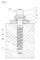
- FIG. 7 differs from that of FIG. 6 primarily in that a single threshold screw 133 is used as the new threshold screw.
- a thread 130 is cut into the fin plate 2, as in the exemplary embodiment in FIG. 5, which, in contrast to that in FIG. 6, is not half a thread turn compared to the old thread cut in the sleeper 1 12 is offset, but merges into this.
- the core diameter of the upper shaft part 106 and the middle shaft part 108 could be practically the same as the inner diameter of the through hole 9 in the ribbed plate 2, but for manufacturing reasons it is smaller, but larger than that of the old sleeper screw.
- a sleeper screw can be screwed in, which has a volume which is substantially larger than that of the exemplary embodiment in FIG.
- Another special feature of the new sleeper screw 133 is that the shaft part 106 has a conical section 101 in the non-threaded part directly below the enlarged collar 105 of the head 104, the largest diameter of which is equal to the outside diameter of the thread 137. This ensures that the spring ring 100 can be pushed over the thread 137 and is centered radially by the conical part 101 during assembly.
- the spring ring 100 would sit on the shaft 106 with radial play and would therefore be able to move eccentrically under the collar 105 during assembly as desired.
- the last A special feature of the sleeper screw 133 compared to the sleeper screw according to FIG. 6 is that the shaft part 108 is longer. Since the boreholes 11 in the sleepers 1 regularly have a depth exceeding the length of the shaft of the sleeper screw for the initial assembly, the new longer sleeper screw 133 also utilizes the lower area not previously used. This measure also contributes to a better hold of the threshold screw 133 in the threshold 1.
Abstract
Description
Die Erfindung betrifft ein Verfahren zum Reparieren von Befestigungen für auf Holzschwellen verlegte Eisenbahnschienen. Zum Befestigen von Schienen, insbesondere Eisenbahnschienen auf Holzschwellen, werden Rippenplatten eingesetzt, die mittels Schwellenschrauben unmittelbar auf den Schwellen befestigt werden. Dabei ist es üblich, daß zwischen dem Kopf der Schwellenschraube und der Rippenplatte Federringe angeordnet werden. Die Schienen selbst sind mittels Klemmelementen an den Rippenplatten befestigt. Infolge der beim Befahren der Schienen auftretenden Wechselbelastung aber auch des Einflusses der Witterung lockern sich die Schwellenschrauben in den Holzschwellen im Laufe der Jahre. Durch in das Bohrloch eindringendes Regenwasser kommt es darüber hinaus zu einem natürlichen Verrotten des Holzes im Bereich des Bohrloches.The invention relates to a method for repairing fastenings for railway tracks laid on wooden sleepers. Rib plates are used to fasten rails, in particular railway rails, to wooden sleepers, which are fastened directly to the sleepers using sleeper screws. It is common for spring washers to be arranged between the head of the sleeper screw and the ribbed plate. The rails themselves are attached to the ribbed plates by means of clamping elements. As a result of the alternating load that occurs when the rails are driven, but also the influence of the weather, the sleeper screws in the wooden sleepers become loose over the years. Rainwater entering the borehole also causes the wood to rot naturally in the area of the borehole.
Die Reparatur derart gelockerter Schienenbefestigungen besteht in der Regel darin, daß nach Lösen der Schienenbefestigung die Rippenplatten ausgebaut und häufig sogar die Schwellen ausgebaut werden, um durch Aufbohren der Bohrlöcher das verrottete Holz zu entfernen. In das so aufgeweitete Bohrloch wird dann ein Dübel eingesetzt, so daß mittels der üblichen, ein Holzgewinde aufweisenden Schwellenschrauben die Rippenplatte wieder befestigt werden kann (DE-GM 83 04 915).The repair of such loosened rail fastenings usually consists of removing the ribbed plates after loosening the rail fastener and often even removing the sleepers in order to remove the rotten wood by drilling the holes. A dowel is then inserted into the borehole thus widened so that the ribbed plate can be reattached by means of the usual threshold screws having a wood thread (DE-GM 83 04 915).
Dieser Aufwand wird bei einem bekannten Verfahren dadurch vermindert, daß das Aufbohren der alten Bohrlöcher für die Schwellenschrauben im eingebauten Zustand der Holzschwellen erfolgt und in das aufgebohrte Bohrloch eine Schwellenschraube mit selbstschneidendem Gewinde eingeschraubt wird, deren Schaft gegenüber der alten Schwellenschraube ein feingängigeres Gewinde und einen solchen Durchmesser hat, daß er mit radialem Preßsitz im Bohrloch verankert ist. Sofern zwischen den Schienen und den Holzschwellen Rippenplatten eingesetzt sind, werden diese in einem Arbeitsgang mit dem Bohrloch aufgebohrt. Zwar erfüllt ein solches Verfahren alle Anforderungen hinsichtlich eines geringen Aufwandes und eines auf lange Dauer wieder festen Sitzes der Schraube, doch hat es sich in der Praxis deshalb nicht durchsetzen können, weil zum Aufbohren des Bohrloches in der Schwelle eine Bohrmaschine für den Antrieb des Bohrwerkzeuges notwendig ist. Solche Bohrmaschinen stehen der Reparaturkolonne aber nicht ohne weiteres zur Verfügung. Hinzu kommt, daß das Aufbohren der Rippenplatte unerwünscht ist, weil sie dann nicht mehr für die Neubestückung einer Befestigung verwendbar ist (DE 36 26 148 A1).This effort is reduced in a known method in that the drilling of the old drill holes for the sleeper screws takes place in the installed state of the wooden sleepers and a sleeper screw with a self-tapping thread is screwed into the drilled borehole, the shaft of which compared to the old sleeper screw has a finer thread and such Diameter has that it is anchored in the borehole with a radial press fit. If ribbed plates are inserted between the rails and the wooden sleepers, they are drilled out with the borehole in one operation. Although such a method fulfills all requirements with regard to little effort and a long-term secure fit of the screw, it has not been able to prevail in practice because a drill for driving the drilling tool is necessary to drill the drill hole in the sleeper is. Such drilling machines are not readily available to the repair column. In addition, the drilling of the ribbed plate is undesirable because it can then no longer be used for refitting an attachment (DE 36 26 148 A1).
Bei einem ganz anderen Reparaturverfahren wird an dem Bohrloch für die Schwellenschrauben selbst nichts verändert, sondern nach Entfernen der Schwellenschraube wird in das Bohrloch eine metallische Spirale eingeschraubt, die dann beim Einschrauben der alten Schwellenschraube gespreizt und in das Holz eindringt, um der Schwellenschraube wieder Halt zu geben (EP 0 228 269).In a completely different repair procedure, nothing is changed on the drill hole for the sleeper screw itself, but after removing the sleeper screw, a metallic spiral is screwed into the drill hole, which then spreads when the old sleeper screw is screwed in and penetrates into the wood in order to hold the sleeper screw again give (EP 0 228 269).
Schließlich ist es bekannt, in das alte Bohrloch mit den von der alten Schwellenschraube eingeschnittenen Gewindegängen eine neue Schwellenschraube einzusetzen, die ein zweigängiges Gewinde aufweist, von denen das eine Gewinde über die Spitzen der Gewindegänge gemessen einen größeren Außendurchmesser als das andere Gewinde hat. Der Außendurchmesser des größeren Gewindes ist gleich dem Durchmesser des sich am Schraubenkopf anschließenden gewindelosen Abschnittes, auf dem der zwischen der Rippenplatte und dem Schraubenkopf anzuordnende Federring sitzt. Da das zweigängige Gewinde im Vergleich zu einem eingängigen Gewinde ein größeres Gewindevolumen hat, findet eine solche Schwellenschraube im Bohrloch der Schwelle trotz gewisser Verrottung des Holzes Halt. Wegen der Zweigängigkeit des Gewindes ist das Einschrauben nicht leicht (FR-PS 11 02 146).Finally, it is known to insert a new sleeper screw into the old borehole with the threads cut by the old sleeper screw, which has a two-start thread, one of which has a larger outer diameter than the other thread measured over the tips of the threads. The outer diameter of the larger thread is equal to the diameter of the threadless section adjoining the screw head, on which the spring ring to be arranged between the ribbed plate and the screw head sits. Since the double-start thread has a larger thread volume than a single-start thread, such a sleeper screw finds a hold in the drill hole of the sleeper despite certain rotting of the wood. Screwing in is not easy due to the thread's two threads (FR-
Der Erfindung liegt die Aufgabe zugrunde, ein Verfahren anzugeben, mit denen die Befestigungen von Schienen auf Holzschwellen ohne Aufbohren mit Bohrmaschinen und ohne Einsetzen von Dübel, Spiralen oder dergleichen in die Bohrlöcher möglich ist.The invention has for its object to provide a method with which the fastening of rails on wooden sleepers without drilling with drills and without inserting dowels, spirals or the like is possible in the boreholes.
Die Erfindung geht aus von einem Verfahren zum Reparieren von Befestigungen für auf Holzschwellen verlegte Eisenbahnschienen, die aus mit Schwellenschrauben befestigten Rippenplatten bestehen, bei dem die alten Schwellenschrauben durch neue Schwellenschrauben mit mehr Gewindevolumen als die alten Schwellenschrauben ersetzt werden.The invention relates to a method for repairing fastenings for railway rails laid on wooden sleepers, which consist of ribbed plates fastened with sleeper screws, in which the old Sleeper screws are replaced by new sleeper screws with more thread volume than the old sleeper screws.
Die Lösung der Aufgabe besteht bei einem solchen Verfahren darin, daß in die Durchgangslöcher der Rippenplatten Innengewinde eingeschnitten werden und daß anschließend die neuen Schwellenschrauben eingeschraubt werden, deren Gewinde dem Innengewinde in den Durchgangslöchern der Rippenplatte entspricht und die am dem Schraubenkopf zugewandten Schaftende einen gewindelosen Abschnitt aufweisen, dessen Durchmesser höchstens gleich dem Innendurchmesser der nicht aufgebohrten Durchgangslöcher der Rippenplatte ist, wobei beim Einschneiden der Innengewinde die von den alten Schwellenschrauben in den Bohrlöchern der Schwelle eingeschnittenen Gewinde dem Gewindeschneider beim Einschneiden der Innengewinde in die Durchgangslöcher als Führung dienen und wobei die Gewindesteigung der neuen Schwellenschrauben gleich der der alten Schwellenschrauben ist.The solution to the problem in such a method is that internal threads are cut into the through holes of the rib plates and that the new sleeper screws are then screwed in, the thread of which corresponds to the internal thread in the through holes of the rib plate and the shaft end facing the screw head has a threadless section , whose diameter is at most equal to the inside diameter of the non-drilled through holes of the ribbed plate, the threads cut by the old sleeper screws in the drill holes of the sleeper serving as a guide for the tap when cutting the internal threads into the through holes when cutting the internal threads, and the thread pitch of the new ones Sleeper screws are the same as the old sleeper screws.
Bei diesem Verfahren wird das in den Bohrlöchern der Schwelle von den alten Schwellenschrauben eingeschnittene Gewinde genutzt, um das Einschrauben der neuen Schwellenschrauben zu erleichtern oder überhaupt erst zu ermöglichen. Dabei dient das alte Gewinde dem Gewindeschneider als Führung. Dabei können Schwellenschrauben Verwendung finden, die zumindest einen sich an die Schaftspitze anschließenden Führungsabschnitt mit gleichem Gewinde wie die alten Schwellenschrauben aufweisen. In diesem Fall wird auch beim Einschrauben der neuen Schwellenschraube das alte Gewinde als Führung benutzt. Notwendig ist dies allerdings nicht, denn durch das in die Bohrlöcher der Rippenplatte eingeschnittene Gewinde, das wegen der Verwendung des vom alten Gewinde in den Bohrlöchern der Schwelle geführten Gewindeschneiders auf dieses alte Gewinde ausgerichtet ist, erhalten die neuen Schwellenschrauben eine ausreichende Führung, um auch problemlos in das alte Gewinde in den Bohrlöchern der Schwelle eingeführt werden zu können. Im einfachsten Fall braucht das eingeschnitte Gewinde in der Rippenplatte nicht einmal auf das alte Gewinde in der Schwelle ausgerichtet zu sein, weil dieses eingeschnittene Gewinde der neuen Schwellenschraube eine so gute Führung gibt, daß deren Gewinde in der Lage ist, ein völlig neues Gewinde in die Bohrlöcher der Schwelle einzuschrauben. In jedem Fall ist dies deswegen besonders vorteilhaft, weil diese Lösung die Verwendung von Schwellenschrauben mit größerem Durchmesser erlaubt, ohne daß es dafür erforderlich ist, die Durchgangslöcher aufzubohren. Wegen des in die Durchgangslöcher der Rippenplatte eingeschnittenen Innengewindes lassen sich Schwellenschrauben verwenden, deren Kerndurchmesser im Bereich des Gewindes ebenfalls größer als derjenige der alten Schwellenschrauben ist. Mit solchen Schwellenschrauben läßt sich ein großer Schwund des Holzes in den Bohrlöchern ausgleichen.In this method, the thread cut in the drill holes of the sleeper by the old sleeper screws is used to facilitate screwing in the new sleeper screws or to enable them in the first place. The old thread serves as a guide for the tap. Here, sleeper screws can be used which have at least one guide section adjoining the shaft tip with the same thread as the old sleeper screws. In this case, the old thread is also used as a guide when screwing in the new sleeper screw. However, this is not necessary, because the thread cut into the drill holes in the ribbed plate, which is due to the use of the thread from the old thread in the drill holes in the sleeper If the tap is aligned with this old thread, the new sleeper screws are given sufficient guidance so that they can also be easily inserted into the old thread in the drill holes of the sleeper. In the simplest case, the incised thread in the ribbed plate does not even have to be aligned with the old thread in the sleeper, because this incised thread gives the new sleeper screw so good guidance that its thread is able to insert a completely new thread into the Screw the drill holes into the threshold. In any case, this is particularly advantageous because this solution allows the use of sleeper screws with a larger diameter without it being necessary to drill the through holes. Because of the internal thread cut into the through holes of the ribbed plate, sleeper screws can be used, the core diameter of which in the area of the thread is also larger than that of the old sleeper screws. A large shrinkage of the wood in the boreholes can be compensated with such sleeper screws.
Die erfindungsgemäße Lösung läßt sich auch bei einem zweigängigen Gewinde verwirklichen. In diesem Fall ist der Außendurchmesser des zweiten Gewindes gleich dem Durchmesser der Durchgangslöcher. Sofern bei dieser Ausgestaltung im Führungsabschnitt ein Gewinde vorgesehen ist, das gleich dem Gewinde der alten Schwellenschraube ist, dann sollte dieses Gewinde in das Gewinde des zweigängigen Gewindes übergehen, dessen Außendurchmesser höchstens gleich dem Durchmesser der nicht aufgebohrten Durchgangslöcher ist.The solution according to the invention can also be implemented with a two-start thread. In this case, the outer diameter of the second thread is equal to the diameter of the through holes. If, in this embodiment, a thread is provided in the guide section which is the same as the thread of the old sleeper screw, then this thread should pass into the thread of the two-start thread, the outer diameter of which is at most equal to the diameter of the through holes not drilled out.
Es versteht sich, daß bis auf die Gewindesteigung die Dimensionierung des Gewindes im Führungsabschnitt und bei einem zweigängigen Gewinde das sich daran anschließende Gewinde nicht dem der alten Schwellenschraube entsprechen muß, sondern eine breitere Zahnform haben kann, um möglichst viel Gewindevolumen in das Bohrloch der Schwellenschraube hineinzubringen und damit der Schwellenschraube einen bessseren Halt zu geben.It goes without saying that, apart from the thread pitch, the dimensioning of the thread in the guide section and, in the case of a two-start thread, the dimensioning that follows The thread does not have to correspond to that of the old sleeper screw, but can have a wider tooth shape in order to bring as much thread volume into the drill hole of the sleeper screw and thus to give the sleeper screw a better hold.
Im folgenden wird die Erfindung anhand einer zwei Ausführungsbeispiele darstellenden Zeichnung näher erläutert, wobei die eigentliche Erfindung lediglich in den Fig. 5-7 dargestellt ist. Im einzelnen zeigen:
- Fig. 1
- eine Schwelle mit einer darauf angeordneten Rippenplatte und einer eingeschraubten, locker sitzenden Schwellenschraube im Axialschnitt,
- Fig. 2
- die Schwelle mit Rippenplatte gemäß
Figur 1 ohne Schwellenschraube im Axialschnitt, - Fig. 3
- die Schwelle mit Rippenplatte gemäß
Figur 1 und einer neuen teilweise eingeschraubten Schwellenschraube im Axialschnitt, - Fig. 4
- die Schwelle mit Rippenplatte und vollständig eingeschraubter Schwellenschraube gemäß
Figur 3 im Axialschnitt, - Fig. 5
- die Schwelle mit Rippenplatte gemäß
Figur 1 und einem eingeschraubten Gewindeschneider im Axialschnitt, - Fig. 6
- die Schwelle mit Rippenplatte gemäß
Figur 5 und einer zum Teil eingeschraubten neuen Schwellenschraube im Axialschnitt,
und - Fig. 7
- die Schwelle mit Rippenplatte gemäß
Figur 1 und einer zum Teil eingeschraubten neuen Schwellenschraube im Axialschnitt in einer zuFigur 6 abgewandelten Ausführung.
- Fig. 1
- a sleeper with a rib plate arranged thereon and a screwed-in, loosely fitting sleeper screw in axial section,
- Fig. 2
- the sleeper with ribbed plate according to FIG. 1 without sleeper screw in axial section,
- Fig. 3
- the threshold with ribbed plate according to Figure 1 and a new partially screwed threshold screw in axial section,
- Fig. 4
- the threshold with ribbed plate and fully screwed-in threshold screw according to FIG. 3 in axial section,
- Fig. 5
- the threshold with ribbed plate according to Figure 1 and a screwed tap in axial section,
- Fig. 6
- the sleeper with ribbed plate according to FIG. 5 and a partially screwed-in new sleeper screw in axial section,
and - Fig. 7
- the threshold with a ribbed plate according to FIG. 1 and a partially screwed-in new threshold screw in axial section in a variant of FIG. 6.
Gemäß Figur 1 ist auf einer Holzschwelle 1 eine nicht dargestellte Schiene, insbesondere Eisenbahnschiene, in bekannter Weise mittels einer Rippenplatte 2 befestigt. Die Rippenplatte 2 ist mittels vier in die Schwelle 1 eingeschraubter Schwellenschrauben 3 befestigt. Jede Schwellenschraube 3 weist einen Kopf 4 mit angeformten Bund 5, einen sich hieran anschließenden gewindelosen oberen Schaftteil 6 und einen unteren ein Grobgewinde 7 tragenden unteren Schaftteil 8 auf. Der Durchmesser des gewindelosen Schaftteils 6 ist gleich dem Außendurchmesser des mit dem Grobgewinde 7 versehenen Schaftteils 8 über die Gewindespitzen gemessen. Dieser Außendurchmesser entspricht im wesentlichen dem Durchmesser des Ausgangsloches 9 in der Rippenplatte 2. Zwischen der Rippenplatte 2 und dem Bund 5 ist ein Federring 10 angeordnet.According to FIG. 1, a rail, not shown, in particular a railroad rail, is fastened in a known manner by means of a
Nach längerem Gebrauch lockert sich der feste Sitz des Schaftes 8 in dem im Bohrloch 11 der Holzschwelle 1 durch das Grobgewinde 7 eingeschnittene Gewinde 12 infolge von Verwitterung des Holzes. In Figur 1 ist dies zeichnerisch angedeutet. Um wieder zu einem festen Sitz der Schwellenschraube zu kommen, wird die alte Schwellenschraube 3 entfernt und durch eine neue Schwellenschraube 14 gemäß Figur 3 ersetzt.After prolonged use, the firm fit of the
Bei dieser neuen Schwellenschraube 14 ist der Durchmesser des oberen, gewindelosen Schaftes 16 gleich dem Durchmesser des gewindelosen Schaftes 6 der alten Schwellenschraube 3. Unterschiedlich ist bei der neuen Schwellenschraube 14 die Ausbildung des unteren Schaftes 18. Der Schaft 18 trägt nämlich ein zweigängiges Gewinde 17,19, dessen Steigung aber gleich der Steigung des Grobgewindes 7 der alten Schraube 3 ist. Von den beiden Gewinden 17,19 hat ein Gewinde 17 eine breitere Zahnform als das Grobgewinde 7 der alten Schwellenschraube 3. Der Außendurchmesser dieses Gewindes 17 über die abgeflachten Spitzen gemessen ist aber nicht größer als beim Grobgewinde 7 der alten Schwellenschraube 3. Wie bei der alten Schwellenschraube 3 erstreckt sich dieses Gewinde 17 bis zur Schaftspitze. Das zwischen diesem Gewinde 17 ausgebildete Gewinde 19 erstreckt sich dagegen nicht bis zur Schaftspitze, sondern ist um ein bis drei Gewindegänge zurückversetzt. Der Außendurchmesser dieses Gewindes 19, über die Spitzen gemessen, ist aber gleich groß wie das breitere Gewinde 17. Der Flankenwinkel dieses Gewindes beträgt bevorzugt 34°. Die Anfänge beider Gewinde 17,19 beginnen nicht in ihrer vollen Stärke, sondern nehmen allmählich zu. Der Abschnitt des Schaftes 18, der von der Schaftspitze ausgeht und nur ein eingängiges Gewinde trägt, dient beim Einschrauben als Führung.In the case of this
Wird nun eine solche neue Schwellenschraube 14 in die Schwelle 1 eingeschraubt, dann wird die Schwellenschraube 14 mit ihrer zunächst nur eingängigen Schaftspitze in den alten eingeschnittenen Gewindegängen 12 der Schwelle 1 geführt.If such a
Auch wenn diese verwittert sind, reichen sie für die erforderliche Führung der Schwellenschraube 14 voll aus. Beim weiteren Einschrauben kommen die voll ausgebildeten Bereiche des Gewindes 17 zum Tragen, das die Fäulnisverluste im Holz ausgleicht. Zusätzlich kommt dann auch das dazwischen liegende Gewinde 19 in dem noch annähernd voll vorhandenen Holz zwischen den alten Gewindegängen zur Wirkung, so daß nach vollständigem Einschrauben der Schwellenschraube 14 diese fest in der Schwelle 1 verankert ist.Even if these are weathered, they are sufficient for the required guidance of the
Sofern die Verwitterung des Holzes in der Schwelle 1 weit fortgeschritten ist, so daß sich allein mit einem doppelgängigen Gewinde, dessen Außendurchmesser über die Spitze gemessen aber nicht größer als bei der alten Schwellenschraube ist, keine feste Verankerung in der Schwelle mehr erreichen läßt, dann erfolgt die Reparatur erfindungsgemäß nach dem Ausführungsbeispiel der Figuren 5 und 6.If the weathering of the wood in
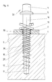
Gemäß Figur 5 wird in das Bohrloch 11 ein Gewindeschneider 20 eingeschraubt, der einen Schraubkopf 24 mit den Abmessungen des Kopfes 4 der alten Schwellenschraube aufweist. An den Kopf 24 schließt sich ein Schaftabschnitt 26 mit darauf angeordneten Gewindeschneiden 25 an. An den Schaftabschnitt 25 schließt sich ein Schaftabschnitt 28 mit einem eingängigen Gewinde 27 an. Dieser Schaftabschnitt 28 mit dem eingängigen Gewinde 27 ist gleich dem Schaft 8 mit seinem eingängigen Gewinde 7 der alten Schwellenschraube 3 ausgebildet. Der Durchmesser des oberen Schaftabschnittes 26 über die Spitzen der Gewindeschneiden 25 gemessen ist größer als der des Durchgangsloches 9 in der Rippenplatte 2. Das Gewinde der Gewindeschneide 25 ist zu dem Gewinde 27 des unteren Schaftes 28 derart versetzt, daß bei gedachter Fortsetzung des Gewindes der Gewindeschneide 25 dieses zwischen dem Gewinde 27 liegt.According to FIG. 5, a
Nachdem mit dem Gewindeschneider 20 ein Gewinde 30 in das Durchgangsloch 9 der Rippenplatte 2 eingeschnitten ist, kann eine neue zweigängige Schwellenschraube 33 in die Schwelle 1 gemäß Figur 6 eingeschraubt werden, wie in Figur 6 dargestellt ist. Diese Schwellenschraube 33 weist wie die Schwellenschraube 14 der Figur 3 ein zweigängiges Gewinde 37,39 auf, das sich von dem zweigängigen Gewinde der Schwellenschraube 14 nur darin unterscheidet, daß das mit scharfen Spitzen ausgebildete Gewinde 39 einen über diese Spitzen gemessenen größeren Durchmesser als das andere Gewinde 17 mit der breiteren Zahnform hat. Dieses größere Gewinde 39 ist dem in die Rippenplatte 2 eingeschnittenen Gewinde 30 zugeordnet. Wie beim Ausführungsbeispiel der Figur 3 wird die Schwellenschraube 33 beim Einschrauben durch das Gewinde 39, das in das alte Gewinde 12 des Bohrloches 11 eingreift, geführt. Beim Einschrauben schneidet sich das andere spitz ausgebildete Gewinde 37 ein neues Gewinde in das Holz der Schwelle 1 ein. Durch das höher als beim Ausführungsbeispiel der Figur 3 ausgebildete spitze Gewinde 37 erhält man bei diesem Ausführungsbeispiel der Figur 6 selbst bei starker Verwitterung des Holzes in den Durchgangslöchern noch eine gute Verankerung der neuen Schwellenschraube 33. Für das Einschneiden des Gewindes wird keine Maschine benötigt, da der Gewindeschneider 20 mittels der üblichen Schraubwerkzeuge eingeschraubt werden kann.After a
Das Ausführungsbeispiel der Figur 7 unterscheidet sich von dem der Figur 6 vor allem darin, daß als neue Schwellenschraube eine eingängige Schwellenschraube 133 eingesetzt ist. Um eine solche eingängige Schwellenschraube 133 einsetzen zu können, wird, wie beim Ausführungsbeispiel der Figur 5, in die Rippenplatte 2 ein Gewinde 130 eingeschnitten, das im Unterschied zu dem der Figur 6 nicht um einen halben Gewindegang gegenüber dem in der Schwelle 1 eingeschnittenen alten Gewinde 12 versetzt ist, sondern in dieses übergeht. Wegen des eingängigen Gewindes 137 der Schwellenschraube 133 könnte der Kerndurchmesser des oberen Schafteils 106 und des mittleren Schaftteils 108 praktisch gleich dem Innendurchmesser des Durchgangsloches 9 in der Rippenplatte 2 sein, aus fertigungstechnischen Gründen ist er aber kleiner, jedoch größer als der der alten Schwellenschraube. Wegen des größeren Außendurchmessers des Gewindes 137, aber auch wegen des größeren Kerndurchmessers und Schaftdurchmessers kann eine Schwellenschraube eingeschraubt werden, die ein im Vergleich zu dem Ausführungsbeispiel der Figur 6 wesentlich größeres Volumen hat. Eine weitere Besonderheit der neuen Schwellenschraube 133 besteht darin, daß der Schaftteil 106 im gewindelosen Teil unmittelbar unter dem im Durchmesser vergrößerten Bund 105 des Kopfes 104 einen konischen Abschnitt 101 aufweist, dessen größter Durchmesser gleich dem Außendurchmesser des Gewindes 137 ist. Dadurch wird gewährleistet, daß der Federring 100 über das Gewinde 137 geschoben werden kann und durch den konischen Teil 101 bei der Montage radial fest zentriert wird. Ohne diesen konischen Teil 101 würde der Federring 100 auf dem Schaft 106 mit radialem Spiel sitzen und sich deshalb nach Belieben exzentrisch unter dem Bund 105 bei der Montage versetzen können. Die letzte Besonderheit der Schwellenschraube 133 gegenüber der Schwellenschraube gemäß Figur 6 besteht darin, daß der Schaftteil 108 länger ausgebildet ist. Da die Bohrlöcher 11 in den Schwellen 1 regelmäßig eine die Länge des Schaftes der Schwellenschraube für die Erstbestückung übertreffende Tiefe haben, wird durch die neue längere Schwellenschraube 133 auch der untere bisher nicht genutzte Bereich ausgenutzt. Auch diese Maßnahme trägt zu einem besseren Halt der Schwellenschraube 133 in der Schwelle 1 bei.The embodiment of FIG. 7 differs from that of FIG. 6 primarily in that a
Claims (6)
- Process for repairing fixtures of rails laid on timber sleepers (1), which consist of ribbed plates (2) fixed with rail screws (3, 33, 133), in which the old rail screws (3) are replaced by new rail screws (33, 133) with bigger size of thread than the old rail screws,
characterized in that inside threads (30, 130) are tapped into the through holes (9) of the ribbed plates (2) and afterwards the new rail srews are screwed in (33, 133), of which the thread (37, 137) corresponds to the inside thread (30, 130) in the drill holes (9) of the ribbed plate and which have a section without thread (16) at the spigot end facing the screw head, the diameter of the section without thread being at most equal to the inside diameter of the non bored through holes (9) of the ribbed plate (2), whereby at the tapping of the inside threads (30, 130) the threads (12) tapped by the old rail screws (3) in the drill holes (11) of the sleeper (1) serve to the thread cutter (20) as guidance and whereby the thread pitch of the new rail screws (33, 133) is equal to that of the old rail screws (3). - Process according to claim 1, characterized in that the new rail screws (33, 133) have at least one guiding section with the same thread (39) as the old rail screws, which is adjacent to the shank point.
- Process according to claim 2, characterized in that the thread in the section adjacent to the guiding section is formed as a double thread (37, 39), of which one thread (39) has an outside diameter which is at most equal to the inside diameter of the non bored through holes (9).
- Process according to claim 3, characterized in that the thread (39) in the guiding section blends the thread of the double thread (37, 39), of which the outside diameter is at most equal to the diameter of the non bored through holes (9).
- Process according to claim 2, characterized in that the thread (137) in the guiding section blends the thread (137) in the section adjacent to the guiding section.
- Process according to one of the claims 1 to 5, characterized in that for a new rail screw (14, 33) with a double thread (17, 19, 37, 39) one thread (17, 39) has a larger tooth formation than the thread of the old rail screw (3).
Priority Applications (1)
| Application Number | Priority Date | Filing Date | Title |
|---|---|---|---|
| AT90101041T ATE94925T1 (en) | 1989-03-25 | 1990-01-19 | METHOD OF REPAIRING RAILROAD RAILWAY RAIL FIXINGS AND SLEEPER SCREW FOR REPAIR PURPOSES. |
Applications Claiming Priority (2)
| Application Number | Priority Date | Filing Date | Title |
|---|---|---|---|
| DE3909826A DE3909826A1 (en) | 1989-03-25 | 1989-03-25 | THRESHOLD SCREW FOR REPAIRING FASTENINGS FROM RAILS TO WOODEN SILLS AND USE OF THRESHOLD SCREW FOR REPAIR PURPOSES |
| DE3909826 | 1989-03-25 |
Publications (3)
| Publication Number | Publication Date |
|---|---|
| EP0389746A2 EP0389746A2 (en) | 1990-10-03 |
| EP0389746A3 EP0389746A3 (en) | 1991-06-12 |
| EP0389746B1 true EP0389746B1 (en) | 1993-09-22 |
Family
ID=6377182
Family Applications (1)
| Application Number | Title | Priority Date | Filing Date |
|---|---|---|---|
| EP90101041A Expired - Lifetime EP0389746B1 (en) | 1989-03-25 | 1990-01-19 | Process for repairing railway fastenings on wooden sleepers and sleeper screw for purpose of repair |
Country Status (4)
| Country | Link |
|---|---|
| EP (1) | EP0389746B1 (en) |
| AT (1) | ATE94925T1 (en) |
| DE (3) | DE3909826A1 (en) |
| ES (1) | ES2059838T3 (en) |
Cited By (1)
| Publication number | Priority date | Publication date | Assignee | Title |
|---|---|---|---|---|
| WO2018211196A1 (en) * | 2017-05-18 | 2018-11-22 | Ateliers Lr Etanco | Device and method for repairing a rail fastener |
Families Citing this family (3)
| Publication number | Priority date | Publication date | Assignee | Title |
|---|---|---|---|---|
| GB2330638B (en) * | 1997-10-23 | 2001-09-26 | Pandrol Ltd | Fastening device |
| DE19859696C1 (en) * | 1998-12-23 | 2000-03-30 | Schraubenwerk Zerbst Gmbh | Anchor screw for railway sleepers has different screw threads spaced by plain shank section |
| DE202005002534U1 (en) † | 2005-02-17 | 2006-06-29 | Fischerwerke Artur Fischer Gmbh & Co. Kg | insulation holders |
Family Cites Families (6)
| Publication number | Priority date | Publication date | Assignee | Title |
|---|---|---|---|---|
| US2231771A (en) * | 1938-02-24 | 1941-02-11 | Clarence E Murphy | Tie plate fastener |
| FR1102146A (en) * | 1954-03-31 | 1955-10-17 | Boulonneries & Ferronneries D | Locking screw |
| US3861269A (en) * | 1971-01-04 | 1975-01-21 | Superior Dry Wall Screw Mfg Co | Fastener with improved thread construction |
| DE8304915U1 (en) * | 1983-02-22 | 1985-01-24 | Vossloh-Werke Gmbh, 5980 Werdohl | SPREADING DOWEL FOR OLD SLEEPING RENOVATION |
| GB8531731D0 (en) * | 1985-12-24 | 1986-02-05 | Multiclip Co Ltd | Securing devices |
| DE3626148A1 (en) * | 1986-08-01 | 1988-02-04 | Ver Schraubenwerke Gmbh | Method for repairing fastenings of rails on wooden sleepers and boring tool for carrying out the method and coach screw for use with the method |
-
1989
- 1989-03-25 DE DE3909826A patent/DE3909826A1/en active Granted
-
1990
- 1990-01-19 DE DE90101041T patent/DE59002789D1/en not_active Expired - Lifetime
- 1990-01-19 AT AT90101041T patent/ATE94925T1/en not_active IP Right Cessation
- 1990-01-19 ES ES90101041T patent/ES2059838T3/en not_active Expired - Lifetime
- 1990-01-19 EP EP90101041A patent/EP0389746B1/en not_active Expired - Lifetime
- 1990-02-03 DE DE9001195U patent/DE9001195U1/de not_active Expired - Lifetime
Cited By (2)
| Publication number | Priority date | Publication date | Assignee | Title |
|---|---|---|---|---|
| WO2018211196A1 (en) * | 2017-05-18 | 2018-11-22 | Ateliers Lr Etanco | Device and method for repairing a rail fastener |
| FR3066507A1 (en) * | 2017-05-18 | 2018-11-23 | Ateliers Lr Etanco | DEVICE AND ASSOCIATED METHOD FOR REPAIRING A RAIL ATTACH. |
Also Published As
| Publication number | Publication date |
|---|---|
| EP0389746A2 (en) | 1990-10-03 |
| DE59002789D1 (en) | 1993-10-28 |
| ATE94925T1 (en) | 1993-10-15 |
| DE3909826C2 (en) | 1991-04-18 |
| ES2059838T3 (en) | 1994-11-16 |
| EP0389746A3 (en) | 1991-06-12 |
| DE9001195U1 (en) | 1990-07-26 |
| DE3909826A1 (en) | 1990-10-04 |
Similar Documents
| Publication | Publication Date | Title |
|---|---|---|
| DE3309320C2 (en) | ||
| EP1015774B1 (en) | Fixation of wooden laths on a roof substructure or a wall foundation made i.a. of wood | |
| DE2805071A1 (en) | SCREW | |
| EP0102605A1 (en) | Wood-screw | |
| EP1582684B1 (en) | Screw for fixing hollow plastic section members with metal profiled reinforcements to a substructure | |
| EP0292742B1 (en) | Spacing screw | |
| DE19615191A1 (en) | Screw for fastening metal and / or plastic profiles or plates to a substructure | |
| DE3515531A1 (en) | SCREW | |
| DE3715420A1 (en) | Spacer screw | |
| EP1215404A1 (en) | Fastening device for an element to be fastened to a panel | |
| EP0988427B1 (en) | Connecting element for connecting at least two wooden construction parts and a joint plate | |
| AT409988B (en) | METHOD FOR FASTENING WOOD CONSTRUCTION PARTS IN FRONT OF A CONCRETE WALL OR WALL | |
| EP1235988B1 (en) | Bolt for fixing, at a distance, covering plates or rails on a substructure | |
| DE8606197U1 (en) | Self-tapping screw | |
| EP0389746B1 (en) | Process for repairing railway fastenings on wooden sleepers and sleeper screw for purpose of repair | |
| DE3827773C2 (en) | Fastening device for rails | |
| EP0532990A2 (en) | Self-tapping screw, method of its manufacture and rolling dies for carrying out the method | |
| DE3626148A1 (en) | Method for repairing fastenings of rails on wooden sleepers and boring tool for carrying out the method and coach screw for use with the method | |
| DE19755953C2 (en) | Screw for fixing cover plates or rails to a substructure | |
| EP2895751B1 (en) | Screw and use thereof | |
| DE3844113A1 (en) | Fastening element | |
| DE2038885A1 (en) | Screw nail | |
| EP0518079B1 (en) | Implant for osteosynthesis | |
| EP0527999B1 (en) | Screw for shallow blind holes | |
| EP1034379A1 (en) | Screw for fixing the distance of covering plates or rails in a substructure |
Legal Events
| Date | Code | Title | Description |
|---|---|---|---|
| PUAI | Public reference made under article 153(3) epc to a published international application that has entered the european phase |
Free format text: ORIGINAL CODE: 0009012 |
|
| AK | Designated contracting states |
Kind code of ref document: A2 Designated state(s): AT BE CH DE DK ES FR GB GR IT LI LU NL SE |
|
| PUAL | Search report despatched |
Free format text: ORIGINAL CODE: 0009013 |
|
| AK | Designated contracting states |
Kind code of ref document: A3 Designated state(s): AT BE CH DE DK ES FR GB GR IT LI LU NL SE |
|
| 17P | Request for examination filed |
Effective date: 19910705 |
|
| 17Q | First examination report despatched |
Effective date: 19920202 |
|
| GRAA | (expected) grant |
Free format text: ORIGINAL CODE: 0009210 |
|
| AK | Designated contracting states |
Kind code of ref document: B1 Designated state(s): AT BE CH DE DK ES FR GB GR IT LI LU NL SE |
|
| PG25 | Lapsed in a contracting state [announced via postgrant information from national office to epo] |
Ref country code: DK Effective date: 19930922 |
|
| REF | Corresponds to: |
Ref document number: 94925 Country of ref document: AT Date of ref document: 19931015 Kind code of ref document: T |
|
| REF | Corresponds to: |
Ref document number: 59002789 Country of ref document: DE Date of ref document: 19931028 |
|
| ITF | It: translation for a ep patent filed |
Owner name: SOCIETA' ITALIANA BREVETTI S.P.A. |
|
| GBT | Gb: translation of ep patent filed (gb section 77(6)(a)/1977) |
Effective date: 19931208 |
|
| RAP2 | Party data changed (patent owner data changed or rights of a patent transferred) |
Owner name: VOSSLOH-WERKE GMBH |
|
| REG | Reference to a national code |
Ref country code: CH Ref legal event code: PUE Owner name: VOSSLOH-WERKE GMBH |
|
| EPTA | Lu: last paid annual fee | ||
| ET | Fr: translation filed | ||
| REG | Reference to a national code |
Ref country code: GR Ref legal event code: FG4A Free format text: 3010128 |
|
| REG | Reference to a national code |
Ref country code: GB Ref legal event code: 732E |
|
| NLS | Nl: assignments of ep-patents |
Owner name: VOSSLOH-WERKE GMBH TE WERDOHL, BONDSREPUBLIEK DUIT |
|
| PLBE | No opposition filed within time limit |
Free format text: ORIGINAL CODE: 0009261 |
|
| STAA | Information on the status of an ep patent application or granted ep patent |
Free format text: STATUS: NO OPPOSITION FILED WITHIN TIME LIMIT |
|
| 26N | No opposition filed | ||
| REG | Reference to a national code |
Ref country code: ES Ref legal event code: FG2A Ref document number: 2059838 Country of ref document: ES Kind code of ref document: T3 |
|
| EAL | Se: european patent in force in sweden |
Ref document number: 90101041.3 |
|
| REG | Reference to a national code |
Ref country code: GB Ref legal event code: IF02 |
|
| PGFP | Annual fee paid to national office [announced via postgrant information from national office to epo] |
Ref country code: AT Payment date: 20090128 Year of fee payment: 20 Ref country code: LU Payment date: 20090126 Year of fee payment: 20 Ref country code: ES Payment date: 20090127 Year of fee payment: 20 |
|
| PGFP | Annual fee paid to national office [announced via postgrant information from national office to epo] |
Ref country code: NL Payment date: 20090127 Year of fee payment: 20 Ref country code: DE Payment date: 20090123 Year of fee payment: 20 |
|
| PGFP | Annual fee paid to national office [announced via postgrant information from national office to epo] |
Ref country code: CH Payment date: 20090123 Year of fee payment: 20 Ref country code: GR Payment date: 20081223 Year of fee payment: 20 Ref country code: GB Payment date: 20090123 Year of fee payment: 20 |
|
| PGFP | Annual fee paid to national office [announced via postgrant information from national office to epo] |
Ref country code: BE Payment date: 20090219 Year of fee payment: 20 |
|
| PGFP | Annual fee paid to national office [announced via postgrant information from national office to epo] |
Ref country code: SE Payment date: 20090123 Year of fee payment: 20 Ref country code: IT Payment date: 20090127 Year of fee payment: 20 |
|
| PGFP | Annual fee paid to national office [announced via postgrant information from national office to epo] |
Ref country code: FR Payment date: 20090123 Year of fee payment: 20 |
|
| REG | Reference to a national code |
Ref country code: CH Ref legal event code: PL |
|
| BE20 | Be: patent expired |
Owner name: *VOSSLOH-WERKE G.M.B.H. Effective date: 20100119 |
|
| REG | Reference to a national code |
Ref country code: GB Ref legal event code: PE20 Expiry date: 20100118 |
|
| NLV7 | Nl: ceased due to reaching the maximum lifetime of a patent |
Effective date: 20100119 |
|
| EUG | Se: european patent has lapsed | ||
| REG | Reference to a national code |
Ref country code: ES Ref legal event code: FD2A Effective date: 20100120 |
|
| PG25 | Lapsed in a contracting state [announced via postgrant information from national office to epo] |
Ref country code: ES Free format text: LAPSE BECAUSE OF EXPIRATION OF PROTECTION Effective date: 20100120 |
|
| PG25 | Lapsed in a contracting state [announced via postgrant information from national office to epo] |
Ref country code: GB Free format text: LAPSE BECAUSE OF EXPIRATION OF PROTECTION Effective date: 20100118 |
|
| PG25 | Lapsed in a contracting state [announced via postgrant information from national office to epo] |
Ref country code: NL Free format text: LAPSE BECAUSE OF EXPIRATION OF PROTECTION Effective date: 20100119 |
|
| PG25 | Lapsed in a contracting state [announced via postgrant information from national office to epo] |
Ref country code: DE Free format text: LAPSE BECAUSE OF EXPIRATION OF PROTECTION Effective date: 20100119 |