EP0389293A2 - Signal R.F. d'asservissement de suivi de piste pour magnétoscope - Google Patents
Signal R.F. d'asservissement de suivi de piste pour magnétoscope Download PDFInfo
- Publication number
- EP0389293A2 EP0389293A2 EP90303124A EP90303124A EP0389293A2 EP 0389293 A2 EP0389293 A2 EP 0389293A2 EP 90303124 A EP90303124 A EP 90303124A EP 90303124 A EP90303124 A EP 90303124A EP 0389293 A2 EP0389293 A2 EP 0389293A2
- Authority
- EP
- European Patent Office
- Prior art keywords
- signal
- tape
- reproduced
- speed
- level
- Prior art date
- Legal status (The legal status is an assumption and is not a legal conclusion. Google has not performed a legal analysis and makes no representation as to the accuracy of the status listed.)
- Granted
Links
Images

Classifications
-
- G—PHYSICS
- G11—INFORMATION STORAGE
- G11B—INFORMATION STORAGE BASED ON RELATIVE MOVEMENT BETWEEN RECORD CARRIER AND TRANSDUCER
- G11B15/00—Driving, starting or stopping record carriers of filamentary or web form; Driving both such record carriers and heads; Guiding such record carriers or containers therefor; Control thereof; Control of operating function
- G11B15/18—Driving; Starting; Stopping; Arrangements for control or regulation thereof
- G11B15/46—Controlling, regulating, or indicating speed
- G11B15/467—Controlling, regulating, or indicating speed in arrangements for recording or reproducing wherein both record carriers and heads are driven
- G11B15/4673—Controlling, regulating, or indicating speed in arrangements for recording or reproducing wherein both record carriers and heads are driven by controlling the speed of the tape while the head is rotating
- G11B15/4675—Controlling, regulating, or indicating speed in arrangements for recording or reproducing wherein both record carriers and heads are driven by controlling the speed of the tape while the head is rotating with provision for information tracking
- G11B15/4676—Controlling, regulating, or indicating speed in arrangements for recording or reproducing wherein both record carriers and heads are driven by controlling the speed of the tape while the head is rotating with provision for information tracking using signals recorded in tracks disposed in parallel with the scanning direction
-
- G—PHYSICS
- G11—INFORMATION STORAGE
- G11B—INFORMATION STORAGE BASED ON RELATIVE MOVEMENT BETWEEN RECORD CARRIER AND TRANSDUCER
- G11B15/00—Driving, starting or stopping record carriers of filamentary or web form; Driving both such record carriers and heads; Guiding such record carriers or containers therefor; Control thereof; Control of operating function
- G11B15/18—Driving; Starting; Stopping; Arrangements for control or regulation thereof
- G11B15/46—Controlling, regulating, or indicating speed
- G11B15/467—Controlling, regulating, or indicating speed in arrangements for recording or reproducing wherein both record carriers and heads are driven
- G11B15/4671—Controlling, regulating, or indicating speed in arrangements for recording or reproducing wherein both record carriers and heads are driven by controlling simultaneously the speed of the tape and the speed of the rotating head
- G11B15/4672—Controlling, regulating, or indicating speed in arrangements for recording or reproducing wherein both record carriers and heads are driven by controlling simultaneously the speed of the tape and the speed of the rotating head with provision for information tracking
Definitions
- the present invention relates to apparatus for reproducing a video signal and, more particularly, to a servo circuit of a VTR of the helical scan type.
- a tracking control system for use in a helical scan type VTR, a number of different systems are known.
- a control signal or CTL signal is recorded on a track in the longitudinal direction of a magnetic tape.
- four pilot signals having predetermined frequency differences with respect to one another are recorded on the tape.
- the circuitry is quite complicated. This causes manufacturing costs to be higher than is desirable.
- a fixed head for recording and reproducing the CTL signal is necessary. This not only represents additional cost, it also reduces the recording density that can be achieved on the tape, since a significant amount of tape must be devoted to the CTL signal.
- tracking control systems in which the recording of a special signal for purposes of tracking control becomes unnecessary.
- Such tracking control systems are based on special processing of the reproduced RF signal.
- a so-called dynamic tracking system is representative of tracking control systems based on special processing of the reproduced RF signal.
- a voltage-dependent mechanical transducer such as a piezoelectric bimorph and a drive circuit are needed.
- the construction is complicated and the manufacturing costs are inordinately increased.
- Japanese patent application No. 63-241366, assigned to the assignee of the present invention discloses a magnetic recording and reproducing apparatus in which tracking control is carried out in response to the level of the reproduced RF signal plus information relating to the accelerating or decelerating state of the magnetic tape.
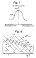
- Fig. 1 illustrates the nonlinear characteristics of the reproduced RF signal level as a function of track deviation.
- the gain must be larger at point 50A than, for example, at point 50B.
- a drive amplifier to drive a motor as one of the elements for setting the gain of a servo system is provided in a servo loop. Since the gain corresponding to point 50A is large, the gain of the drive amplifier can be relatively small. On the other hand, since the gain corresponding to point 50B is small, the gain of the drive amplifier must be relatively large.
- the gain of the drive amplifier may be so small at point 50B that an off-track indication occurs.
- the gain of the servo system may be so large at point 50A that an oscillation occurs. The servo characteristics thus deteriorate, and it is difficult to carry out the tracking control in a manner that is stable and reliable.
- An object of the invention is to provide apparatus for reproducing a video signal in such a manner as to carry out stable tracking control.
- apparatus for reproducing a video signal recorded on a tape in successive oblique tracks comprising: means for advancing the tape; rotary heads for scanning the tracks successively to form a reproduced radio frequency signal, there being a possible scanning deviation of the heads from successively scanned tracks and the reproduced signal having a level that exhibits a non-linearity as a function of the deviation; signal level detecting means for detecting a change in the level of the reproduced signal and producing an output signal indicative of the change; means for controlling the speed of advance of the tape so as to maximise the level of the reproduced signal; and gain correcting means responsive to the reproduced signal for controlling the gain to compensate for the nonlinearity.
- apparatus for reproducing a video signal recorded on a tape in successive oblique tracks comprising: means for advancing the tape; rotary heads for scanning the tracks successively to form a reproduced radio frequency signal, there being a possible scanning deviation of the heads from successively scanned tracks and the reproduced signal having a level that exhibits a nonlinearity as a function of the deviation; means for generating a vibration signal for periodically changing the speed of advance of the tape; means for producing an envelope signal corresponding to the reproduced signal; means for synchronously detecting the vibration signal and the envelope signal to produce a deviation signal corresponding to the deviation and for mixing the deviation signal and the vibration signal; and means for controlling the speed of the rotary heads in response to the vibration signal so as substantially to eliminate speed fluctuations of the heads caused by a periodic change in the tape speed.
- apparatus for recording a video signal in successive oblique tracks on a tape comprising: means for advancing the tape; rotary heads for scanning the tape along successive oblique paths to form a recorded signal; speed servo means for rotating the rotary heads at a predetermined speed; and switching means for supplying a gain to the speed servo means that has a relatively small value in the absence of relatively large G forces and a relatively large value in the presence of relatively large G forces.
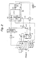
- magnetic heads 1 and 10 are attached to a rotary drum 2 and driven by a motor 3 that is directly coupled thereto.
- a rotational phase pulse generator or PG 4 and a frequency signal generator or FG 5 are coupled to the motor 3.
- the running speed of a magnetic tape T wound around the rotary drum 2 over a predetermined arc is controlled by a capstan 6.
- a motor 7 is directly coupled to the capstan 6, and an FG 8 is coupled thereto.
- a reproduced RF signal is supplied from the magnetic heads 1 and 10 through an amplifier 11 to an envelope detector 12, and an envelope signal S1 is generated.
- the envelope signal S1 is supplied both to one terminal of a comparator 13 and to a digital servo control circuit 20.
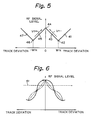
- Figs. 4 and 5 show an idealized relation between the tracking of the magnetic heads 1 and 10 and the reproduced RF signal level.
- Fig. 5 shows an ideal linear dependence of the RF signal level on track deviation; in Fig. 6, the RF signal level (shown in a heavy solid line) actually varies nonlinearly as a function of track deviation.
- the width Wh (Fig. 4) of each of the magnetic heads 1 and 10 is set to be equal to the track width Wtk.
- the relative positions between the magnetic heads 1 and 10 and tracks are represented by the following states.
- the level of the reproduced RF signal from the magnetic heads 1 and 10 in each state in Fig. 4 changes as shown in Fig. 5, in which a track deviation to the upstream side corresponds to the positive direction on the horizontal axis.
- the running speed Vt (Figs. 4 and 5) of the magnetic tape T is increased or decreased so as to obtain state 44, in which the reproduced RF signal level becomes maximum. That is, in a case where the tracking deviates to the upstream side as shown in state 43, the running speed Vt of the magnetic tape T is decelerated as shown by an arrow Vt- in Fig. 5. On the other hand, in a case where the tracking deviates to the downstream side as shown in state 45, the running speed Vt of the magnetic tape T is accelerated as shown by an arrow Vt+ in Fig. 5.
- Vh denotes a track scanning speed of the magnetic heads 1 and 10.
- the envelope signal S1 produced as an output by the envelope detector 12 is supplied through an A/D (analog-to-digital) converting circuit 22 to a CPU (central processing unit) 21 of the digital servo control circuit (microcomputer) 20.
- A/D analog-to-digital
- CPU central processing unit
- Outputs of the PG 4 and FG 5 coupled to the rotary drum 2 are supplied to a timer 23 of the digital servo control circuit 20.
- An output of the timer 23 is supplied to the CPU 21.
- a tracking control output CX is supplied from the CPU 21 through a D/A (digital-to-analog) converting circuit 24 to the drive amplifier 9 that controls the capstan motor 7.
- the detection output envelope signal S1 which is supplied from the envelope detector 12 is compared with a reference power source Vref by the comparator 13.
- a control signal SC of high level is supplied to the drive amplifier 9.
- a control signal SC of low level is supplied to the drive amplifier 9.
- the gain of the drive amplifier 9 is controlled by the control signal SC.
- the gain of the drive amplifier 9 is set to a low value.
- the gain of the drive amplifier 9 is set to a high value. In this manner, the gain of the servo system is properly adjusted.
- the gain of the drive amplifier 9 is set to one of two levels respectively corresponding to high and low levels of the reproduced RF signal.
- the invention is not limited to such an embodiment; the gain can also be set to one of three levels or one of any number of levels. It is in fact possible to construct the apparatus in a manner such that data to correct for the nonlinear characteristics of the reproduced RF signal level (shown by the solid line in Fig. 6) are stored in a ROM (read-only memory) and the nonlinear characteristics are continuously corrected on the basis of such data.
- the data used for such a correction are represented in Fig. 6 by a broken line formed by alternating long and short dashes.
- the tracking control output CX as converted to analog form by the D/A converting circuit 24 is amplified with a predetermined gain by the drive amplifier 9 and supplied to the capstan motor 7.
- An output of the FG 8 associated with the capstan 6 is supplied to the digital servo control circuit 20, and ordinary capstan servo control is carried out.
- An output of the digital servo control circuit 20 is supplied to the motor 3 and ordinary drum servo control is carried out.
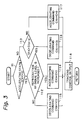
- the CPU 21 determines whether or not the magnetic tape T is being accelerated: that is, whether or not the tracking control output CXn in the present field is positive. This determination is made on the basis of the PG pulse from the PG 4, for instance, once every field (step 111).
- step 111 a check is made to see whether or not the reproduced RF signal level in the present field has increased as compared with the reproduced RF signal level in the preceding field: that is, the magnitudes of outputs S1n and S1n-1 in the present and preceding fields of the envelope detector 12 are compared (steps 112 and 113).
- the tracking condition is divided into four states.
- the tracking control output CX from the CPU 20 corresponding to each state is given below.
- a tracking control output CXn+1 > 0 of a positive polarity for acceleration is supplied as an output so that the magnetic heads 1 and 10 are subsequently controlled in the same direction (step 114).
- a tracking control output CXn+1 ⁇ 0 of a negative polarity for deceleration is supplied as an output so that the magnetic heads 1 and 10 are subsequently controlled in the stabilizing direction (step 115).
- the magnetic heads 1 and 10 are known to be set in the tracking state 43 shown in Figs. 4 and 5, and the magnetic heads 1 and 10 are being controlled in a stabilizing direction. Therefore, the tracking control output CXn+1 ⁇ 0 of a negative polarity for deceleration is supplied as an output so that the magnetic heads 1 and 10 are subsequently controlled in the same direction (step 116).
- the magnetic heads 1 and 10 are known to be set in the tracking state 45 shown in Figs. 4 and 5, and the magnetic heads 1 and 10 are being controlled in a direction opposite to the stabilizing direction. Therefore, the tracking control output CXn+1 > 0 of a positive polarity for acceleration is supplied as an output so that the magnetic heads 1 and 10 are subsequently controlled in the stabilizing direction (step 117).
- the error signal generated at step 118 in accordance with the appropriate tracking control outputs CX in steps 114 to 117 is supplied to the drive amplifier 9 for the capstan motor 7.
- the error signal thus supplied is amplified by the drive amplifier 9 in which the gain has been properly adjusted in accordance with the reproduced RF signal level and supplied to the motor 7.
- the track deviation is thus corrected.
- the increase or decrease in the reproduced RF signal level is detected, and the running speed of the magnetic tape T is controlled on the basis of the result of the detection. Further, the nonlinear characteristics of the change in the reproduced RF signal level are corrected, and the gain of the drive amplifier 9 is adjusted accordingly. Therefore, stable tracking control can be carried out.
- the apparatus has been described as reacting only to the polarity of the tracking control output CX, the invention is not limited to such an embodiment.
- the apparatus in a manner such that the maximum value of the reproduced RF signal level which has previously been stored is employed as a reference value and the amplitude of the tracking control output CX can be determined in accordance with the difference between the reference value and the reproduced RF signal level.
- the polarity may be made different at a predetermined amplitude, such as +0.1 V and -0.1 V.
- the invention can be similarly applied to a digital audio tape recorder of the helical-scan type.
- magnetic heads 1 and 10 each having the same width as the track width Wtk (Fig. 4) are used in the apparatus of Fig. 2, magnetic heads having widths greater than the track width Wtk can optionally be used. In that case, a tracking control system as disclosed in Japanese laid-open patent publication No. 62-222459 may be employed.
- the tape speed is periodically changed by supplying a vibration signal of a few Hz to tens of Hz to a capstan motor, the magnetic head relatively vibrates (wobbles) in the width direction of the track, and an envelope of the reproduced RF signal is obtained wherein there are periodic changes.
- tracking control is carried out.
- the vibration of the magnetic tape i.e., the fluctuation of the tape speed
- This second embodiment of the invention can prevent the vibration of the magnetic tape from being harmfully propagated to the rotary drum.
- the second embodiment of the invention is shown in Fig. 7.
- a reproduced RF signal obtained in a head-tape system similar to the one employed in the embodiment described above is supplied to an input terminal 61.
- the reproduced RF signal including an error component ⁇ (t) corresponding to a track deviation is supplied through an amplifier 62 to an envelope detecting circuit 63.
- the direction of movement of the magnetic tape T is shown by an arrow A in Fig. 8 and is set to be identical to the direction of rotation (shown by an arrow B in Fig. 8) of a rotary drum 2.
- An envelope of the reproduced RF signal is detected by the detecting circuit 63, and an envelope signal S1 is derived as a detection output which is expressed by (sin( ⁇ 0t + ⁇ (t))).
- the envelope signal S1 is supplied to a multiplying circuit 64.
- a vibration signal S2 of a low frequency which is expressed by (sin ⁇ 0t) is supplied from a vibration signal generating circuit 65 to delay circuits 66 and 67 and an adding circuit 68.
- the delay circuits 66 and 67 are provided to compensate for time delays of a capstan motor 7 and a drum motor 3, respectively. Since the inertia of the drum motor 3 is larger than the inertia of the capstan motor 7, the delay amount of the delay circuit 67 is set to be larger than the delay amount of the delay circuit 66.
- the second item (cos(2 ⁇ 0t + ⁇ (t))) in the detection output which is expressed by the right side of equation (1) corresponds to harmonics that are caused by the synchronous detection.
- the harmonics are eliminated by the low pass filter 69. Only the component of the remaining first item (1/2)(cos(- ⁇ (t))) in the right side is supplied to the adding circuit 68 as a signal S3 indicative of the detection output.
- the signal S3 which is supplied from the low pass filter 69 and the vibration signal S2 which is supplied from the vibration signal generating circuit 65 are added by the adding circuit 68.
- the signal S3 which has an error component ⁇ (t) and is expressed by (1/2)cos(- ⁇ (t)) and the vibration signal S2 are added, and the resultant signal is supplied to an adding circuit 70 at the next stage.
- the sum of the signal S3 and the vibration signal S2 is produced as an output by the adding circuit 68.
- This sum and an error signal which is supplied from a period detecting circuit 74 are supplied to an adding circuit 70 (the error signal is explained below).
- the adding circuit 70 adds these signals to produce a control signal S4.
- the control signal S4 is supplied to the capstan motor 7 through a drive amplifier 71.
- the capstan motor 7 is controlled by the control signal S4.
- a frequency signal generator (FG) 8 is coupled to the capstan motor 7. An output signal from the FG 8 is supplied to the period detecting circuit 74 through an amplifier 73.
- the period of the output signal from the FG 8 is detected by the period detecting circuit 74.
- An error signal having a level corresponding to the detected period is formed.
- the error signal is supplied to the adding circuit 70.
- the rotational speed of the capstan motor 7 is controlled by the control signal S4. That is, the rotational speed of the capstan motor 7 is periodically changed on the basis of the vibration signal S2, and the track deviation expressed by the error component ⁇ (t) is controlled so as to be canceled.
- the vibration signal S2 which is expressed by (sin ⁇ 0t) is supplied from the delay circuit 67 to an inverting circuit 75.
- the inverting circuit 75 by inverting the phase of the delayed vibration signal S2, forms a vibration signal S5.
- the vibration signal S5 is supplied to an adding circuit 76.
- the adding circuit 76 adds the vibration signal S5 and a speed error signal Ssp which is supplied from a low pass filter 81 to produce a control signal S6.
- the speed error signal Ssp is explained below.
- the control signal S6 is supplied to the drum motor 3 through a drive amplifier 77.
- the drum motor 3 is controlled by the control signal S6.
- a frequency signal generator FG 5 is coupled to the drum motor 3.
- An output signal from the FG 5 is supplied through an amplifier 79 to a period detecting circuit 80.
- the frequency of the output signal from the FG 5 is set to be, for instance, 180 Hz when the rotational speed of the rotary drum 2 (Fig. 2) reaches a reference rotational speed.
- the period detecting circuit 80 the period of the output signal of the FG 5 is detected and a speed error signal Ssp having a level corresponding to the detected period is formed.
- the drum motor 3 is driven at the reference rotational speed on the average by the speed error signal Ssp.
- the speed error signal Ssp is supplied to the adding circuit 76 through the low pass filter 81 as mentioned above.
- a drum speed servo system comprising the drum motor 3, FG 5, period detecting circuit 80, a low pass filter 81, the rotational speed of the drum motor 3 is controlled by the control signal S6. That is, a periodic fluctuation of the rotational speed of the drum motor 3 on the basis of the vibration signal S2 is prevented.
- the vibration signal S2 is included in the control signal S4 which is supplied to the capstan motor 7.
- the rotational speed of the capstan motor 7 is periodically changed on the basis of the vibration signal S2. Therefore, the tape speed of the magnetic tape T is periodically changed and wobbled.
- the vibration signal S5 whose phase is opposite to that of the vibration signal S2 is included in the control signal S6 which is supplied to the drum motor 3. Therefore, the fluctuation in the rotational speed of the drum motor 3 due to the speed fluctuation in tape speed is canceled by the signal S5. It is thus possible to prevent the vibration from being propagated to the drum motor 3. Therefore, jitter and a consequent deterioration in the quality of the reproduced image can both be prevented.
- the direction of rotation of the rotary drum 2 substantially coincides with the direction of movement of the magnetic tape T.
- the invention is not limited to such an embodiment but can also be applied to the case where the direction of rotation of the rotary drum 2 is opposite to the direction of movement of the magnetic tape T. In this case, there is no need to employ the inverting circuit 75, since the phase of the vibration signal S2 does not need to be inverted.
- the vibration signal is supplied to the drum motor in such a way as to cancel the speed fluctuation caused by the periodic change in tape speed, it is possible to prevent the fluctuation in the speed of the tape from being propagated to the rotary drum. Jitter is therefore prevented, and the deterioration in quality of the reproduced image that would otherwise occur is avoided.
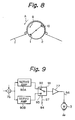
- Fig. 9 shows another embodiment of the invention.
- the embodiment of Fig. 9 is described taking the control of the drum motor 3 of the embodiment of Fig. 8 mentioned above as an example.
- Fig. 9 is suitable for a VTR integrated type camera.
- VTR integrated type cameras are now widely used, sometimes under severe conditions. For instance, sometimes the camera is used by a photographer who is running, who is taking pictures through the window of a moving vehicle, or who is riding on a roller coaster, etc.
- the output signal of the adding circuit 76 is used as a speed servo signal for the drum motor 3.
- the output signal of the adding circuit 76 is supplied to servo amplifiers 90A and 90B, respectively, as shown in Fig. 9.
- each of the servo amplifiers 90A and 90B has a phase compensating circuit.
- the output signal of the adding circuit 76 is amplified by a predetermined gain and supplied to a switching circuit 91.
- the gains of the servo amplifiers 90A and 90B are set to Ga and Gb, respectively, where Ga > Gb.
- the error signal amplified by the gain Ga is supplied from the servo amplifier 90A to a terminal 92 of a switching circuit 91.
- the error signal amplified by the gain Gb is supplied from the servo amplifier 90B to a terminal 93 of the switching circuit 91.
- the state of the switching circuit 91 is controlled by a control signal S7 from a terminal 94.
- the control signal S7 is set by a manual switch which is operated by the photographer in accordance with the conditions under which the camera is being used. Under ordinary or normal photographing conditions, the control signal S7 is set to, for instance, "0" (low level). In this case, the terminal 93 of the switching circuit 91 is connected to select the relatively low gain Gb.
- the error signal from the servo amplifier 90B is selected by the switching circuit 91 and is provided as an output. On the other hand, under severe photographing conditions in which the G forces are high, the control signal S7 is set to "1" (high level). The terminal 92 of the switching circuit 91 is then connected to select the relatively high gain Ga.
- the error signal from the servo amplifier 90A is selected by the switching circuit 91 and is supplied as an output.
- the error signal selected by the switching circuit 91 is supplied to the drum motor 3 through an amplifier 77. In this way, the rotational speed of the drum motor 3 is effectively controlled regardless of whether or not the camera is subjected to high G forces.
- the suppressing characteristics of the drum speed servo system when operating under the influence of high G forces in the lateral direction are improved.
- the rotational speed of the rotary drum is maintained at the desired rotational speed, and the oscillation of the image resulting from jitter and the deviation of the chroma APC (automatic phase control) are prevented.
- a situation such that no color appears in the image is also avoided. It is possible to prevent a situation in which one horizontal period becomes so long that the synchronization is not carried out.
- the disturbance is eliminated, normal recording can be carried out, and a normal reproduced image can be obtained.
- the frequency of the output signal from the FG 5 can be also switched from 180 Hz in the normal mode to 720 Hz in the vibrating mode.
- the switching circuit 91 is operated manually.
- the vibration can be detected automatically by a vibration detecting sensor and the switching circuit 91 controlled in accordance with the detected result.
- the occurrence of a disturbance can be detected automatically by measuring the phase difference between a sync signal and an FG pulse, and the switching circuit 91 can be controlled accordingly.
- the servo amplifiers 90A and 90B can be constructed as a single amplifier having a controllable gain, the gain having a value that is selected by the control signal S7.
Landscapes
- Adjustment Of The Magnetic Head Position Track Following On Tapes (AREA)
Applications Claiming Priority (6)
| Application Number | Priority Date | Filing Date | Title |
|---|---|---|---|
| JP1073634A JP2626039B2 (ja) | 1989-03-24 | 1989-03-24 | 磁気記録再生装置 |
| JP73634/89 | 1989-03-24 | ||
| JP72961/89 | 1989-03-25 | ||
| JP1072961A JP2661250B2 (ja) | 1989-03-25 | 1989-03-25 | ドラムサーボ回路 |
| JP75999/89 | 1989-03-28 | ||
| JP1075999A JP2629345B2 (ja) | 1989-03-28 | 1989-03-28 | サーボ回路 |
Publications (3)
| Publication Number | Publication Date |
|---|---|
| EP0389293A2 true EP0389293A2 (fr) | 1990-09-26 |
| EP0389293A3 EP0389293A3 (fr) | 1993-03-03 |
| EP0389293B1 EP0389293B1 (fr) | 1996-01-10 |
Family
ID=27301086
Family Applications (1)
| Application Number | Title | Priority Date | Filing Date |
|---|---|---|---|
| EP90303124A Expired - Lifetime EP0389293B1 (fr) | 1989-03-24 | 1990-03-23 | Signal R.F. d'asservissement de suivi de piste pour magnétoscope |
Country Status (3)
| Country | Link |
|---|---|
| US (1) | US5119246A (fr) |
| EP (1) | EP0389293B1 (fr) |
| DE (1) | DE69024686T2 (fr) |
Cited By (1)
| Publication number | Priority date | Publication date | Assignee | Title |
|---|---|---|---|---|
| DE4135254A1 (de) * | 1991-10-25 | 1993-04-29 | Thomson Brandt Gmbh | Verfahren zur spurfolgesteuerung in einem videorecorder |
Families Citing this family (6)
| Publication number | Priority date | Publication date | Assignee | Title |
|---|---|---|---|---|
| JPH03205640A (ja) * | 1989-12-30 | 1991-09-09 | Sony Corp | トラツクずれ量補正回路 |
| KR920004224B1 (ko) * | 1989-12-31 | 1992-05-30 | 삼성전자 주식회사 | A/c헤드의 x거리 무조정방식의 자기기록 재생장치 |
| JP2728544B2 (ja) * | 1990-05-18 | 1998-03-18 | 株式会社日立製作所 | 磁気記録再生装置の自動トラッキング装置 |
| JPH04311854A (ja) * | 1991-04-11 | 1992-11-04 | Sony Corp | トラッキング調整回路 |
| JPH06338106A (ja) * | 1993-05-28 | 1994-12-06 | Canon Inc | トラッキング制御装置 |
| US6144518A (en) * | 1997-04-30 | 2000-11-07 | Exabyte Corporation | Preparation and usage of dual-scan master calibration tape for magnetic tape drive |
Citations (7)
| Publication number | Priority date | Publication date | Assignee | Title |
|---|---|---|---|---|
| FR2089078A5 (fr) * | 1970-04-06 | 1972-01-07 | Ampex | |
| EP0169479A2 (fr) * | 1984-07-17 | 1986-01-29 | Hitachi, Ltd. | Procédé et dispositif de poursuite de piste automatique pour appareil d'enregistrement et de reproduction magnétique |
| EP0181186A2 (fr) * | 1984-11-02 | 1986-05-14 | Victor Company Of Japan, Limited | Système de commande de centrage |
| JPS61276158A (ja) * | 1985-05-31 | 1986-12-06 | Sony Corp | サ−ボ回路 |
| US4794473A (en) * | 1986-05-29 | 1988-12-27 | Pioneer Electronic Corporation | Fast mode reel servo in a magnetic recording/reproducing apparatus |
| EP0302696A2 (fr) * | 1987-08-04 | 1989-02-08 | Mitsubishi Denki Kabushiki Kaisha | Contrôle de piste pour appareil d'enregistrement et/ou de reproduction magnétique |
| JPS6443881A (en) * | 1987-08-11 | 1989-02-16 | Fujitsu Ltd | Magnetic disk device |
Family Cites Families (1)
| Publication number | Priority date | Publication date | Assignee | Title |
|---|---|---|---|---|
| US4319289A (en) * | 1978-03-23 | 1982-03-09 | Ampex Corporation | Movable head automatic position acquisition circuit and method |
-
1990
- 1990-03-20 US US07/496,528 patent/US5119246A/en not_active Expired - Lifetime
- 1990-03-23 EP EP90303124A patent/EP0389293B1/fr not_active Expired - Lifetime
- 1990-03-23 DE DE69024686T patent/DE69024686T2/de not_active Expired - Fee Related
Patent Citations (7)
| Publication number | Priority date | Publication date | Assignee | Title |
|---|---|---|---|---|
| FR2089078A5 (fr) * | 1970-04-06 | 1972-01-07 | Ampex | |
| EP0169479A2 (fr) * | 1984-07-17 | 1986-01-29 | Hitachi, Ltd. | Procédé et dispositif de poursuite de piste automatique pour appareil d'enregistrement et de reproduction magnétique |
| EP0181186A2 (fr) * | 1984-11-02 | 1986-05-14 | Victor Company Of Japan, Limited | Système de commande de centrage |
| JPS61276158A (ja) * | 1985-05-31 | 1986-12-06 | Sony Corp | サ−ボ回路 |
| US4794473A (en) * | 1986-05-29 | 1988-12-27 | Pioneer Electronic Corporation | Fast mode reel servo in a magnetic recording/reproducing apparatus |
| EP0302696A2 (fr) * | 1987-08-04 | 1989-02-08 | Mitsubishi Denki Kabushiki Kaisha | Contrôle de piste pour appareil d'enregistrement et/ou de reproduction magnétique |
| JPS6443881A (en) * | 1987-08-11 | 1989-02-16 | Fujitsu Ltd | Magnetic disk device |
Non-Patent Citations (2)
| Title |
|---|
| PATENT ABSTRACTS OF JAPAN vol. 011, no. 137 (P-572), 2 May 1987; & JP - A - 61276158 (SONY CORP) 06.12.1986 * |
| PATENT ABSTRACTS OF JAPAN vol. 013, no. 239 (P-879), 6 June 1989; & JP - A - 1043881 (FUJITSU LTD) 16.02.1989 * |
Cited By (1)
| Publication number | Priority date | Publication date | Assignee | Title |
|---|---|---|---|---|
| DE4135254A1 (de) * | 1991-10-25 | 1993-04-29 | Thomson Brandt Gmbh | Verfahren zur spurfolgesteuerung in einem videorecorder |
Also Published As
| Publication number | Publication date |
|---|---|
| DE69024686D1 (de) | 1996-02-22 |
| EP0389293B1 (fr) | 1996-01-10 |
| EP0389293A3 (fr) | 1993-03-03 |
| US5119246A (en) | 1992-06-02 |
| DE69024686T2 (de) | 1996-06-27 |
Similar Documents
| Publication | Publication Date | Title |
|---|---|---|
| EP0050024B1 (fr) | Système de correction de l'erreur de centrage de la tête dans un appareil de reproduction vidéo | |
| US4370685A (en) | Head tracking control system for a helical scan VTR | |
| US5119246A (en) | Rf tracking servo for vtr with adjustable servo loop gain | |
| US4549234A (en) | Method and apparatus for tracking control | |
| EP0041868B1 (fr) | Système de traitement de signaux vidéo | |
| US4590523A (en) | Control of auto-tracking in tracking-error correcting system of video recording/reproducing apparatus | |
| US5157513A (en) | Circuit and method for reducing the timebase correction requirements of an optical videodisc player in scan mode | |
| US5758010A (en) | Reproducing apparatus with time base corrector | |
| US4459620A (en) | Color video signal reproducing apparatus | |
| US4542416A (en) | System for eliminating vertical TV picture fluctuations appearing in monitored video signals from a VTR | |
| US5760988A (en) | Tracking method and apparatus used in helical scan magnetic recording/reproducing system | |
| US5448367A (en) | Apparatus for automatically controlling generation of a head switching signal | |
| KR950000419B1 (ko) | 자기 기록재생 장치용 자동 트래킹 시스템 | |
| EP0419370B1 (fr) | Dispositif de reproduction d'un signal numérique enregistré sur une bande magnétique | |
| KR0152045B1 (ko) | 디지탈브이시알의 가변속 재생장치 | |
| US5459622A (en) | Device for controlling the rotation of the head drum | |
| JP2629352B2 (ja) | 回転ヘッド型再生装置 | |
| JP2626057B2 (ja) | 回転ヘッド型再生装置 | |
| KR940008095B1 (ko) | 비디오 카세트 레코더(vcr)의 드럼 및 캡스턴 모터속도 보정장치 | |
| JP2661250B2 (ja) | ドラムサーボ回路 | |
| JP2626039B2 (ja) | 磁気記録再生装置 | |
| KR0170258B1 (ko) | 비데오 테이프 레코더의 캡스턴 모터 제어방법 | |
| JP3309082B2 (ja) | トラッキング方法および再生装置および記録再生装置のトラッキング装置 | |
| JP2626050B2 (ja) | 回転ヘッド型再生装置 | |
| JPS58139350A (ja) | テ−プ走行制御装置 |
Legal Events
| Date | Code | Title | Description |
|---|---|---|---|
| PUAI | Public reference made under article 153(3) epc to a published international application that has entered the european phase |
Free format text: ORIGINAL CODE: 0009012 |
|
| AK | Designated contracting states |
Kind code of ref document: A2 Designated state(s): DE FR GB NL |
|
| PUAL | Search report despatched |
Free format text: ORIGINAL CODE: 0009013 |
|
| AK | Designated contracting states |
Kind code of ref document: A3 Designated state(s): DE FR GB NL |
|
| 17P | Request for examination filed |
Effective date: 19930709 |
|
| 17Q | First examination report despatched |
Effective date: 19940322 |
|
| GRAA | (expected) grant |
Free format text: ORIGINAL CODE: 0009210 |
|
| AK | Designated contracting states |
Kind code of ref document: B1 Designated state(s): DE FR GB NL |
|
| REF | Corresponds to: |
Ref document number: 69024686 Country of ref document: DE Date of ref document: 19960222 |
|
| ET | Fr: translation filed | ||
| PLBE | No opposition filed within time limit |
Free format text: ORIGINAL CODE: 0009261 |
|
| STAA | Information on the status of an ep patent application or granted ep patent |
Free format text: STATUS: NO OPPOSITION FILED WITHIN TIME LIMIT |
|
| 26N | No opposition filed | ||
| REG | Reference to a national code |
Ref country code: GB Ref legal event code: IF02 |
|
| PGFP | Annual fee paid to national office [announced via postgrant information from national office to epo] |
Ref country code: FR Payment date: 20020312 Year of fee payment: 13 |
|
| PGFP | Annual fee paid to national office [announced via postgrant information from national office to epo] |
Ref country code: GB Payment date: 20020327 Year of fee payment: 13 |
|
| PGFP | Annual fee paid to national office [announced via postgrant information from national office to epo] |
Ref country code: NL Payment date: 20020328 Year of fee payment: 13 |
|
| PGFP | Annual fee paid to national office [announced via postgrant information from national office to epo] |
Ref country code: DE Payment date: 20020404 Year of fee payment: 13 |
|
| PG25 | Lapsed in a contracting state [announced via postgrant information from national office to epo] |
Ref country code: GB Free format text: LAPSE BECAUSE OF NON-PAYMENT OF DUE FEES Effective date: 20030323 |
|
| PG25 | Lapsed in a contracting state [announced via postgrant information from national office to epo] |
Ref country code: NL Free format text: LAPSE BECAUSE OF NON-PAYMENT OF DUE FEES Effective date: 20031001 Ref country code: DE Free format text: LAPSE BECAUSE OF NON-PAYMENT OF DUE FEES Effective date: 20031001 |
|
| GBPC | Gb: european patent ceased through non-payment of renewal fee |
Effective date: 20030323 |
|
| PG25 | Lapsed in a contracting state [announced via postgrant information from national office to epo] |
Ref country code: FR Free format text: LAPSE BECAUSE OF NON-PAYMENT OF DUE FEES Effective date: 20031127 |
|
| NLV4 | Nl: lapsed or anulled due to non-payment of the annual fee |
Effective date: 20031001 |
|
| REG | Reference to a national code |
Ref country code: FR Ref legal event code: ST |