EP0384954B1 - Gelenkschutz für Leitern - Google Patents
Gelenkschutz für Leitern Download PDFInfo
- Publication number
- EP0384954B1 EP0384954B1 EP89114648A EP89114648A EP0384954B1 EP 0384954 B1 EP0384954 B1 EP 0384954B1 EP 89114648 A EP89114648 A EP 89114648A EP 89114648 A EP89114648 A EP 89114648A EP 0384954 B1 EP0384954 B1 EP 0384954B1
- Authority
- EP
- European Patent Office
- Prior art keywords
- hinge
- joint
- protector according
- sleeve portion
- side rail
- Prior art date
- Legal status (The legal status is an assumption and is not a legal conclusion. Google has not performed a legal analysis and makes no representation as to the accuracy of the status listed.)
- Expired - Lifetime
Links
Images

Classifications
-
- E—FIXED CONSTRUCTIONS
- E06—DOORS, WINDOWS, SHUTTERS, OR ROLLER BLINDS IN GENERAL; LADDERS
- E06C—LADDERS
- E06C1/00—Ladders in general
- E06C1/02—Ladders in general with rigid longitudinal member or members
- E06C1/38—Special constructions of ladders, e.g. ladders with more or less than two longitudinal members, ladders with movable rungs or other treads, longitudinally-foldable ladders
- E06C1/39—Ladders having platforms; Ladders changeable into platforms
- E06C1/393—Ladders having platforms foldable with the ladder
Definitions
- the invention relates to a joint protection for step or step ladders with support legs and cheeks or bars.
- Such ladders regularly have two joints, which are arranged in the upper region of the ladder. Since these joints are usually freely accessible, they can also be contaminated, which can lead to wear on the joints. There is also a risk that the user can get his fingers into the interior of the joint, which can lead to injuries.
- the invention has for its object to develop the step or step ladder so that their joints are adequately protected.
- a cover piece which surrounds the joint and can be connected to the cheek or the one spar, and to which a sleeve section which can be connected to the cover piece and which connects the end piece of the support leg which faces the joint is connected or other Holmes at least partially covers.
- the invention is implemented in any case if each joint of the conductor in question is surrounded by a protective joint which can follow the movements of the actual joint. So that's the real thing Joint of the conductor is no longer easily accessible from the outside, so that no contaminants can get into the joint. It is also excluded that the user unexpectedly sticks his fingers in the inner region of the joint and thus jams.
- a particularly advantageous embodiment provides that the axial length of the sleeve section can be changed. It is expedient here if the sleeve section is designed as a bellows which surrounds the end piece without a gap.
- the advantage of a bellows-like sleeve section is that such parts can easily follow the joint movements and without major wear.
- a further expedient embodiment of the invention provides that the outside of the sleeve section has transverse grooves running transversely to the end piece and at a distance from one another. If the ends of the circumferential grooves formed in the region of the joint are directed towards the cover piece, then the deformation of the joint protection takes place in the region of the joint without major material stress. These measures can only be taken so that the joint between the cover and the outside of the sleeve section is formed by an arcuate groove, the radius of curvature of which corresponds to the distance of the groove from the joint axis of the conductor joint. This groove and the grooves running into this groove form an artificial weak point in the joint protection, as a result of which the joint protection can be deformed in a targeted manner in the region of the joint.
- the cover piece consists of two the joint on the outside surrounding legs, between which is arranged a tongue-shaped continuation of the sleeve section, which covers the slot.
- a particularly expedient embodiment of the invention provides that the joint protection is formed in one piece and consists of two components.
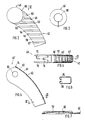
- the stepladder 12 has two joints 30, each of which is covered with a joint protection 10.
- the joint protection 10 has a cover piece 40 which surrounds the joint 30 and which can be fixedly connected to the cheek 16, to which is connected a sleeve section 42 which can be connected in an articulated manner to the cover piece 40 and which at least partially covers the end piece of the support leg 20 facing the joint 30.
- the axial length of the sleeve section 42 can be changed.
- the sleeve section 42 could generally be designed as a bellows which surrounds the end piece without a gap.
- the sleeve section 42 is provided with circumferential grooves 50 to 57 which run transversely to the end piece and at a distance from one another.
- the ends of the circumferential grooves 51, 52 and 53 formed in the region of the joint 30 are directed towards the cover piece 40.
- the joint 60 between the cover 40 and the outside of the sleeve section 42 is formed by an arcuate groove 60, the radius of curvature of which corresponds to the distance of the groove from the joint axis of the conductor joint 30.
- the cover piece 40 has a central bore 80 which can be covered by a cap. 5, the bore 82 is laterally offset.
- the protection shown in the figures is particularly suitable for a step ladder, in which a slot is formed in the narrow sides of the cheeks 14 and 16, into which the upper end of the respective support leg engages to form a joint.
- the cover 40 consists of two the joint 30 on the outside surrounding legs 70 and 72, between which a continuation in the form of a tongue 74 of the sleeve section 42 is arranged, which covers the slot.
- the cover 40 is circular in plan view and curved outwards, so that it can be slipped onto the hinge pin of the hinge 30, not shown, and can be snapped on.
- the cover 40 according to FIG. 3 has a radial groove 7 so that the diameter of the recess 80 can be increased.
- the joint protection consisting of two different plastics, appears to the user as the actual joint, which enables a gap-free and slot-free connection between the cheeks and the support legs assigned to them. Impurities cannot get into the joint because it is covered on all sides.
- the plastics are selected so that at least the sleeve section 42 consists of elastic plastic, so that this can follow the pivoting movement of the support leg 20 or other spars by deformation.
Landscapes
- Ladders (AREA)
- Steps, Ramps, And Handrails (AREA)
Description
- Die Erfindung betrifft einen Gelenkschutz für Stufen- oder Stehleitern mit Stützschenkeln und Wangen bzw. Holmen.
- Solche Leitern besitzen regelmäßig zwei Gelenke, die im oberen Bereich der Leiter angeordnet sind. Da diese Gelenke gewöhnlich frei zugänglich sind, können in sie auch Verunreinigungen gelangen, die zum Verschleiß der Gelenke führen können. Ferner besteht auch die Gefahr, daß der Benutzer mit seinen Fingern in den Innenbereich des Gelenkes gelangt, was zu Verletzungen führen kann.
- Ausgehend von dem obigen Stand der Technik liegt der Erfindung die Aufgabe zugrunde, die Stufen- oder Stehleitern so weiterzubilden, daß deren Gelenke hinreichend geschützt sind.
- Die gestellte Aufgabe wird erfindungsgemäß durch ein das Gelenk umgebendes und mit der Wange bzw. dem einen Holm fest bzw. gelenkig verbindbares Abdeckstück gelöst, an das sich ein mit dem Abdeckstück gelenkig bzw. fest verbindbarer Ärmelabschnitt anschließt, der das dem Gelenk zugekehrte Endstück des Stützschenkels bzw. anderen Holmes zumindest teilweise abdeckt.
- Man erkennt, daß die Erfindung jedenfalls dann verwirklicht ist, wenn jedes Gelenk der hier in Betracht kommenden Leiter von einem Schutzgelenk umgeben ist, das den Bewegungen des eigentlichen Gelenkes folgen kann. Somit ist das eigentliche Gelenk der Leiter von außen nicht mehr ohne weiteres zugänglich, so daß auch keine Verunreinigungen in das Gelenk gelangen können. Es ist auch ausgeschlossen, daß der Benutzer seine Finger unverhofft in den Innenbereich des Gelenkes steckt und somit einklemmt.
- Weitere zweckmäßige und vorteilhafte Ausgestaltungen der Erfindung gehen aus den Unteransprüchen hervor.
- Eine besonders vorteilhafte Ausgestaltung sieht vor, daß die Axiallänge des Ärmelabschnittes veränderbar ist. Hierbei ist es zweckmäßig, wenn der Ämrelabschnitt als ein Faltbalg ausgebildet ist, der das Endstück abstandsfrei umgibt. Der Vorteil eines faltbalgartigen Ärmelabschnittes besteht darin, daß solche Teile den Gelenkbewegungen problemlos und ohne größere Abnutzung folgen können.
- Eine weitere zweckmäßige Ausgestaltung der Erfindung sieht vor, daß die Außenseite des Ärmelabschnittes quer zu dem Endstück und mit Abstand zueinander laufende Umfangsnuten besitzt. Sind hierbei die Enden der im Bereich des Gelenkes ausgebildeten Umfangsnuten auf das Abdeckstück gerichtet, dann erfolgt ist die Verformung des Gelenkschutzes im Bereich des Gelenkes ohne größere Materialbeanspruchung. Hierbei können diese Maßnahmen nur so getroffen sein, daß die Stoßstelle zwischen dem Abdeckstück und der Außenseite des Ärmelabschnittes durch eine bogenförmige Nut gebildet ist, deren Krümmungsradius dem Abstand der Nut von der Gelenkachse des Leitergelenkes entspricht. Durch diese Nut und die in diese Nut auslaufenden Nuten wird eine künstliche Schwachstelle des Gelenkschutzes gebildet, wodurch eine gezielte Verformung des Gelenkschutzes im Bereich des Gelenkes erfolgen kann.
- Handelt es sich um einen Gelenkschutz für eine Stufenleiter, bei der in den Schmalseiten der Wangen jeweils ein Schlitz ausgebildet ist, in den das obere Ende des jeweiligen Stützschenkels unter Bildung eines Gelenkes eingreift, dann ist es zweckmäßig, wenn das Abdeckstück aus zwei das Gelenk außenseitig umgebenden Schenkeln besteht, zwischen denen eine in Form einer Zunge ausgebildete Fortsetzung des Ärmelabschnittes angeordnet ist, die den Schlitz abdeckt.
- Schließlich sieht eine besonders zweckmäßige Ausgestaltung der Erfindung vor, daß der Gelenkschutz einstückig ausgebildet ist und aus zwei Komponenten besteht.
- Ein Ausführungsbeispiel der Erfindung ist in der Zeichnung schematisch dargestellt und wird im folgenden näher erläutert. Es zeigen
- Fig. 1 ein Gelenk einer Stufen-Stehleiter in perspektivischer Seitenansicht,
- Fig. 2 einen Gelenkschutz in Seitenansicht,
- Fig. 3 ein Abdeckstück eines Gelenkschutzes,
- Fig. 4 den in Fig. 2 dargestellten Gelenkschutz in Richtung des Pfeiles IV,
- Fig. 5 einen Schnitt entlang der Linie V-V nach Fig. 4,
- Fig. 6 einen Schnitt entlang der Linie VI-VI nach Fig. 5,
- Fig. 7 einen Schnitt durch einen Schenkel des Abdeckschutzes vergrößert dargestellt.
- In den Figuren ist ein Gelenkschutz 10 für eine Stufenstehleiter mit Stützschenkeln 20 sowie Wangen 14 und 16 dargetellt (vgl. Fig. 1). Die Stufenstehleiter 12 besitzt zwei Gelenke 30, die mit jeweils einem Gelenkschutz 10 abgedeckt sind. Der Gelenkschutz 10 besitzt ein das Gelenk 30 umgebendes und mit der Wange 16 fest verbindbares Abdeckstück 40, an das sich ein mit dem Abdeckstück 40 gelenkig verbindbarer Ärmelabschnitt 42 anschließt, der das dem Gelenk 30 zugekehrte Endstück des Stützschenkels 20 zumindest teilweise abdeckt. Die Axiallänge des Ärmelabschnittes 42 ist veränderbar. Der Ärmelabschnitt 42 könnte allgemein als ein Faltbalg ausgebildet sein, der das Endstück abstandsfrei umgibt. Im vorliegenden Ausführungsbeispiel ist der Ärmelabschnitt 42 mit quer zu den Endstück und mit Abstand zueinander verlaufenden Umfangsnuten 50 bis 57 versehen. Die Enden der im Bereich des Gelenkes 30 ausgebildeten Umfangsnuten 51, 52 und 53 sind auf das Abdeckstück 40 gerichtet.
- Insbesondere Fig. 2 läßt erkennen, daß die Stoßstelle 60 zwischen dem Abdeckstück 40 und der Außenseite des Ärmelabschnittes 42 durch eine bogenförmige Nut 60 gebildet ist, deren Krümmungsradius dem Abstand der Nut von der Gelenkachse des Leitergelenkes 30 entspricht.
- In Fig. 3 besitzt ds Abdeckstück 40 eine mittige Bohrung 80, die durch eine Kappe abgedeckt werden kann. In Fig. 5 ist die Bohrung 82 seitlich versetzt. Der in den Fig. dargestellte Schutz eignet sich besonders für eine Stufenleiter, bei der in den Schmalseiten der Wangen 14 und 16 jeweils ein Schlitz ausgebildet ist, in den das obere Ende des jeweiligen Stützschenkels unter Bildung eines Gelenkes eingreift. Das Abdeckstück 40 besteht aus zwei das Gelenk 30 außenseitig umgebenden Schenkeln 70 und 72, zwischen denen ein in Form einer Zunge 74 ausgebildete Fortsetzung des Ärmelabschnittes 42 angeordnet ist, die den Schlitz abdeckt.
- Man erkennt, daß das Abdeckstück 40 in Draufsicht kreisrund und nach außen gewölbt ist, so daß es auf den nicht dargestellten Gelenkbolzen des Gelenkes 30 aufgestülpt und hierbei aufgerastet werden kann. Um das Aufstülpen zu erleichtern, besitzt das Abdeckstück 40 nach Fig. 3 eine Radialnut 7 so daß der Durchmesser der Ausnehmung 80 vergrößert werden kann.
- Der aus zwei unterschiedlichen Kunststoffen bestehende Gelenkschutz erscheint für den Benutzer als das eigentliche Gelenk, das eine spalt- und schlitzfreie Verbindung zwischen den Wangen und den ihnen zugeordneten Stützschenkeln ermöglicht. Verunreinigungen können in das Gelenk nicht gelangen, da es allseitig bedeckt ist. Die Kunststoffe sind so gewählt, daß zumindest der Ärmelabschnitt 42 aus elastischem Kunststoff besteht, so daß dieses der Schwenkbewegung des Stützschenkels 20 bzw. anderen Holmes durch Verformung folgen kann.
Claims (8)
Priority Applications (1)
| Application Number | Priority Date | Filing Date | Title |
|---|---|---|---|
| AT89114648T ATE70887T1 (de) | 1989-03-03 | 1989-08-08 | Gelenkschutz fuer leitern. |
Applications Claiming Priority (2)
| Application Number | Priority Date | Filing Date | Title |
|---|---|---|---|
| DE3906805A DE3906805A1 (de) | 1989-03-03 | 1989-03-03 | Gelenkschutz fuer leitern |
| DE3906805 | 1989-03-03 |
Publications (2)
| Publication Number | Publication Date |
|---|---|
| EP0384954A1 EP0384954A1 (de) | 1990-09-05 |
| EP0384954B1 true EP0384954B1 (de) | 1991-12-27 |
Family
ID=6375447
Family Applications (1)
| Application Number | Title | Priority Date | Filing Date |
|---|---|---|---|
| EP89114648A Expired - Lifetime EP0384954B1 (de) | 1989-03-03 | 1989-08-08 | Gelenkschutz für Leitern |
Country Status (5)
| Country | Link |
|---|---|
| EP (1) | EP0384954B1 (de) |
| AT (1) | ATE70887T1 (de) |
| DE (2) | DE3906805A1 (de) |
| ES (1) | ES2028423T3 (de) |
| GR (1) | GR3003885T3 (de) |
Family Cites Families (7)
| Publication number | Priority date | Publication date | Assignee | Title |
|---|---|---|---|---|
| CH192115A (de) * | 1936-12-19 | 1937-07-31 | Nauer Gottlieb | Einrichtung an Bockleitern. |
| DE1811172U (de) * | 1960-03-15 | 1960-05-12 | Eisenwerk Sauerland G M B H | Stahlrohrleiter. |
| US4027741A (en) * | 1976-07-15 | 1977-06-07 | Shakespeare Company | Locking hinge mechanism for a stepladder |
| DE8208700U1 (de) * | 1982-03-26 | 1982-08-12 | Krause, Günther, 6320 Alsfeld | Zusammenklappbare mehrzweckleiter |
| DE3521067C2 (de) * | 1984-06-18 | 1995-04-20 | Aisin Seiki | Gestell für Fahrzeugsitze |
| DE8809515U1 (de) * | 1988-07-26 | 1988-09-22 | Hailo-Werk Rudolf Loh Gmbh & Co Kg, 6342 Haiger | Gelenk für eine Mehrzweckleiter |
| DE8811247U1 (de) * | 1988-09-06 | 1988-11-10 | Hailo-Werk Rudolf Loh Gmbh & Co Kg, 6342 Haiger | Rastgelenk für eine Mehrzweckleiter |
-
1989
- 1989-03-03 DE DE3906805A patent/DE3906805A1/de not_active Withdrawn
- 1989-08-08 ES ES198989114648T patent/ES2028423T3/es not_active Expired - Lifetime
- 1989-08-08 DE DE8989114648T patent/DE58900639D1/de not_active Expired - Lifetime
- 1989-08-08 EP EP89114648A patent/EP0384954B1/de not_active Expired - Lifetime
- 1989-08-08 AT AT89114648T patent/ATE70887T1/de active
-
1992
- 1992-02-25 GR GR920400309T patent/GR3003885T3/el unknown
Also Published As
| Publication number | Publication date |
|---|---|
| GR3003885T3 (de) | 1993-03-16 |
| EP0384954A1 (de) | 1990-09-05 |
| ATE70887T1 (de) | 1992-01-15 |
| ES2028423T3 (es) | 1992-07-01 |
| DE58900639D1 (de) | 1992-02-06 |
| DE3906805A1 (de) | 1990-09-13 |
Similar Documents
| Publication | Publication Date | Title |
|---|---|---|
| DE2754422C2 (de) | Bremsanordnung für eine Kniegelenkprothese | |
| DE2742112A1 (de) | Halter fuer eine handbrause | |
| EP0657324B1 (de) | Dachreling für Fahrzeuge | |
| WO1998040644A1 (de) | Schutzelement mit einem deckel, der in zwei unterschiedliche stabile stellungen bringbar ist | |
| EP0689965B1 (de) | Dachreling für Fahrzeuge | |
| EP0784940A2 (de) | Torwarthandschuh mit Fingerkuppen-Kappen | |
| DE69723271T2 (de) | Kreuzgelenkwelle, insbesondere von teleskopischen typs, mit schutzhülle und schutzmanschette für die gabeln | |
| DE20005551U1 (de) | Hochflexibles Schlauchendstück | |
| DE3820402A1 (de) | Hinterrad-kettenumwerfer fuer eine fahrrad-kettenschaltung | |
| EP0342350B1 (de) | Durch Handkraft höhenverstellbare Kraftfahrzeuglenksäule | |
| AT391525B (de) | Vorrichtung zum befestigen von biegsamen leitungen, insbesondere von bowdenzuegen | |
| EP0384954A1 (de) | Gelenkschutz für Leitern | |
| DE8902549U1 (de) | Gelenkschutz für Leitern | |
| EP0160221B1 (de) | Bürostuhl | |
| DE3517527C2 (de) | Brillengestell mit einem Vorderteil und angelenkten Brillenflügeln | |
| DE3317382C2 (de) | Verbindung zweier, von einer Seele durchsetzter Bowdenzughüllen | |
| EP0659163B1 (de) | Handlaufeinlaufteil für den handlauf einer rolltreppe eines rollsteiges oder dgl. | |
| DE202012100445U1 (de) | Stehleiter mit Leiterfüßen | |
| DE3901818C2 (de) | ||
| DE8910424U1 (de) | Aus zumindest zwei Gehäuseteilen dichtend zusammensetzbares Gehäuse | |
| DE8108430U1 (de) | "gleitschutzkette" | |
| EP2789788B1 (de) | Stehleiter mit Leiterfüßen | |
| DE4220417A1 (de) | Mechanische Zahnstangenlenkung | |
| AT403309B (de) | Stehleiter | |
| EP0633558B1 (de) | Schulterstütze |
Legal Events
| Date | Code | Title | Description |
|---|---|---|---|
| PUAI | Public reference made under article 153(3) epc to a published international application that has entered the european phase |
Free format text: ORIGINAL CODE: 0009012 |
|
| 17P | Request for examination filed |
Effective date: 19900713 |
|
| AK | Designated contracting states |
Kind code of ref document: A1 Designated state(s): AT BE CH DE ES FR GB GR IT LI LU NL SE |
|
| 17Q | First examination report despatched |
Effective date: 19910320 |
|
| ITF | It: translation for a ep patent filed | ||
| GRAA | (expected) grant |
Free format text: ORIGINAL CODE: 0009210 |
|
| AK | Designated contracting states |
Kind code of ref document: B1 Designated state(s): AT BE CH DE ES FR GB GR IT LI LU NL SE |
|
| REF | Corresponds to: |
Ref document number: 70887 Country of ref document: AT Date of ref document: 19920115 Kind code of ref document: T |
|
| GBT | Gb: translation of ep patent filed (gb section 77(6)(a)/1977) | ||
| REF | Corresponds to: |
Ref document number: 58900639 Country of ref document: DE Date of ref document: 19920206 |
|
| ET | Fr: translation filed | ||
| REG | Reference to a national code |
Ref country code: ES Ref legal event code: FG2A Ref document number: 2028423 Country of ref document: ES Kind code of ref document: T3 |
|
| PLBE | No opposition filed within time limit |
Free format text: ORIGINAL CODE: 0009261 |
|
| STAA | Information on the status of an ep patent application or granted ep patent |
Free format text: STATUS: NO OPPOSITION FILED WITHIN TIME LIMIT |
|
| REG | Reference to a national code |
Ref country code: GR Ref legal event code: FG4A Free format text: 3003885 |
|
| 26N | No opposition filed | ||
| EPTA | Lu: last paid annual fee | ||
| EAL | Se: european patent in force in sweden |
Ref document number: 89114648.2 |
|
| PGFP | Annual fee paid to national office [announced via postgrant information from national office to epo] |
Ref country code: GR Payment date: 19960703 Year of fee payment: 8 |
|
| PG25 | Lapsed in a contracting state [announced via postgrant information from national office to epo] |
Ref country code: GR Free format text: LAPSE BECAUSE OF NON-PAYMENT OF DUE FEES Effective date: 19970831 |
|
| PGFP | Annual fee paid to national office [announced via postgrant information from national office to epo] |
Ref country code: SE Payment date: 19980615 Year of fee payment: 10 |
|
| PGFP | Annual fee paid to national office [announced via postgrant information from national office to epo] |
Ref country code: LU Payment date: 19980730 Year of fee payment: 10 |
|
| PGFP | Annual fee paid to national office [announced via postgrant information from national office to epo] |
Ref country code: ES Payment date: 19980806 Year of fee payment: 10 |
|
| PGFP | Annual fee paid to national office [announced via postgrant information from national office to epo] |
Ref country code: GB Payment date: 19980807 Year of fee payment: 10 |
|
| PGFP | Annual fee paid to national office [announced via postgrant information from national office to epo] |
Ref country code: FR Payment date: 19980827 Year of fee payment: 10 |
|
| PGFP | Annual fee paid to national office [announced via postgrant information from national office to epo] |
Ref country code: DE Payment date: 19980829 Year of fee payment: 10 |
|
| PGFP | Annual fee paid to national office [announced via postgrant information from national office to epo] |
Ref country code: NL Payment date: 19980831 Year of fee payment: 10 Ref country code: AT Payment date: 19980831 Year of fee payment: 10 |
|
| PGFP | Annual fee paid to national office [announced via postgrant information from national office to epo] |
Ref country code: BE Payment date: 19981009 Year of fee payment: 10 |
|
| PGFP | Annual fee paid to national office [announced via postgrant information from national office to epo] |
Ref country code: CH Payment date: 19981130 Year of fee payment: 10 |
|
| PG25 | Lapsed in a contracting state [announced via postgrant information from national office to epo] |
Ref country code: LU Free format text: LAPSE BECAUSE OF NON-PAYMENT OF DUE FEES Effective date: 19990808 Ref country code: GB Free format text: LAPSE BECAUSE OF NON-PAYMENT OF DUE FEES Effective date: 19990808 Ref country code: AT Free format text: LAPSE BECAUSE OF NON-PAYMENT OF DUE FEES Effective date: 19990808 |
|
| PG25 | Lapsed in a contracting state [announced via postgrant information from national office to epo] |
Ref country code: SE Free format text: THE PATENT HAS BEEN ANNULLED BY A DECISION OF A NATIONAL AUTHORITY Effective date: 19990809 Ref country code: ES Free format text: LAPSE BECAUSE OF NON-PAYMENT OF DUE FEES Effective date: 19990809 |
|
| PG25 | Lapsed in a contracting state [announced via postgrant information from national office to epo] |
Ref country code: LI Free format text: LAPSE BECAUSE OF NON-PAYMENT OF DUE FEES Effective date: 19990831 Ref country code: CH Free format text: LAPSE BECAUSE OF NON-PAYMENT OF DUE FEES Effective date: 19990831 Ref country code: BE Free format text: LAPSE BECAUSE OF NON-PAYMENT OF DUE FEES Effective date: 19990831 |
|
| BERE | Be: lapsed |
Owner name: HAILO-WERK RUDOLF LOH G.M.B.H. & CO. K.G. Effective date: 19990831 |
|
| PG25 | Lapsed in a contracting state [announced via postgrant information from national office to epo] |
Ref country code: NL Free format text: LAPSE BECAUSE OF NON-PAYMENT OF DUE FEES Effective date: 20000301 |
|
| GBPC | Gb: european patent ceased through non-payment of renewal fee |
Effective date: 19990808 |
|
| REG | Reference to a national code |
Ref country code: CH Ref legal event code: PL |
|
| PG25 | Lapsed in a contracting state [announced via postgrant information from national office to epo] |
Ref country code: FR Free format text: LAPSE BECAUSE OF NON-PAYMENT OF DUE FEES Effective date: 20000428 |
|
| EUG | Se: european patent has lapsed |
Ref document number: 89114648.2 |
|
| NLV4 | Nl: lapsed or anulled due to non-payment of the annual fee |
Effective date: 20000301 |
|
| PG25 | Lapsed in a contracting state [announced via postgrant information from national office to epo] |
Ref country code: DE Free format text: LAPSE BECAUSE OF NON-PAYMENT OF DUE FEES Effective date: 20000601 |
|
| REG | Reference to a national code |
Ref country code: FR Ref legal event code: ST |
|
| REG | Reference to a national code |
Ref country code: ES Ref legal event code: FD2A Effective date: 20000911 |
|
| PG25 | Lapsed in a contracting state [announced via postgrant information from national office to epo] |
Ref country code: IT Free format text: LAPSE BECAUSE OF NON-PAYMENT OF DUE FEES Effective date: 20050808 |