EP0383088B1 - Motorbremse für Nutzfahrzeuge - Google Patents
Motorbremse für Nutzfahrzeuge Download PDFInfo
- Publication number
- EP0383088B1 EP0383088B1 EP90101744A EP90101744A EP0383088B1 EP 0383088 B1 EP0383088 B1 EP 0383088B1 EP 90101744 A EP90101744 A EP 90101744A EP 90101744 A EP90101744 A EP 90101744A EP 0383088 B1 EP0383088 B1 EP 0383088B1
- Authority
- EP
- European Patent Office
- Prior art keywords
- motor brake
- valve
- line
- pressure
- cylinder
- Prior art date
- Legal status (The legal status is an assumption and is not a legal conclusion. Google has not performed a legal analysis and makes no representation as to the accuracy of the status listed.)
- Expired - Lifetime
Links
- 238000002347 injection Methods 0.000 claims description 26
- 239000007924 injection Substances 0.000 claims description 26
- 238000002485 combustion reaction Methods 0.000 claims description 4
- 239000012530 fluid Substances 0.000 claims description 4
- 239000002283 diesel fuel Substances 0.000 claims description 2
- 230000006835 compression Effects 0.000 description 8
- 238000007906 compression Methods 0.000 description 8
- 239000000446 fuel Substances 0.000 description 6
- 238000010586 diagram Methods 0.000 description 3
- 230000009286 beneficial effect Effects 0.000 description 1
- 230000005540 biological transmission Effects 0.000 description 1
- 230000006837 decompression Effects 0.000 description 1
- 230000003247 decreasing effect Effects 0.000 description 1
- 238000011161 development Methods 0.000 description 1
- 230000018109 developmental process Effects 0.000 description 1
- 238000012423 maintenance Methods 0.000 description 1
- 238000004519 manufacturing process Methods 0.000 description 1
- 238000000034 method Methods 0.000 description 1
- 210000003813 thumb Anatomy 0.000 description 1
Images
Classifications
-
- F—MECHANICAL ENGINEERING; LIGHTING; HEATING; WEAPONS; BLASTING
- F02—COMBUSTION ENGINES; HOT-GAS OR COMBUSTION-PRODUCT ENGINE PLANTS
- F02M—SUPPLYING COMBUSTION ENGINES IN GENERAL WITH COMBUSTIBLE MIXTURES OR CONSTITUENTS THEREOF
- F02M55/00—Fuel-injection apparatus characterised by their fuel conduits or their venting means; Arrangements of conduits between fuel tank and pump F02M37/00
- F02M55/02—Conduits between injection pumps and injectors, e.g. conduits between pump and common-rail or conduits between common-rail and injectors
-
- F—MECHANICAL ENGINEERING; LIGHTING; HEATING; WEAPONS; BLASTING
- F01—MACHINES OR ENGINES IN GENERAL; ENGINE PLANTS IN GENERAL; STEAM ENGINES
- F01L—CYCLICALLY OPERATING VALVES FOR MACHINES OR ENGINES
- F01L13/00—Modifications of valve-gear to facilitate reversing, braking, starting, changing compression ratio, or other specific operations
- F01L13/06—Modifications of valve-gear to facilitate reversing, braking, starting, changing compression ratio, or other specific operations for braking
-
- F—MECHANICAL ENGINEERING; LIGHTING; HEATING; WEAPONS; BLASTING
- F02—COMBUSTION ENGINES; HOT-GAS OR COMBUSTION-PRODUCT ENGINE PLANTS
- F02M—SUPPLYING COMBUSTION ENGINES IN GENERAL WITH COMBUSTIBLE MIXTURES OR CONSTITUENTS THEREOF
- F02M59/00—Pumps specially adapted for fuel-injection and not provided for in groups F02M39/00 -F02M57/00, e.g. rotary cylinder-block type of pumps
- F02M59/38—Pumps characterised by adaptations to special uses or conditions
-
- F—MECHANICAL ENGINEERING; LIGHTING; HEATING; WEAPONS; BLASTING
- F02—COMBUSTION ENGINES; HOT-GAS OR COMBUSTION-PRODUCT ENGINE PLANTS
- F02B—INTERNAL-COMBUSTION PISTON ENGINES; COMBUSTION ENGINES IN GENERAL
- F02B3/00—Engines characterised by air compression and subsequent fuel addition
- F02B3/06—Engines characterised by air compression and subsequent fuel addition with compression ignition
Definitions
- the invention relates to an engine brake according to the preamble of claim 1.
- a device for controlling exhaust valves of an internal combustion engine in which the exhaust valves are kept hydraulically operable in the area of the ignition TDC a small gap during engine braking operation.
- the hydraulic actuation consists of a master cylinder with master piston and an actuating cylinder with an actuating piston, which acts on the exhaust valve.
- the master piston is actuated by a rocker arm, which simultaneously serves to actuate a pump piston of an injection device for fuel.
- the rocker arm is driven by a relatively long push rod, the movement of the push rod communicating to the rocker arm, which first drives the master piston for the valve control in the continuation of the direction of movement of the push rod and which actuates the injection device on the other side.
- Such a device for controlling the exhaust valves in engine braking operation requires an additional assembly consisting of master cylinder and master piston, which leads to higher manufacturing costs and additionally increases the maintenance effort.
- the relatively slim pushrod does not allow the transmission of large forces, which are necessary for the high injection pressure in diesel engines.
- Such a device is only suitable for low-pressure injection devices on Otto engines.
- exhaust brake is known as an engine brake system.
- a shut-off device in the exhaust By closing a shut-off device in the exhaust, the push-out work of the piston is increased in that a counter pressure is built up in the exhaust pipes, against which the piston must push out.
- the object of the invention is therefore to develop a motor brake according to the preamble of claim 1 so that it is much simpler and thus cheaper, d. H. that can be done without major design changes if possible. In addition, it should be easy to combine with the usual exhaust brake.
- the injection pump as a master cylinder, there is a very simple hydraulic device in which the number of additional control devices or actuators is small.
- actuators for example the actuating piston, can also be made smaller because of the high pressure.
- Figure 1 shows schematically the engine brake system (the decompression brake) of the invention.
- the exhaust valves 14 of a direct injection diesel engine with engine cylinder 13, engine piston 15 and piston combustion chamber 16
- the top dead center in the area of the ignition TDC
- the energy absorbed by the engine during the compression stroke is not during of the expansion stroke is returned to the engine.
- the opening of the exhaust valve 14 takes place via a hydraulic device, which consists of an actuating cylinder controlling the exhaust valve 7 with actuating piston 4 (acts on the thumb of the rocker arm), a control line 3a and a master cylinder with master piston 1.
- a hydraulic device which consists of an actuating cylinder controlling the exhaust valve 7 with actuating piston 4 (acts on the thumb of the rocker arm), a control line 3a and a master cylinder with master piston 1.
- the hydraulic actuation of the actuating pistons 4 is caused by the injection pump elements as master pistons 1. Diesel fuel is used as the hydraulic fluid.
- the use of the engine's own injection pump itself as a controlled master cylinder 1 (master cylinder) is so advantageous because the start of delivery of the same before the end of the compression stroke at 15 to 30 ° KW before TDC, where the opening of the exhaust valve 14 is desired.
- the delivery pressure achievable by the injection pump 1 is high, it reaches up to 1000 bar, and can therefore exert a sufficient opening force on the outlet valve 14. Because of the high pressure level in the actuating cylinder, the actuating piston 4 has a small (approx. 10 mm) diameter. The delivery volume (stroke volume) per working cycle of the injection pump 1 is sufficient to give the actuating piston 4 a maximum stroke of approximately 2.5 mm.
- a switch 6 is arranged in the one present between injection pump 1 and injection nozzle 5 Injection line 3. This allows the fuel to flow unhindered to the injector 5 in the engine mode and to the actuating cylinder 4 in the braking mode.
- a switch 6 is installed in the injection line 3, from which the control line 3a branches off.
- a check valve 7 is provided in this control line 3a after the switch 6. This prevents the backflow of the fuel and thus no disturbance in the injection line 3.
- the outlet valve 14 remains open by the actuating piston 4 of the hydraulic system. Under certain circumstances, the injection pump's own check valve may also be sufficient.
- a valve 10 is present in a branch line 8 to the control line 3a. This is acted upon by the pressure of the motor cylinder 13 via a pressure line 9.
- the engine cylinder pressure can be influenced by an additional exhaust brake system (exhaust flap), which improves the braking performance.
- the valve 10 controlled by the pressure of the engine cylinder 13 causes the exhaust valve 7 to close when the pressure in the engine cylinder 13 drops below a certain level.
- the backflow of fuel from the working cylinder 4 (via a drain line 11) is prevented by the valve 10 for as long.
- the closing of the exhaust valve 7 is initiated when the desired minimum exhaust cylinder pressure is undershot (in the exemplary embodiment at approximately 5.7 bar).
- the drain line 11 (leak line) of the valve 10 is connected to the leak line 5 a of the injection nozzle 5.
- the leak lines 5a, 11 lead to a hydraulic fluid reservoir 12. From this, the injection pump 1 is also fed via a line 17.
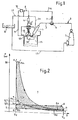
- FIG. 2 shows the working diagram (pV diagram) of a combined compression and extension brake cycle.
- the cylinder pressure is plotted on the ordinate and the stroke volume on the abscissa.
- V H means stroke volume and V K compression volume).
- the inlet valve E s closes and the compression takes place until the outlet valve 14 opens through the actuating piston 4 of the hydraulic system, as a rule before or possibly after the TDC (the latter with a small accelerator pedal pressure, ie not full delivery of the fuel quantity) (c , A ö1 ).
- the outlet opening pressure depends, among other things, on the compression ratio of the engine, on the start of delivery of the injection pump and on the possible boost pressure. Without considering a possible boost pressure, this pressure is set at approximately 30 bar in the exemplary embodiment when the fuel quantity is full.
- this point is approx. 15 to 30 ° KW before TDC.
- the pressure in the engine cylinder drops to the pressure determined by the valve 10 (e, A s1 ).
- the opening pressure of the valve 10 is suitably chosen so that it is slightly above the pressure in the exhaust pipe.
- the pressure here is between 3 and 4.5 bar due to the closed extension brake flap.
- the expansion begins at point e and continues until the exhaust valve is opened again by the normal charge exchange control (f).
- the final expansion pressure runs below atmospheric pressure.
- the charge change f - g - h - a - b is known to be characterized by a high back pressure.
- the high-pressure and low-pressure work surfaces formed by the changes in condition are negative, that is, they destroy work.
- the size of the negative high pressure working loop depends on the pressure built up behind the working cylinder (actuating cylinder 4). If the pressure is less than to open the outlet valve 14 immediately after the start of delivery, that is, for opening before TDC is necessary, the outlet valve 14 is opened after TDC during expansion with a decreasing pressure in the engine cylinder. This shortens the negative high pressure loop. It even becomes zero if the funding is canceled. It follows that with "accelerate" this work surface can theoretically be controlled according to the driving or braking conditions.
Landscapes
- Engineering & Computer Science (AREA)
- Mechanical Engineering (AREA)
- General Engineering & Computer Science (AREA)
- Chemical & Material Sciences (AREA)
- Combustion & Propulsion (AREA)
- Valve Device For Special Equipments (AREA)
- Output Control And Ontrol Of Special Type Engine (AREA)
Description
- Die Erfindung bezieht sich auf eine Motorbremse gemäß dem Oberbegriff des Anspruchs 1.
- Aus US-PS 41 50 640 ist eine Vorrichtung zur Ansteuerung von Auslaßventilen einer Brennkraftmaschine bekannt, bei der die Auslaßventile während des Motorbremsbetriebes im Bereich des Zünd-OT hydraulisch betätigbar einen kleinen Spalt offengehalten werden. Die hydraulische Betätigung besteht aus einem Geberzylinder mit Geberkolben und einem Betätigungszylinder mit Betätigungskolben, welcher auf das Auslaßventil wirkt. Der Geberkolben wird von einem Kipphebel betätigt, welcher gleichzeitig der Betätigung eines Pumpenkolbens einer Einspritzvorrichtung für Brennstoff dient. Der Kipphebel wird von einer relativ langen Stößelstange angetrieben, wobei sich die Bewegung der Stößelstange dem Kipphebel mitteilt, welcher in Fortsetzung der Bewegungsrichtung der Stößelstange zunächst den Geberkolben für die Ventilsteuerung antreibt und welcher auf der anderen Seite die Einspritzvorrichtung betätigt. Eine derartige Vorrichtung zur Steuerung der Auslaßventile im Motor-Bremsbetrieb erfordert eine zusätzliche Baueinheit, bestehend aus Geberzylinder und Geberkolben, was zu höheren Herstellungskosten führt und zusätzlich den Wartungsaufwand vergrößert. Die relativ schlanke Stößelstange erlaubt nicht die Übertragung großer Kräfte, wie sie für den hohen Einspritzdruck bei Dieselbrennkraftmaschinen notwendig sind. Eine derartige Einrichtung eignet sich nur für Niederdruck-Einspritzvorrichtungen an Otto-Motoren.
- Als Motorbremssystem ist die sogenannte Auspuffbremse bekannt. Durch das Schließen eines Absperrorgans im Auspuff wird die Ausschiebearbeit desKolbens dadurch erhöht, daß in den Auspuffrohren ein Gegendruck aufgebaut wird, gegen den der Kolben ausschieben muß.
- Aufgabe der Erfindung ist es deshalb, eine Motorbremse gemäß dem Gattungsbegriff des Patentanspruches 1 so weiterzubilden, daß sie wesentlich einfacher und damit billiger ausgestaltet ist, d. h. die möglichst ohne größere Konstruktionsänderung ausgeführt werden kann. Zudem soll diese problemlos mit der üblichen Auspuffbremse kombinierbar sein.
- Erfindungsgemäß wird diese Aufgabe durch die kennzeichnenden Merkmale des Patentanspruches 1 gelöst.
- Durch die Anwendung der Einspritzpumpe als Geberzylinder liegt eine sehr einfach ausgebildete hydraulische Vorrichtung vor, bei der die Anzahl der zusätzlichen Steuereinrichtungen bzw. Stellorgane gering ist. Auch können diese Stellorgane, beispielsweise der Betätigungskolben, wegen des Hochdrucks, kleiner ausgeführt werden.
- Vorteilhafte und förderliche Weiterbildungen der Erfindung lassen sich den Unteransprüchen 2 bis 8 entnehmen.
- Nachstehend wird anhand von Zeichnungen die Erfindung näher erläutert. Es zeigt:
- Figur 1
- eine schematische Darstellung des Motorbremssystems und
- Figur 2
- einen kombinierten Kompressions- und Ausschubbremszyklus, dargestellt in einem Arbeitsdiagramm.
- Die Figur 1 zeigt schematisch das Motorbremssystem (die Dekompressionsbremse) der Erfindung. Hierbei werden die Auslaßventile 14 eines direkt einspritzenden Dieselmotors (mit Motorzylinder 13, Motorkolben 15 sowie Kolbenbrennraum 16) nahe des oberen Totpunktes (im Bereich des Zünd-OT) des Kompressionshubes geringfügig geöffnet, so daß die durch den Motor während des Kompressionshubes absorbiete Energie nicht während des Expansionshubes an den Motor zurückgegeben wird.
- Die Öffnung des Auslaßventils 14 (bzw. der Auslaßventileinrichtungen) erfolgt über eine hydraulische Vorrichtung, welche aus einem das Auslaßventil 7 steuernden Betätigungszylinder mit Betätigungskolben 4 (wirkt auf den Daumen des Kipphebels) einer Steuerleitung 3a sowie einem Geberzylinder mit Geberkolben 1 besteht. Erfindugsgemäß wird die hydraulische Betätigung der Betätigungskolben 4 von den Einspritzpumpenelementen als Geberkolben 1 verursacht. Als Hydraulikfluid findet der Dieselkraftstoff Anwendung. Die Verwendung der motoreigenen Einspritzpumpe selbst als gesteuerter Geberzylinder 1 (Masterzylinder) ist deshalb so vorteilhaft, weil der Förderbeginn derselben vor dem Ende des Kompressionshubes bei 15 bis 30 ° KW vor OT liegt, wo eben das Öffnen des Auslaßventils 14 gewünscht wird.
- Der durch die Einspritzpumpe 1 erreichbare Förderdruck ist hoch, er reicht bis 1000 bar, und kann somit eine ausreichende Öffnungskraft auf das Auslaßventil 14 ausüben. Wegen des hohen Druckniveaus im Betätigungszylinder hat der Betätigungskolben 4 einen kleinen (ca. 10 mm) Durchmesser. Das Fördervolumen (Hubvolumen) pro Arbeitszyklus der Einspritzpumpe 1 reicht aus, dem Betätigungskolben 4 einen maximalen Hub von ca. 2,5 mm zu geben.
- In der zwischen Einspritzpumpe 1 und Einspritzdüse 5 vorliegenden Einspritzleitung 3 ist eine Weiche 6 angeordnet. Diese läßt im Motorbetrieb den Kraftstoff unbehindert zur Einspritzdüse 5 und im Bremsbetrieb zum Betätigungszylinder 4 strömen. In die Einspritzleitung 3 ist eine Weiche 6 eingebaut, von der die Steuerleitung 3a abzweigt. In dieser Steuerleitung 3a ist nach der Weiche 6 ein Rückschlagventil 7 vorgesehen. Dieses verhindert die Rückströmung des Kraftstoffes und somit keinerlei Störung in der Einspritzleitung 3. So bleibt das Auslaßventil 14 durch den Betätigungskolben 4 der Hydraulik geöffnet. Unter Umständen kann auch das einspritzpumpeneigene Rückschlagventil ausreichend sein.
- In einer Abzweigleitung 8 zurSteuerleitung 3a liegt ein Ventil 10 vor. Dieses wird vom Druck des Motorzylinders 13 über eine Druckleitung 9 beaufschlagt. Der Motor-Zylinderdruck kann durch ein zusätzliches Auspuffbremssystem (Auspuffklappe) beeinflußt werden, was die Bremsleistung verbessert.
- Das vom Druck des Motorzylinders 13 gesteuerte Ventil 10 läßt das Auslaßventil 7 schließen, wenn der Druck im Motorzylinder 13 unter einem bestimmten Pegel sinkt. Die Rückströmung des Kraftstoffs aus dem Arbeitszylinder 4 (über eine Abflußleitung 11) wird hierbei durch das Ventil 10 ebensolange verhindert. Das Schließen des Auslaßventils 7 wird beim Unterschreiten des gewünschten minimalen Ablase-Zylinderdrucks (im Ausführungsbeispiel bei ca. 5,7 bar) eingeleitet.
- Die Abflußleitung 11 (Leckleitung) des Ventils 10 ist an die Leckleitung 5a der Einspritzdüse 5 angeschlossen. Die Leckleitungen 5a, 11 führen zu einem Hydraulikfluid-Vorratsbehälter 12. Aus diesem wird auch über eine Leitung 17 die Einspritzpumpe 1 gespeist.
- In der Figur 2 ist das Arbeitsdiagramm (p-V-Diagramm) eines kombinierten Kompressions- und Ausschubbremszyklus dargestellt. Hierbei ist auf der Ordinate der Zylinderdruck und auf der Abszisse das Hubvolumen aufgetragen. (VH bedeutet hierbei Hubvolumen und VK Kompressionsvolumen).
- Nach dem Ansaugvorgang a-b schließt das Einlaßventil Es und die Kompression erfolgt, bis das Auslaßventil 14 durch den Betätigungskolben 4 der Hydraulik in der Regel vor oder eventuell auch nach dem OT (letzteres bei kleinem Gaspedaldruck, d. h. nicht voller Lieferung der Kraftstoffmenge) öffnet (c, Aö1). Der Auslaßöffnungsdruck hängt u. a. vom Verdichtungsverhältnis des Motors, vom Förderbeginn der Einspritzpumpe und vom eventuellen Ladedruck ab. Ohne die Berücksichtigung eines eventuellen Ladedrucks wird dieser Druck bei voller Kraftstoffmenge im Ausführungsbeispiel auf ca. 30 bar festgesetzt.
- Im Interesse einer akzeptablen Bremsleistung liegt dieser Punkt ca. 15 bis 30 ° KW vor OT. Nach dem Öffnen des Auslaßventils 14 fällt der Druck im Motor-Zylinder (Punkt d) bis auf den durch das Ventil 10 bestimmten Druck ab (e, As1). Der Öffnungsdruck des Ventils 10 ist zweckmäßig so gewählt, daß er wenig über dem Druck im Auspuffrohr liegt. Hier beträgt der Druck wegen der geschlossenen Ausschubbremsklappe zwischen 3 und 4,5 bar. Die Expansion fängt im Punkt e an und läuft bis zum wiederholten Öffnen des Auslaßventils durch die normale Ladungswechselsteuerung ab (f). Der Expansionsenddruck läuft bis unter Atmosphärendruck. Der Ladungswechsel f - g - h - a - b ist bekannterweise durch hohen Ausschubgegendruck charakterisiert.
- Wie ersichtlich sind die durch die Zustandsänderungen gebildeten Hoch- und Niederdruck-Arbeitsflächen negativ, also arbeitsvernichtend. Die Größe der negativen Hochdruck-Arbeitsschleife hängt vom aufgebauten Druck hinter dem Arbeitszylinder (Betätigungszylinder 4) ab. Wenn der Druck kleiner ist als zum Öffnen des Auslaßventils 14 gleich nach dem Förderbeginn, also für das Öffnen vor OT notwendig ist, wird das Auslaßventil 14 nach dem OT während der Expansion bei einem abnehmenden Druck im Motorzylinder geöffnet. Die negative Hochdruckschleife wird dadurch verkürzt. Sie wird sogar - bei abgestellter Förderung - Null. Es folgt daraus, daß mit "Gasgeben" diese Arbeitsfläche theoretisch dem Fahr- bzw. Bremsverhältnissen entsprechend gesteuert werden kann.
Claims (8)
- Motorbremse einer Dieselbrennkraftmaschine für Nutzfahrzeuge, bei der ein Auslaßventil 14 während des Motorbremsbetriebes mittels einer hydraulischen Vorrichtung im Bereich des Zünd-OT taktweise geöffnet werden kann, wobei die hydraulische Vorrichtung aus einem Geberzylinder mit Geberkolben und das Auslaßventil 14 steuernden Betätigungskolben mit Betätigungszylinder 4 gebildet wird, dadurch gekennzeichnet, daß eine Einspritzpumpe (1) der Dieselbrennkraftmaschine die Funktion von Geberzylinder und Geberkolben wahrnimmt, daß von einer Einspritzleitung (3) eine Steuerleitung (3a) abzweigt, und daß an der Abzweigstelle eine Weiche (6) vorgesehen ist, wobei die Weiche (6) derart regelbar ist, daß beim Motorbetrieb die Einspritzpumpe (1) mit einer Einspritzdüse (5) und beim Motor-Bremsbetrieb die Einspritzpumpe (1) mit dem Betätigungszylinder (4) verbindbar ist.
- Motorbremse nach Anspruch 1, dadurch gekennzeichnet, daß in der Steuerleitung 3a ein Rückschlagventil (7) angeordnet ist.
- Motorbremse nach Anspruch 2, dadurch gekennzeichnet, daß das am Ausgang der Einspritzpumpe (1) in der Regel vorgesehene Rückschlagventil Anwendung findet.
- Motorbremse nach Anspruch 2, dadurch gekennzeichnet, daß am Beginn der Steuerleitung 3a in der Nähe der Weiche (6) das Rückschlagventil (7) vorgesehen ist.
- Motorbremse nach Anspruch 1, dadurch gekennzeichnet, daß in einer Abzweigleitung (8) der Steuerleitung 3a ein vom Druck des Motorzylinders (13) - über eine Druckleitung 9 beaufschlagtes - gesteuertes Ventil (10) vorgesehen ist.
- Motorbremse nach Anspruch 5, dadurch gekennzeichnet, daß die Höhe des Motorzylinderdruckes d. h. des Steuerungsdruckes des Ventils (10), durch ein zusätzliches Auspuffbremssystem (Auspuffklappe) bestimmt wird.
- Motorbremse nach Anspruch 5, dadurch gekennzeichnet, daß vom Ventil (10) eine Abflußleitung (Leckleitung 11), welche an der Leckleitung (5a) der Einspritzdüse (5) angeschlossen ist, zu einem Hydraulikfluid-Vorratsbehälter (12) führt.
- Motorbremse nach Anspruch 1, dadurch gekennzeichnet, daß als Hydraulik-Steuerfluid Dieselkraftstoff verwendet wird.
Applications Claiming Priority (2)
| Application Number | Priority Date | Filing Date | Title |
|---|---|---|---|
| DE3904497 | 1989-02-15 | ||
| DE3904497A DE3904497C1 (de) | 1989-02-15 | 1989-02-15 |
Publications (2)
| Publication Number | Publication Date |
|---|---|
| EP0383088A1 EP0383088A1 (de) | 1990-08-22 |
| EP0383088B1 true EP0383088B1 (de) | 1993-05-26 |
Family
ID=6374111
Family Applications (1)
| Application Number | Title | Priority Date | Filing Date |
|---|---|---|---|
| EP90101744A Expired - Lifetime EP0383088B1 (de) | 1989-02-15 | 1990-01-29 | Motorbremse für Nutzfahrzeuge |
Country Status (6)
| Country | Link |
|---|---|
| US (1) | US5000146A (de) |
| EP (1) | EP0383088B1 (de) |
| JP (1) | JPH02233814A (de) |
| DE (2) | DE3904497C1 (de) |
| RU (1) | RU1828499C (de) |
| ZA (1) | ZA899937B (de) |
Families Citing this family (30)
| Publication number | Priority date | Publication date | Assignee | Title |
|---|---|---|---|---|
| DE3909822A1 (de) * | 1989-03-25 | 1990-09-27 | Bosch Gmbh Robert | Einrichtung zur betaetigung und steuerung der ventile einer brennkraftmaschine |
| US5215054A (en) * | 1990-10-22 | 1993-06-01 | Jenara Enterprises Ltd. | Valve control apparatus and method |
| DE59303199D1 (de) * | 1993-01-25 | 1996-08-14 | Steyr Nutzfahrzeuge | Motorbremse bei einer 4-Takt-Brennkraftmaschine eines Nutzfahrzeuges |
| DE59300956D1 (de) * | 1993-01-25 | 1995-12-21 | Steyr Nutzfahrzeuge | Motorbremse bei einer 4-Takt-Brennkraftmaschine eines Nutzfahrzeuges. |
| EP0608521B1 (de) * | 1993-01-25 | 1995-12-27 | Steyr Nutzfahrzeuge Ag | Motorbremse bei einer 4-Takt-Brennkraftmaschine eines Nutzfahrzeuges |
| DE4407585C2 (de) * | 1994-03-08 | 1996-09-19 | Mtu Friedrichshafen Gmbh | Variable Ventilsteuerung |
| DE4423657C2 (de) * | 1994-07-06 | 1997-10-02 | Daimler Benz Ag | Betätigungseinrichtung für ein Motorbremsventil einer Brennkraftmaschine |
| US5647318A (en) | 1994-07-29 | 1997-07-15 | Caterpillar Inc. | Engine compression braking apparatus and method |
| US5540201A (en) | 1994-07-29 | 1996-07-30 | Caterpillar Inc. | Engine compression braking apparatus and method |
| US5526784A (en) | 1994-08-04 | 1996-06-18 | Caterpillar Inc. | Simultaneous exhaust valve opening braking system |
| DE4433258C1 (de) | 1994-09-19 | 1996-03-07 | Daimler Benz Ag | Motorbremse für eine Dieselbrennkraftmaschine |
| US5713331A (en) * | 1994-12-21 | 1998-02-03 | Mannesmann Rexroth Gmbh | Injection and exhaust-brake system for an internal combustion engine having several cylinders |
| DE19514116A1 (de) * | 1995-04-14 | 1996-10-17 | Daimler Benz Ag | Vorrichtung zur Steuerung von in einem Zylinder einer Brennkraftmaschine komprimierter Luft |
| US5495838A (en) * | 1995-05-12 | 1996-03-05 | Caterpillar Inc. | Compression braking system |
| DE19528792C1 (de) * | 1995-08-04 | 1996-08-14 | Daimler Benz Ag | Motorbremse für eine Dieselbrennkraftmaschine |
| DE19600562C1 (de) * | 1996-01-09 | 1997-05-22 | Daimler Benz Ag | Direkteinspritzende Brennkraftmaschine |
| US5735242A (en) | 1996-04-17 | 1998-04-07 | Cummins Engine Company, Inc. | Fuel pressure activated engine compression braking system |
| US6104977A (en) * | 1997-06-04 | 2000-08-15 | Detroit Diesel Corporation | Method and system for engine control |
| US6085721A (en) * | 1998-04-03 | 2000-07-11 | Diesel Engine Retarders, Inc. | Bar engine brake |
| DE10024268B4 (de) * | 2000-05-17 | 2012-11-29 | Robert Bosch Gmbh | Vorrichtung zur Benzindirekteinspritzung in einer Kolbenbrennkraftmaschine |
| US20030037765A1 (en) | 2001-08-24 | 2003-02-27 | Shafer Scott F. | Linear control valve for controlling a fuel injector and engine compression release brake actuator and engine using same |
| US6854442B2 (en) * | 2002-12-02 | 2005-02-15 | Caterpillar Inc | Rotary valve for controlling a fuel injector and engine compression release brake actuator and engine using same |
| CN100549432C (zh) * | 2006-03-27 | 2009-10-14 | 曼B与W狄赛尔公司 | 共轨液压系统 |
| DE102007014248A1 (de) | 2007-03-24 | 2008-09-25 | Schaeffler Kg | Hubkolbenbrennkraftmaschine mit Motorbremseinrichtung |
| DE102007014250A1 (de) | 2007-03-24 | 2008-09-25 | Schaeffler Kg | Brennkraftmaschine mit Motorbremse |
| DE102007033424A1 (de) | 2007-07-18 | 2009-01-22 | Man Nutzfahrzeuge Ag | Selbstreinigendes Abgasnachbehandlungssystem |
| DE102007051302A1 (de) | 2007-10-26 | 2009-04-30 | Schaeffler Kg | Hubkolbenbrennkraftmaschine mit Motorbremse und zusätzlichem Öffnen eines Auslassventils |
| DE102007061005A1 (de) | 2007-12-18 | 2009-06-25 | Man Nutzfahrzeuge Ag | Verfahren zur Verbesserung der Hydrolyse eines Reduktionsmittels in einem Abgasnachbehandlungssystem |
| DE102008039504A1 (de) | 2008-08-23 | 2010-02-25 | Schaeffler Kg | Hubkolbenbrennkraftmaschine mit Motorbremseinrichtung und schaltbarem Leerhubelement |
| CN105386810A (zh) * | 2015-12-31 | 2016-03-09 | 潍柴动力股份有限公司 | 一种发动机制动系统 |
Family Cites Families (9)
| Publication number | Priority date | Publication date | Assignee | Title |
|---|---|---|---|---|
| US3367312A (en) * | 1966-01-28 | 1968-02-06 | White Motor Corp | Engine braking system |
| US3547087A (en) * | 1968-08-09 | 1970-12-15 | White Motor Corp | Engine valve control for braking operation |
| US4158348A (en) * | 1977-06-30 | 1979-06-19 | Mason Lloyd R | System for retarding engine speed |
| US4150640A (en) * | 1977-12-20 | 1979-04-24 | Cummins Engine Company, Inc. | Fluidic exhaust valve opening system for an engine compression brake |
| US4398510A (en) * | 1978-11-06 | 1983-08-16 | The Jacobs Manufacturing Company | Timing mechanism for engine brake |
| US4384558A (en) * | 1981-08-03 | 1983-05-24 | Cummins Engine Company, Inc. | Engine compression brake employing automatic lash adjustment |
| US4697558A (en) * | 1986-02-18 | 1987-10-06 | Meneely Vincent A | Compression relief engine brake |
| US4711210A (en) * | 1986-12-29 | 1987-12-08 | Cummins Engine Company, Inc. | Compression braking system for an internal combustion engine |
| US4741307A (en) * | 1987-02-17 | 1988-05-03 | Pacific Diesel Brave Co. | Apparatus and method for compression release retarding of an engine |
-
1989
- 1989-02-15 DE DE3904497A patent/DE3904497C1/de not_active Expired - Fee Related
- 1989-12-28 ZA ZA899937A patent/ZA899937B/xx unknown
-
1990
- 1990-01-29 EP EP90101744A patent/EP0383088B1/de not_active Expired - Lifetime
- 1990-01-29 DE DE9090101744T patent/DE59001521D1/de not_active Expired - Fee Related
- 1990-01-31 RU SU904742939A patent/RU1828499C/ru active
- 1990-02-09 JP JP2028613A patent/JPH02233814A/ja active Pending
- 1990-02-09 US US07/477,596 patent/US5000146A/en not_active Expired - Fee Related
Also Published As
| Publication number | Publication date |
|---|---|
| DE3904497C1 (de) | 1990-01-25 |
| DE59001521D1 (de) | 1993-07-01 |
| US5000146A (en) | 1991-03-19 |
| EP0383088A1 (de) | 1990-08-22 |
| ZA899937B (en) | 1990-11-28 |
| JPH02233814A (ja) | 1990-09-17 |
| RU1828499C (ru) | 1993-07-15 |
Similar Documents
| Publication | Publication Date | Title |
|---|---|---|
| EP0383088B1 (de) | Motorbremse für Nutzfahrzeuge | |
| DE19581047B4 (de) | Hydraulisch betätigte elektronisch gesteuerte Brennstoffeinspritzvorrichtung | |
| EP0840009B1 (de) | Hochdruckpumpe | |
| DE69116382T2 (de) | Verfahren zur fluessigkeitskonditionierung in einer elektronisch gesteuerten einspritzeinheit zum starten | |
| DE68910658T2 (de) | Hochdruckpumpe mit veränderlichem Abfluss. | |
| DE69115298T2 (de) | Verfahren zum Betrieb einer hydraulisch betätigten und elektronisch gesteuerten Einspritzeinheit. | |
| DE3779943T2 (de) | Kraftstoffeinspritzsteuervorrichtung. | |
| DE69718458T2 (de) | Vorrichtung und verfahren zur anwendung in verbrennungsmotoren | |
| DE4118237C2 (de) | Einspritzsystem für Brennkraftmaschinen | |
| DE60301093T2 (de) | Vorrichtung und Verfahren zur Steuerung eines Otto-Miller Motors | |
| DE19528792C1 (de) | Motorbremse für eine Dieselbrennkraftmaschine | |
| DE69103323T2 (de) | Ventilsteuervorrichtung für eine Brennkraftmaschine. | |
| DE19716750C2 (de) | Motorbremssystem für einen Verbrennungsmotor | |
| DE4407585C2 (de) | Variable Ventilsteuerung | |
| DE3382635T2 (de) | Verfahren und geraet fuer die genaue steuerung der kraftstoffeinspritzung in einer brennkraftmaschine. | |
| DE69114864T2 (de) | Betätigungs- und ventilanordnung für eine hydraulisch betätigte elektronisch gesteuerte einspritzeinheit. | |
| EP0281580B1 (de) | Brennstoffeinspritzvorrichttung für eine dieselbrennkraftmaschine | |
| DE2719668A1 (de) | Mehrzylinder-viertakt-dieselmotor | |
| DE2913909C2 (de) | ||
| EP0670424B1 (de) | Einspritzanlage für die Einspritzung eines Kraftstoffs und einer Zusatzflüssigkeit in die Brennräume einer Brennkraftmaschine | |
| EP1402174A1 (de) | Kraftstoffeinspritzeinrichtung für eine brennkraftmaschine | |
| EP1392965B1 (de) | Druckverstärker einer kraftstoffeinspritzeinrichtung | |
| DE10247224A1 (de) | Betätigungsventil zur Steuerung einer Brennstoffeinspritzvorrichtung und eines Drucklöseventils und Motor, der diese verwendet | |
| DE3008070C2 (de) | ||
| DE69817387T2 (de) | Brennkraftmaschine mit kompressorfunktion |
Legal Events
| Date | Code | Title | Description |
|---|---|---|---|
| PUAI | Public reference made under article 153(3) epc to a published international application that has entered the european phase |
Free format text: ORIGINAL CODE: 0009012 |
|
| AK | Designated contracting states |
Kind code of ref document: A1 Designated state(s): DE FR GB IT SE |
|
| 17P | Request for examination filed |
Effective date: 19900927 |
|
| 17Q | First examination report despatched |
Effective date: 19920120 |
|
| ITF | It: translation for a ep patent filed | ||
| GRAA | (expected) grant |
Free format text: ORIGINAL CODE: 0009210 |
|
| AK | Designated contracting states |
Kind code of ref document: B1 Designated state(s): DE FR GB IT SE |
|
| ET | Fr: translation filed | ||
| REF | Corresponds to: |
Ref document number: 59001521 Country of ref document: DE Date of ref document: 19930701 |
|
| GBT | Gb: translation of ep patent filed (gb section 77(6)(a)/1977) |
Effective date: 19930624 |
|
| PLBE | No opposition filed within time limit |
Free format text: ORIGINAL CODE: 0009261 |
|
| STAA | Information on the status of an ep patent application or granted ep patent |
Free format text: STATUS: NO OPPOSITION FILED WITHIN TIME LIMIT |
|
| 26N | No opposition filed | ||
| EAL | Se: european patent in force in sweden |
Ref document number: 90101744.2 |
|
| PGFP | Annual fee paid to national office [announced via postgrant information from national office to epo] |
Ref country code: SE Payment date: 19961209 Year of fee payment: 8 |
|
| PGFP | Annual fee paid to national office [announced via postgrant information from national office to epo] |
Ref country code: FR Payment date: 19961230 Year of fee payment: 8 |
|
| PGFP | Annual fee paid to national office [announced via postgrant information from national office to epo] |
Ref country code: GB Payment date: 19970120 Year of fee payment: 8 |
|
| PGFP | Annual fee paid to national office [announced via postgrant information from national office to epo] |
Ref country code: DE Payment date: 19970311 Year of fee payment: 8 |
|
| PG25 | Lapsed in a contracting state [announced via postgrant information from national office to epo] |
Ref country code: GB Free format text: LAPSE BECAUSE OF NON-PAYMENT OF DUE FEES Effective date: 19980129 |
|
| PG25 | Lapsed in a contracting state [announced via postgrant information from national office to epo] |
Ref country code: SE Free format text: LAPSE BECAUSE OF NON-PAYMENT OF DUE FEES Effective date: 19980130 |
|
| PG25 | Lapsed in a contracting state [announced via postgrant information from national office to epo] |
Ref country code: FR Free format text: THE PATENT HAS BEEN ANNULLED BY A DECISION OF A NATIONAL AUTHORITY Effective date: 19980131 |
|
| GBPC | Gb: european patent ceased through non-payment of renewal fee |
Effective date: 19980129 |
|
| PG25 | Lapsed in a contracting state [announced via postgrant information from national office to epo] |
Ref country code: DE Free format text: LAPSE BECAUSE OF NON-PAYMENT OF DUE FEES Effective date: 19981001 |
|
| EUG | Se: european patent has lapsed |
Ref document number: 90101744.2 |
|
| REG | Reference to a national code |
Ref country code: FR Ref legal event code: ST |
|
| PG25 | Lapsed in a contracting state [announced via postgrant information from national office to epo] |
Ref country code: IT Free format text: LAPSE BECAUSE OF NON-PAYMENT OF DUE FEES;WARNING: LAPSES OF ITALIAN PATENTS WITH EFFECTIVE DATE BEFORE 2007 MAY HAVE OCCURRED AT ANY TIME BEFORE 2007. THE CORRECT EFFECTIVE DATE MAY BE DIFFERENT FROM THE ONE RECORDED. Effective date: 20050129 |