EP0381663A1 - Porte - Google Patents
Porte Download PDFInfo
- Publication number
- EP0381663A1 EP0381663A1 EP90890017A EP90890017A EP0381663A1 EP 0381663 A1 EP0381663 A1 EP 0381663A1 EP 90890017 A EP90890017 A EP 90890017A EP 90890017 A EP90890017 A EP 90890017A EP 0381663 A1 EP0381663 A1 EP 0381663A1
- Authority
- EP
- European Patent Office
- Prior art keywords
- gate
- hinge
- hinges
- section
- door
- Prior art date
- Legal status (The legal status is an assumption and is not a legal conclusion. Google has not performed a legal analysis and makes no representation as to the accuracy of the status listed.)
- Withdrawn
Links
Images
Classifications
-
- E—FIXED CONSTRUCTIONS
- E06—DOORS, WINDOWS, SHUTTERS, OR ROLLER BLINDS IN GENERAL; LADDERS
- E06B—FIXED OR MOVABLE CLOSURES FOR OPENINGS IN BUILDINGS, VEHICLES, FENCES OR LIKE ENCLOSURES IN GENERAL, e.g. DOORS, WINDOWS, BLINDS, GATES
- E06B3/00—Window sashes, door leaves, or like elements for closing wall or like openings; Layout of fixed or moving closures, e.g. windows in wall or like openings; Features of rigidly-mounted outer frames relating to the mounting of wing frames
- E06B3/32—Arrangements of wings characterised by the manner of movement; Arrangements of movable wings in openings; Features of wings or frames relating solely to the manner of movement of the wing
- E06B3/48—Wings connected at their edges, e.g. foldable wings
- E06B3/485—Sectional doors
Definitions
- the invention relates to a door, in particular a sectional door, in which door sections are connected to one another via external hinges, a first door section having a cylinder-shaped curved or prismatic, polygonally angled, approximately forming a quarter sector, in the longitudinal direction continuous projection, which in a engages the second gate portion provided longitudinal recess, the outer boundary edge facing away from the hinges moves over the curved or polygonally angled outer surface of the projection of the first gate portion at a distance.
- the projection is provided directly on the one gate section, the arcuate curvature passing into the wall of the gate section via a step directed toward the interior of the gate section.
- the longitudinal recess on the second gate section is complementary to the formation of the edge of the first gate section.
- band-shaped hinge part which is connected to the second gate section carrying the recess must be relatively long and extend over a considerable area along the outer wall of the first gate section. If the gate is now opened, then it pivots band-shaped hinge part away from the wall of the first gate section, so that here there is the possibility that your finger gets into the space between the wall of the first gate section and the band of the hinge, which then when closing the door there is a risk of being crushed Fingers is given.
- the invention has for its object to provide a gate of the type mentioned, in which the risk of crushing is also switched off on the inside of the gate.
- this object is achieved in that the longitudinal recess of the second gate section on the hinge side is delimited by a wall leg extending into the area of the hinge axis. This avoids that in the area of the inner wall of the second gate section having the projection or on the upper edge of the second door section when opening the door such a gap that one can reach in due to carelessness.
- the opening gap between the door sections is largely covered by the wall leg, and it is also avoided that a band-shaped fastening part of the hinge is lifted off one of the walls, so that there is no possibility of a finger between the band-shaped hinge fastening part and the To reach the wall of the gate section.
- the hinges are combined to form a continuous hinge band, as a result of which the opening gap between the door sections is also completely covered from the inside.
- the longitudinal recess can be formed by a U-profile, which engages with its web the longitudinal narrow side of the associated gate section is attached.
- Such a design can thus be attached to existing and conventional gate sections, since these sections are generally delimited by flat surfaces.
- the projection engaging in the longitudinal recess can also be formed by a U-profile, the leg of which is turned away from the hinges is extended by a quarter-circle section of a circular cylinder wall.
- the U-profiles can be divided in the longitudinal direction, preferably in the central region of the webs.
- the two parts of the U-profiles can be connected by a heat-insulating body.
- the hinge-side wall leg of the second door section can be formed by the hinge support band pointing upwards.
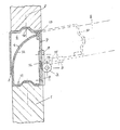
- first gate section 1 and 2 denote the two gate sections which are connected to one another via a hinge 3.
- a protrusion Provided on the first gate section 1 is a protrusion extending in the longitudinal direction thereof, which is delimited by a lateral surface 4 which forms approximately the quarter arc of a cylinder.
- the front outer edge 5 slides along this lateral surface Recess 6, which is provided on the second gate section and into which the projection delimited by the wall 4 engages.
- the recess 6 is formed in the illustrated embodiment by a U-profile, which is connected via its leg 10 to the second gate section.
- the hinge-side leg 7 of the U-profile extends into the area of the axis of the hinge 3.
- the connection of the gate sections 1, 2 is in the present case formed by a plurality of hinges 3, which, however, could also be combined to form a common hinge band.
- the projection having the wall 4 is formed in the illustrated embodiment by a further U-profile, which is attached to the first gate section.
- This U-profile is also fastened with its web to the longitudinal narrow side of the gate section 1, the leg of the U-profile 11 facing away from the hinges being extended by a circular-cylindrical part 12, the center of the curvature being in the axis of the hinges 3.
- Said projection can, likewise in a manner not shown, be formed by a solid body or by an appropriately designed extension which is integrally formed with the lower gate section.
- the wall 4 need not be curved in the shape of a circular arc. Any other curvature is possible in which the gap between the wall 4 and the leg 5 of the upper gate section 2 moved over it does not exceed the legally prescribed maximum value for a pinch joint. Under these Conditions, a prismatic, polygonally angled wall can also be used instead of a continuously curved wall 4.
- a seal 13 is provided on the top, to which the free end of the extension 12 of the U-profile 11 or a corresponding part of the differently shaped projection when the gate sections 1 are in the closed position , 2 comes to rest, whereby the door connection is sealed when the door is closed.
- the hinge 3 is fastened to the associated wall legs via its hinge support straps 8, 9.
- the wall leg 7 can be saved in a manner not shown if the hinge support band 8 is pulled up to the upper gate section 2, ie the hinge support band 8 thus forms the wall leg 7.
- the hinge-side leg of the U-profile 11 has at its free end an outwardly facing gradation into which the leg 7 of the U-profile forming the recess 6 engages with a complementary gradation when the door is closed.
- the two step-shaped parts are designated 14 and 15.
- the two webs of the U-profiles are themselves profiled, etc. trapezoidal, since the connection of the gate sections 1, 2 is shown on such conventional designs in which a sealing of the two gate sections against one another is achieved by the engagement of a trapezoidal projection of the one gate section in a trapezoidal cross-section groove of the other projection. If the longitudinal narrow sides of the gate sections 1, 2 are flat, it is of course also possible to use flat webs for the U-profiles.
- the U-profiles of both door sections 1, 2 can be divided in their longitudinal direction, preferably in the central region of the webs of the U-profiles, and connected by a heat-insulating body.
Landscapes
- Engineering & Computer Science (AREA)
- Civil Engineering (AREA)
- Structural Engineering (AREA)
- Gates (AREA)
Applications Claiming Priority (2)
| Application Number | Priority Date | Filing Date | Title |
|---|---|---|---|
| AT148/89 | 1989-01-26 | ||
| AT14889A AT390297B (de) | 1989-01-26 | 1989-01-26 | Tor |
Publications (1)
| Publication Number | Publication Date |
|---|---|
| EP0381663A1 true EP0381663A1 (fr) | 1990-08-08 |
Family
ID=3482810
Family Applications (1)
| Application Number | Title | Priority Date | Filing Date |
|---|---|---|---|
| EP90890017A Withdrawn EP0381663A1 (fr) | 1989-01-26 | 1990-01-25 | Porte |
Country Status (2)
| Country | Link |
|---|---|
| EP (1) | EP0381663A1 (fr) |
| AT (1) | AT390297B (fr) |
Cited By (5)
| Publication number | Priority date | Publication date | Assignee | Title |
|---|---|---|---|---|
| WO1997010405A1 (fr) * | 1995-09-13 | 1997-03-20 | Lindab A/S | Porte relevante |
| EP0787882A3 (fr) * | 1995-08-17 | 1998-05-13 | Lindpointner Tore Gesellschaft M.B.H. | Vantail de porte sectionnelle |
| NL1005166C2 (nl) * | 1997-02-03 | 1998-08-04 | Polynorm Nv | Werkwijze voor het verschaffen van een garagedeur. |
| EP0989275A3 (fr) * | 1998-09-21 | 2001-05-09 | Cardo Door Production A/S | Ensemble de charnière |
| GB2456144A (en) * | 2008-01-03 | 2009-07-08 | James Iain Stamp | Door hinge with integrated finger guard |
Families Citing this family (2)
| Publication number | Priority date | Publication date | Assignee | Title |
|---|---|---|---|---|
| DE4430744A1 (de) * | 1994-08-30 | 1996-03-14 | Erich Doering | Fingerschutz für Sektionaltore |
| DE19624764A1 (de) * | 1996-06-21 | 1998-01-08 | Braselmann Gudrun | Sektionaltor |
Citations (5)
| Publication number | Priority date | Publication date | Assignee | Title |
|---|---|---|---|---|
| DE216816C (fr) * | ||||
| US2557716A (en) * | 1945-12-07 | 1951-06-19 | Moynahan Bronze Company | Safety hinge |
| FR2458665A1 (fr) * | 1979-06-07 | 1981-01-02 | Kawneer Aluminium Gmbh | Porte avec protection pour les doigts dans la zone de la battee |
| DE3121900A1 (de) * | 1980-06-04 | 1982-06-16 | Verhoog's Handelsonderneming B.V., Zaandam | Abdeckung fuer den spalt zwischen falttuerfluegeln |
| AT382423B (de) * | 1985-07-03 | 1987-02-25 | Waldner Fa Felix | Hubgliedertor |
-
1989
- 1989-01-26 AT AT14889A patent/AT390297B/de not_active IP Right Cessation
-
1990
- 1990-01-25 EP EP90890017A patent/EP0381663A1/fr not_active Withdrawn
Patent Citations (5)
| Publication number | Priority date | Publication date | Assignee | Title |
|---|---|---|---|---|
| DE216816C (fr) * | ||||
| US2557716A (en) * | 1945-12-07 | 1951-06-19 | Moynahan Bronze Company | Safety hinge |
| FR2458665A1 (fr) * | 1979-06-07 | 1981-01-02 | Kawneer Aluminium Gmbh | Porte avec protection pour les doigts dans la zone de la battee |
| DE3121900A1 (de) * | 1980-06-04 | 1982-06-16 | Verhoog's Handelsonderneming B.V., Zaandam | Abdeckung fuer den spalt zwischen falttuerfluegeln |
| AT382423B (de) * | 1985-07-03 | 1987-02-25 | Waldner Fa Felix | Hubgliedertor |
Cited By (7)
| Publication number | Priority date | Publication date | Assignee | Title |
|---|---|---|---|---|
| EP0787882A3 (fr) * | 1995-08-17 | 1998-05-13 | Lindpointner Tore Gesellschaft M.B.H. | Vantail de porte sectionnelle |
| WO1997010405A1 (fr) * | 1995-09-13 | 1997-03-20 | Lindab A/S | Porte relevante |
| US5927369A (en) * | 1995-09-13 | 1999-07-27 | Lindab | Lift gate |
| NL1005166C2 (nl) * | 1997-02-03 | 1998-08-04 | Polynorm Nv | Werkwijze voor het verschaffen van een garagedeur. |
| EP0856632A1 (fr) * | 1997-02-03 | 1998-08-05 | Polynorm N.V. | Dispositif de sécurité anti-pince doigts pour portes de garage, ainsi que cette porte et son procédé de fabrication |
| EP0989275A3 (fr) * | 1998-09-21 | 2001-05-09 | Cardo Door Production A/S | Ensemble de charnière |
| GB2456144A (en) * | 2008-01-03 | 2009-07-08 | James Iain Stamp | Door hinge with integrated finger guard |
Also Published As
| Publication number | Publication date |
|---|---|
| ATA14889A (de) | 1989-09-15 |
| AT390297B (de) | 1990-04-10 |
Similar Documents
| Publication | Publication Date | Title |
|---|---|---|
| DE3816985A1 (de) | Sektionaltorblatt | |
| DE3532650A1 (de) | Moebelscharnier | |
| EP0381663A1 (fr) | Porte | |
| CH676376A5 (en) | Strip-type door-leaf seal | |
| EP0010763B1 (fr) | Profilé pour cadres de portes et de fenêtres ou pour des ensembles fonctionnels amovibles ou analogues d'armoires d'appareillage électrique ou analogues | |
| DE2753522A1 (de) | Moebelscharnier | |
| AT402087B (de) | Sektionaltorblatt | |
| DE19935988B4 (de) | Einbaukältegerät | |
| CH688102A5 (de) | Falt- oder Schwingfluegeltor. | |
| EP0338519A1 (fr) | Charnière à double joint pour la connection d'un panneau de porte à la paroi fixe d'un chassis de voiture utilitaire | |
| EP0561199B1 (fr) | Volets pour couvertures de piscines | |
| DE10211709C1 (de) | Duschkabine mit einer wenigstens eine Glasplatte aufweisenden Duschtrennwand | |
| DE3223590C2 (fr) | ||
| DE20109557U1 (de) | Innenscharnier insbesondere in einem Schaltgehäuse | |
| DE2907049A1 (de) | Elektrische einbaudose | |
| DE19617624A1 (de) | Feuerschutztür | |
| EP0213310B1 (fr) | Profilé extrudé en matière synthétique pour réfrigérateurs ou similaires | |
| DE2131852C3 (de) | Klappenscharnier | |
| DE2460943A1 (de) | Moebelscharnier | |
| DE3343775A1 (de) | Eckumlenkung eines in hinterschnittene profilnuten oder rahmenprofile von fenster und tueren aus metall, kunststoff o.dgl. einsetzbaren treibstangenverschluss | |
| DE19508482C2 (de) | Schrank, insbesondere für medizinische oder zahnmedizinische Arbeitsplätze | |
| DE3122875A1 (de) | "abdichtung von tueren an kraftfahrzeug-kofferaufbauten" | |
| EP1296014B1 (fr) | Porte sectionnelle | |
| DE2435720A1 (de) | Aufbaubares und zerlegbares moebelstueck | |
| DE4433160A1 (de) | Behälterverschluß mit Kindersicherung |
Legal Events
| Date | Code | Title | Description |
|---|---|---|---|
| PUAI | Public reference made under article 153(3) epc to a published international application that has entered the european phase |
Free format text: ORIGINAL CODE: 0009012 |
|
| AK | Designated contracting states |
Kind code of ref document: A1 Designated state(s): AT BE CH DE DK ES FR GB GR IT LI LU NL SE |
|
| STAA | Information on the status of an ep patent application or granted ep patent |
Free format text: STATUS: THE APPLICATION IS DEEMED TO BE WITHDRAWN |
|
| 18D | Application deemed to be withdrawn |
Effective date: 19910209 |