EP0380907A1 - Disjoncteur à haute et moyenne tension à gaz de soufflage - Google Patents
Disjoncteur à haute et moyenne tension à gaz de soufflage Download PDFInfo
- Publication number
- EP0380907A1 EP0380907A1 EP90100019A EP90100019A EP0380907A1 EP 0380907 A1 EP0380907 A1 EP 0380907A1 EP 90100019 A EP90100019 A EP 90100019A EP 90100019 A EP90100019 A EP 90100019A EP 0380907 A1 EP0380907 A1 EP 0380907A1
- Authority
- EP
- European Patent Office
- Prior art keywords
- piston
- circuit breaker
- tube
- arc
- cylinder
- Prior art date
- Legal status (The legal status is an assumption and is not a legal conclusion. Google has not performed a legal analysis and makes no representation as to the accuracy of the status listed.)
- Granted
Links
Images

Classifications
-
- H—ELECTRICITY
- H01—ELECTRIC ELEMENTS
- H01H—ELECTRIC SWITCHES; RELAYS; SELECTORS; EMERGENCY PROTECTIVE DEVICES
- H01H33/00—High-tension or heavy-current switches with arc-extinguishing or arc-preventing means
- H01H33/70—Switches with separate means for directing, obtaining, or increasing flow of arc-extinguishing fluid
- H01H33/88—Switches with separate means for directing, obtaining, or increasing flow of arc-extinguishing fluid the flow of arc-extinguishing fluid being produced or increased by movement of pistons or other pressure-producing parts
- H01H33/90—Switches with separate means for directing, obtaining, or increasing flow of arc-extinguishing fluid the flow of arc-extinguishing fluid being produced or increased by movement of pistons or other pressure-producing parts this movement being effected by or in conjunction with the contact-operating mechanism
- H01H33/901—Switches with separate means for directing, obtaining, or increasing flow of arc-extinguishing fluid the flow of arc-extinguishing fluid being produced or increased by movement of pistons or other pressure-producing parts this movement being effected by or in conjunction with the contact-operating mechanism making use of the energy of the arc or an auxiliary arc
- H01H33/903—Switches with separate means for directing, obtaining, or increasing flow of arc-extinguishing fluid the flow of arc-extinguishing fluid being produced or increased by movement of pistons or other pressure-producing parts this movement being effected by or in conjunction with the contact-operating mechanism making use of the energy of the arc or an auxiliary arc and assisting the operating mechanism
-
- H—ELECTRICITY
- H01—ELECTRIC ELEMENTS
- H01H—ELECTRIC SWITCHES; RELAYS; SELECTORS; EMERGENCY PROTECTIVE DEVICES
- H01H33/00—High-tension or heavy-current switches with arc-extinguishing or arc-preventing means
- H01H33/70—Switches with separate means for directing, obtaining, or increasing flow of arc-extinguishing fluid
- H01H33/88—Switches with separate means for directing, obtaining, or increasing flow of arc-extinguishing fluid the flow of arc-extinguishing fluid being produced or increased by movement of pistons or other pressure-producing parts
- H01H33/90—Switches with separate means for directing, obtaining, or increasing flow of arc-extinguishing fluid the flow of arc-extinguishing fluid being produced or increased by movement of pistons or other pressure-producing parts this movement being effected by or in conjunction with the contact-operating mechanism
- H01H2033/908—Switches with separate means for directing, obtaining, or increasing flow of arc-extinguishing fluid the flow of arc-extinguishing fluid being produced or increased by movement of pistons or other pressure-producing parts this movement being effected by or in conjunction with the contact-operating mechanism using valves for regulating communication between, e.g. arc space, hot volume, compression volume, surrounding volume
Definitions
- the present invention relates to a high voltage circuit breaker of the dielectric gas type, such as sulfur hexafluoride, under a pressure of a few bars.
- the invention relates more particularly to a circuit breaker of the aforementioned type in which the increase in pressure due, at the time of tripping, to the appearance of an electric arc between the arcing contacts, is used to exert a motor force on the moving part; this arrangement, known for example from French patent 85 00610 filed on January 16, 1985 and published on July 18, 1986 under the number 2 576 142, makes it possible to cut the arc without requiring the use of a device too much power.
- An object of the invention is to provide a circuit breaker in which the pressure is rapidly transmitted to the piston linked to the operating member and in which the flow of gas from the arc zone takes place quickly and without disturbance.
- the subject of the invention is a high-voltage blow-out circuit breaker, comprising a cylindrical insulating jacket filled with dielectric gas under pressure, a fixed main contact, a fixed arcing contact and a movable assembly connected to a member.
- operating mechanism comprising a movable main contact, a movable arcing contact and a blowing cylinder associated with a blowing nozzle and cooperating with a first piston, a second piston integral with the movable assembly and sliding in a second fixed cylinder, characterized in that the second piston has a large cross-section with respect to the cross-section of the blowing cylinder, said second piston being associated with means of communication with low pressure drops with the arc zone, said second piston being pierced with calibrated orifices to limit the pressure on the face of said piston receiving the gases heated by the arc.
- the arcing contact consists of a first end of a metal tube coaxial with the circuit breaker, the second end of said tube being connected to said operating member, said second piston is an annular piston external to said tube and secured thereof, said means for establishing communication with low pressure drops being constituted by said tube pierced with large openings at its periphery, the inside of said tube being closed substantially in line with said piston by a part.
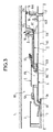
- the circuit breaker shown in partial view in FIG. 1 comprises an envelope 1, made of insulating material such as ceramic, of generally cylindrical shape with axis XX and delimiting an interior volume Vo filled with dielectric gas such as sulfur hexafluoride, under a pressure of a few bars.
- envelope 1 made of insulating material such as ceramic, of generally cylindrical shape with axis XX and delimiting an interior volume Vo filled with dielectric gas such as sulfur hexafluoride, under a pressure of a few bars.
- the circuit breaker comprises a fixed main contact 2 connected to a first outlet not shown, and a fixed arcing contact 3, having one end 3A made of resistant alloy to the effects of the arc, such as a tungsten alloy.
- the mobile assembly of the circuit breaker comprises a tube 4, one end of which 4A, made of an arc-resistant alloy, constitutes the movable arcing contact.
- the tube 4 is connected, at its other end 4B, to an operating device, not shown.
- the tube 4 is integral with a tube 5, one end of which 5A constitutes the movable main contact of the circuit breaker.
- an insulating nozzle 6 At the end 5A is fixed an insulating nozzle 6, the neck of which is obstructed by the arcing contact 4 when the circuit breaker is in the closed position.
- Holes 7 are made in the crown connecting the tubes 4 and 5 so that these tubes define a single and same volume V1, closed on one side by the nozzle 6.
- the tube 5 is guided by a first tubular part 8A of a fixed metal part 8 having a second tubular part 8B of diameter much greater than that of the part 8A.
- the part 8 is connected to a second outlet not shown.
- the tube 5 carries a sliding electrical contact 5C cooperating with the tube 8A.
- the connection between the tubes 8A and 8B is made by a massive portion of the part 8 in which are made openings in the form of radial chimneys 10. These chimneys are normally closed by a slide 11 of which an annular end 11A cooperates with a circular joint 8C at the base of the chimneys. The end 11A also serves to limit the stroke of the slide coming into abutment on the base of the chimneys opposite the joint 8C.
- the slide 11A has the general shape of a tube; it is integral with a tubular portion 11B which can slide on the tube 4 which serves as a guide.
- a seal is ensured by a seal 12.
- the slide 11 is also guided by the fixed part 8A which has an appropriate boss 8D.
- the annular space between the tubes 11 and 11B can be closed by an annular valve 13 whose stroke is limited by a projection 11C of the part 11B.
- the piston 15 defines with the tubes 8A and 8B a volume V2.
- the piston has openings 14A which can be closed by an annular valve 16, the stroke of which is limited by a projection 14B.
- the cross section of the piston is large with respect to the cross section of the blowing cylinder, for example the diameter ratio is at least equal to 2.
- the piston 14 also has calibrated openings 14C whose role will be explained below.
- the tube 4 is pierced with very large openings 15 on its surface in communication by large passages, the volume V2 with the volume V3 inside the tube 5. It is noted that the volume V3 is closed, on the operating member side by a disc 17 secured to the tube 4.
- the circuit breaker works as follows:
- the circuit breaker operating device drives the moving assembly (tubes 4 and 5, nozzle 6, piston 14) to the right of the figure.
- the main contacts separate and the current then flows through the arcing contacts 3 and 4.
- an arc 20 (fig.2) is formed; it strongly heats the surrounding gas and the pressure increases strongly.
- the volume V1 is closed by application of the valve 13.
- the hot gas escapes through the volume V3 surrounding the axis and passes through the openings 15 in the volume V2.
- the pressure prevailing in the volume V1 produces at the first zero crossing of the current an expansion of gas through the nozzle 6, which produces the extinction of the arc.
- the pressure in the volume V1 is sufficient to press the valve 13 against its seat; the expansion of volume V1 at zero current crossing is enough to cut the arc.
- the operating member moves the moving assembly to the right of the figure.
- a slight overpressure in the volume V2 causes the valve 16 to close on the one hand, and on the other hand, combined with a slight depression in the volume V1, causes the slide 1 to move to the left.
- the valve 13 opens, which allows filling of the volume V1 without requiring any particular effect due to a vacuum important in volume V1.
- the invention applies to high and medium voltage circuit breakers.
Landscapes
- Circuit Breakers (AREA)
- Superconductors And Manufacturing Methods Therefor (AREA)
- Pens And Brushes (AREA)
- Gas-Insulated Switchgears (AREA)
- Emergency Protection Circuit Devices (AREA)
- Organic Insulating Materials (AREA)
Abstract
Description
- La présente invention concerne un disjoncteur à haute tension du type à gaz diélectrique, tel que l'hexafluorure de soufre, sous une pression de quelques bars.
- L'invention vise plus particulièrement un disjoncteur du type précité dans lequel l'augmentation de pression due, au moment du déclenchement, à l'apparition d'un arc électrique entre les contacts d'arc, est mise à profit pour exercer un effort moteur sur l'équipage mobile ; cette disposition, connue par exemple par le brevet français 85 00610 déposé le 16 janvier 1985 et publié le 18 juillet 1986 sous le n° 2 576 142, permet d'assurer la coupure de l'arc sans nécessiter l'emploi d'un dispositif de manoeuvre de puissance trop importante.
- Dans ces disjoncteurs dits à faible énergie de manoeuvre, l'augmentation de pression qui naît au voisinage de l'arc se propage jusqu'à un piston lié à l'équipage mobile.
- La facilité et la rapidité avec lesquelles se propage la pression dépendent d'une part des obstables mis au passage du gaz entre la zone d'arc et le piston, d'autre part à l'évolution du gradient de pression entre la zone d'arc et la face du piston.
- Dans les dispositifs connus comme par exemple dans la demande de brevet allemand publiée DE 31 32825 A1 ou dans le brevet américain 2 957 063, la gaz se propage dans des conduits annulaires dont la section étroite n'est pas favorable à un écoulement rapide ; par ailleurs, le gradient de pression entre la zone d'arc et la face du piston diminue très vite, de sorte que l'action mécanique du gaz est très vite ralentie après l'apparition de l'arc.
- Un but de l'invention est de réaliser un disjoncteur dans lequel la pression est rapidement transmise au piston lié à l'organe de manoeuvre et dans lequel l'écoulement du gaz depuis la zone d'arc s'effectue rapidement et sans perturbation.
- L'invention a pour objet un disjoncteur à haute tension à gaz de soufflage, comprenant une enveloppe isolante cylindrique remplie de gaz diélectrique sous pression, un contact principal fixe, un contact d'arc fixe et un équipage mobile relié à un organe de manoeuvre comprenant un contact principal mobile, un contact d'arc mobile et un cylindre de soufflage associé à une buse de soufflage et coopérant avec un premier piston, un second piston solidaire de l'équipage mobile et coulissant dans un second cylindre fixe, caractérisé en ce que le second piston présente une section grande vis-à-vis de la section du cylindre de soufflage, ledit second piston étant associé à des moyens de mise en communication à faibles pertes de charge avec la zone d'arc, ledit second piston étant percé d'orifices calibrés pour limiter la pression sur la face dudit piston recevant les gaz chauffés par l'arc.
- Dans un mode préféré de réalisation le contact d'arc est constitué par une première extrémité d'un tube métallique coaxial au disjoncteur, la seconde extrémité dudit tube étant reliée audit organe de manoeuvre, ledit second piston est un piston annulaire extérieur audit tube et solidaire de celui-ci, lesdits moyens de mise en communication à faibles pertes de charge étant constitués par ledit tube percé de larges ouvertures à sa périphérie, l'intérieur dudit tube étant fermé sensiblement au droit dudit piston par une pièce.
- L'invention est expliquée maintenant en référence au dessin annexé dans lequel :
- - la figure 1 est une vue partielle en demi-coupe axiale d'un disjoncteur selon l'invention, représenté en position fermé,
- - la figure 2 est une vue partielle en demi-coupe axiale du même disjoncteur, représenté en cours d'ouverture (déclenchement),
- - la figure 3 est une vue partielle en demi-coupe axiale du même disjoncteur, en cours de fermeture (enclenchement).
- Le disjoncteur représenté en vue partielle dans la figure 1, comporte une enveloppe 1, en matériau isolant tel que la céramique, de forme générale cylindrique d'axe XX et délimitant un volume intérieur Vo rempli de gaz diélectrique tel que l'hexafluorure de soufre, sous une pression de quelques bars.
- Le disjoncteur comprend un contact principal fixe 2 relié à une première prise de courant non représentée, et un contact d'arc fixe 3, ayant une extrémité 3A réalisé en alliage résistant aux effets de l'arc, tel qu'un alliage de tungstène.
- L'équipage mobile du disjoncteur comprend un tube 4, dont une extrémité 4A, en alliage résistant à l'arc, constitue le contact d'arc mobile. Le tube 4 est relié, à son autre extrémité 4B, à un dispositif de manoeuvre non représenté. Le tube 4 est solidaire d'un tube 5 dont une extrémité 5A constitue le contact principal mobile de disjoncteur.
- A l'extrémité 5A est fixée une buse isolante 6 dont le col est obstrué par le contact d'arc 4 lorsque le disjoncteur est en position fermée.
- Des trous 7 sont pratiqués dans la couronne reliant les tubes 4 et 5 de telle sorte que ces tubes définissent un seul et même volume V1, fermé d'un côté par la buse 6.
- Le tube 5 est guidé par une première partie tubulaire 8A d'une pièce métallique fixe 8 ayant une seconde partie tubulaire 8B de diamètre bien supérieur à celui de la partie 8A.
- La pièce 8 est reliée à une seconde prise de courant non représentée.
- Le tube 5 porte un contact électrique glissant 5C coopérant avec le tube 8A.
- En position enclenchée du disjoncteur le courant circule par les pièces 2, 5, 8. Un joint 9 assure l'étanchéité entre tube 5 et tube 8A.
- La liaison entre les tubes 8A et 8B se fait par une portion massive de la pièce 8 dans laquelle sont pratiquées des ouvertures en forme de cheminées radiales 10. Ces cheminées sont normalement fermées par un coulisseau 11 dont une extrémité annulaire 11A coopère avec un joint circulaire 8C à la base des cheminées. L'extrémité 11A sert également à limiter la course du coulisseau en venant en butée sur la base des cheminées à l'opposé du joint 8C. Le coulisseau 11A a la forme générale d'un tube ; il est solidaire d'une portion tubulaire 11B pouvant glisser sur le tube 4 qui lui sert de guide.
- Une étanchéité est assurée par un joint 12. Le coulisseau 11 est également guidé par la pièce fixe 8A qui présente un bossage 8D approprié.
- L'espace annulaire entre les tubes 11 et 11B peut être fermé par un clapet annulaire 13 dont la course est limitée par un ressaut 11C de la pièce 11B.
- Le tube 5, qui constitue le cylindre de soufflage du disjoncteur, est solidaire d'un piston 14 placé à l'intérieur du tube 8B et pouvant coulisser dans ce tube de manière étanche grâce à un joint 14D. Le piston 15 délimite avec les tubes 8A et 8B un volume V2. Le piston possède des ouvertures 14A pouvant être fermées par un clapet annulaire 16, dont la course est limité par un ressaut 14B.
- Selon une caractéristique fondamentale de l'invention, la section du piston est grande vis-à-vis de la section du cylindre de soufflage, par exemple le rapport des diamètres est au moins égal à 2.
- Le piston 14 possède également des ouvertures calibrées 14C dont le rôle sera expliqué plus loin.
- Le tube 4 est percé de très larges ouvertures 15 sur sa surface en communication par de vastes passages le volume V2 avec le volume V3 intérieur au tube 5. On note que le volume V3 est fermé, côté organe de manoeuvre par un disque 17 solidaire du tube 4.
- Le fonctionnement du disjoncteur est le suivant :
- A la détection du court-circuit, le dispositif de manoeuvre du disjoncteur entraîne l'équipage mobile (tubes 4 et 5, buse 6, piston 14) vers la droite de la figure.
- Les contacts principaux se séparent et le courant traverse alors les contacts d'arc 3 et 4.
- A la séparation des contacts d'arc, un arc 20 (fig.2) se forme ; il échauffe fortement le gaz environnant et la pression croît fortement. Le volume V1 se ferme par application du clapet 13. Le gaz chaud s'échappe par le volume V3 entourant l'axe et passe par les ouvertures 15 dans le volume V2.
- La surface du piston étant très grande, la force exercée sur ce dernier, qui aide à la manoeuvre d'ouverture est importante.
- L'écoulement du gaz chaud provenant de la zone d'arc est facilité :
- a) par les grandes ouvertures 15 qui réduisent à néant les pertes de charge
- b) par les orifices calibrés 14C qui limitent la valeur de la pression dans le volume V2, assurant ainsi un gradient de pression entre la zone d'arc et la zone du piston 14.
- La pression régnant dans le volume V1 produit au premier passage par zéro du courant une détente de gaz à travers la buse 6, qui produit l'extinction de l'arc.
- A la séparation des contacts d'arc, l'augmentation de pression due à l'arc est insuffisante pour plaquer le clapet 16 sur son siège. Celui-ci reste ouvert, ce qui évite, dans le volume V2, toute dépression que viendrait freiner l'équipage mobile.
- La pression dans le volume V1 est suffisante pour plaquer le clapet 13 contre son siège ; la détente du volume V1 au passage par zéro du courant suffit à couper l'arc.
- On se référera à la figure 3.
- L'organe de manoeuvre déplace l'équipage mobile vers la droite de la figure. Une légère surpression dans le volume V2 provoque d'une part le fermeture du clapet 16, et d'autre part, combinée à une légère dépression dans le volume V1, provoque un déplacement vers la gauche du coulisseau 1.
- Ce dernier dégage la base des cheminées 10, ce qui permet au gaz du volume V2 de s'échapper vers le volume Vo et d'éviter une perte d'énergie par compression de gaz.
- Le clapet 13 s'ouvre, ce qui permet un remplissage du volume V1 sans nécessiter d'effet particulier en raison d'une dépression importante dans le volume V1.
- Le disjoncteur qui vient d'être décrit présente une énergie de manoeuvre très réduite par rapport aux disjoncteurs de l'art antérieur
- L'invention s'applique aux disjoncteurs à haute et moyenne tension.
Claims (5)
Priority Applications (1)
| Application Number | Priority Date | Filing Date | Title |
|---|---|---|---|
| AT90100019T ATE102741T1 (de) | 1989-01-02 | 1990-01-02 | Druckgasschalter fuer hoch- und mittelspannung. |
Applications Claiming Priority (2)
| Application Number | Priority Date | Filing Date | Title |
|---|---|---|---|
| FR8900009A FR2641409B1 (fr) | 1989-01-02 | 1989-01-02 | Disjoncteur a haute et moyenne tension a gaz de soufflage |
| FR8900009 | 1989-01-02 |
Publications (3)
| Publication Number | Publication Date |
|---|---|
| EP0380907A1 true EP0380907A1 (fr) | 1990-08-08 |
| EP0380907B1 EP0380907B1 (fr) | 1994-03-09 |
| EP0380907B2 EP0380907B2 (fr) | 1996-12-11 |
Family
ID=9377438
Family Applications (1)
| Application Number | Title | Priority Date | Filing Date |
|---|---|---|---|
| EP90100019A Expired - Lifetime EP0380907B2 (fr) | 1989-01-02 | 1990-01-02 | Disjoncteur à haute et moyenne tension à gaz de soufflage |
Country Status (9)
| Country | Link |
|---|---|
| US (1) | US4983789A (fr) |
| EP (1) | EP0380907B2 (fr) |
| JP (1) | JP2655733B2 (fr) |
| CN (1) | CN1016548B (fr) |
| AT (1) | ATE102741T1 (fr) |
| BR (1) | BR9000007A (fr) |
| CA (1) | CA2006934C (fr) |
| DE (1) | DE69007136T3 (fr) |
| FR (1) | FR2641409B1 (fr) |
Cited By (4)
| Publication number | Priority date | Publication date | Assignee | Title |
|---|---|---|---|---|
| EP0508160A2 (fr) * | 1991-04-12 | 1992-10-14 | GEC Alsthom T&D AG | Interrupteur à gaz comprimé |
| FR2679696A1 (fr) * | 1991-07-24 | 1993-01-29 | Alsthom Gec | Disjoncteur a haute et moyenne tension a gaz de soufflage. |
| EP0554686A1 (fr) * | 1992-02-06 | 1993-08-11 | GEC Alsthom T&D AG | Interrupteur à gaz sous pression |
| WO2016097258A1 (fr) * | 2014-12-19 | 2016-06-23 | General Electric Technology Gmbh | Disjoncteur comprenant un capot d'echappement de gaz a ouverture obturable |
Families Citing this family (7)
| Publication number | Priority date | Publication date | Assignee | Title |
|---|---|---|---|---|
| EP1403891B2 (fr) † | 2002-09-24 | 2016-09-28 | ABB Schweiz AG | Disjoncteur |
| DE102007031948A1 (de) * | 2007-07-06 | 2009-01-08 | Siemens Ag | Schaltgeräteanordnung mit einem Abströmkanal |
| JP5482613B2 (ja) * | 2010-10-05 | 2014-05-07 | 株式会社日立製作所 | ガス遮断器 |
| US9384924B2 (en) | 2012-05-22 | 2016-07-05 | Mitsubishi Electric Corporation | Gas circuit breaker |
| CN106328430B (zh) * | 2016-08-25 | 2018-08-07 | 中国西电电气股份有限公司 | 一种串联压气室的灭弧室 |
| JP6818604B2 (ja) * | 2017-03-24 | 2021-01-20 | 株式会社日立製作所 | ガス遮断器 |
| KR102466070B1 (ko) * | 2017-07-31 | 2022-11-10 | 제네럴 일렉트릭 테크놀러지 게엠베하 | 아크 블라스팅 유닛을 구비한 전기 스위치 |
Citations (3)
| Publication number | Priority date | Publication date | Assignee | Title |
|---|---|---|---|---|
| US2957063A (en) * | 1958-03-07 | 1960-10-18 | Westinghouse Electric Corp | Pumped-gas circuit interrupter |
| DE3132825A1 (de) * | 1981-06-18 | 1983-01-13 | Sprecher & Schuh AG, 5001 Aarau, Aargau | Druckgasschalter |
| FR2576142A1 (fr) * | 1985-01-16 | 1986-07-18 | Alsthom Atlantique | Disjoncteur a haute tension, a gaz comprime, a energie de manoeuvre assistee par l'effet thermique de l'arc |
Family Cites Families (7)
| Publication number | Priority date | Publication date | Assignee | Title |
|---|---|---|---|---|
| JPS5419054B2 (fr) * | 1973-11-07 | 1979-07-12 | ||
| CH600538A5 (fr) * | 1976-04-22 | 1978-06-15 | Bbc Brown Boveri & Cie | |
| JPS5372176A (en) * | 1976-12-10 | 1978-06-27 | Hitachi Ltd | Buffer type gas breaker |
| FR2576144B1 (fr) * | 1985-01-16 | 1987-02-06 | Alsthom Atlantique | Disjoncteur a haute tension, a gaz comprime, a faible energie de manoeuvre |
| FR2596575B1 (fr) * | 1986-03-26 | 1988-05-20 | Alsthom | Disjoncteur a gaz dielectrique sous pression |
| FR2596574B1 (fr) * | 1986-04-01 | 1988-05-20 | Alsthom | Disjoncteur a haute tension a gaz dielectrique sous pression |
| JP2528100B2 (ja) * | 1986-07-08 | 1996-08-28 | 株式会社日立製作所 | パツフア形ガス遮断器 |
-
1989
- 1989-01-02 FR FR8900009A patent/FR2641409B1/fr not_active Expired - Fee Related
- 1989-12-28 JP JP1345125A patent/JP2655733B2/ja not_active Expired - Fee Related
- 1989-12-29 CA CA002006934A patent/CA2006934C/fr not_active Expired - Fee Related
- 1989-12-31 CN CN89109654A patent/CN1016548B/zh not_active Expired
-
1990
- 1990-01-02 EP EP90100019A patent/EP0380907B2/fr not_active Expired - Lifetime
- 1990-01-02 AT AT90100019T patent/ATE102741T1/de not_active IP Right Cessation
- 1990-01-02 BR BR909000007A patent/BR9000007A/pt not_active IP Right Cessation
- 1990-01-02 US US07/459,893 patent/US4983789A/en not_active Expired - Lifetime
- 1990-01-02 DE DE69007136T patent/DE69007136T3/de not_active Expired - Fee Related
Patent Citations (3)
| Publication number | Priority date | Publication date | Assignee | Title |
|---|---|---|---|---|
| US2957063A (en) * | 1958-03-07 | 1960-10-18 | Westinghouse Electric Corp | Pumped-gas circuit interrupter |
| DE3132825A1 (de) * | 1981-06-18 | 1983-01-13 | Sprecher & Schuh AG, 5001 Aarau, Aargau | Druckgasschalter |
| FR2576142A1 (fr) * | 1985-01-16 | 1986-07-18 | Alsthom Atlantique | Disjoncteur a haute tension, a gaz comprime, a energie de manoeuvre assistee par l'effet thermique de l'arc |
Cited By (9)
| Publication number | Priority date | Publication date | Assignee | Title |
|---|---|---|---|---|
| EP0508160A2 (fr) * | 1991-04-12 | 1992-10-14 | GEC Alsthom T&D AG | Interrupteur à gaz comprimé |
| EP0508160A3 (en) * | 1991-04-12 | 1993-02-24 | Sprecher Energie Ag | Gas blast circuit breaker |
| FR2679696A1 (fr) * | 1991-07-24 | 1993-01-29 | Alsthom Gec | Disjoncteur a haute et moyenne tension a gaz de soufflage. |
| EP0526296A1 (fr) * | 1991-07-24 | 1993-02-03 | Gec Alsthom Sa | Disjoncteur à haute et moyenne tension à gaz de soufflage |
| US5258589A (en) * | 1991-07-24 | 1993-11-02 | Gec Alsthom Sa | High- and medium-voltage circuit breaker with lower operating energy |
| EP0554686A1 (fr) * | 1992-02-06 | 1993-08-11 | GEC Alsthom T&D AG | Interrupteur à gaz sous pression |
| WO2016097258A1 (fr) * | 2014-12-19 | 2016-06-23 | General Electric Technology Gmbh | Disjoncteur comprenant un capot d'echappement de gaz a ouverture obturable |
| FR3030869A1 (fr) * | 2014-12-19 | 2016-06-24 | Alstom Technology Ltd | Disjoncteur comprenant un capot d'echappement de gaz a ouverture obturable |
| US10262813B2 (en) | 2014-12-19 | 2019-04-16 | General Electric Technology Gmbh | Circuit breaker containing a gas escape hood with sealable opening |
Also Published As
| Publication number | Publication date |
|---|---|
| CN1016548B (zh) | 1992-05-06 |
| CA2006934C (fr) | 1994-04-26 |
| FR2641409B1 (fr) | 1996-04-26 |
| EP0380907B2 (fr) | 1996-12-11 |
| CN1044008A (zh) | 1990-07-18 |
| CA2006934A1 (fr) | 1990-07-02 |
| ATE102741T1 (de) | 1994-03-15 |
| US4983789A (en) | 1991-01-08 |
| EP0380907B1 (fr) | 1994-03-09 |
| DE69007136D1 (de) | 1994-04-14 |
| BR9000007A (pt) | 1990-10-09 |
| FR2641409A1 (fr) | 1990-07-06 |
| JP2655733B2 (ja) | 1997-09-24 |
| DE69007136T2 (de) | 1994-06-16 |
| DE69007136T3 (de) | 1997-03-06 |
| JPH02230625A (ja) | 1990-09-13 |
Similar Documents
| Publication | Publication Date | Title |
|---|---|---|
| EP0380907B2 (fr) | Disjoncteur à haute et moyenne tension à gaz de soufflage | |
| EP0591039B1 (fr) | Disjoncteur à haute tension à auto-soufflage ayant une chambre de coupure à compression de gaz réduite | |
| EP0441292B1 (fr) | Disjoncteur à moyenne ou haute tension à autosoufflage | |
| CA2074893C (fr) | Disjoncteur a moyenne ou haute tension a contacts d'arc en bout | |
| EP0367072B1 (fr) | Disjoncteur à haute tension à gaz diélectrique sous pression | |
| FR2576144A1 (fr) | Disjoncteur a haute tension, a gaz comprime, a faible energie de manoeuvre | |
| CA2014512C (fr) | Disjoncteur a moyenne tension a gaz de soufflage | |
| EP0359224B1 (fr) | Disjoncteur à haute tension à gaz diélectrique utilisé pour le soufflage | |
| EP0334181B1 (fr) | Disjoncteur à haute tension à faible énergie de manoeuvre | |
| EP0415098B1 (fr) | Disjoncteur à moyennne tension à autosoufflage | |
| EP0759629B1 (fr) | Disjoncteur muni d'une résistance de fermeture avec dispositif d'insertion | |
| EP0398211A1 (fr) | Disjoncteur à haute tension à gaz diélectrique de soufflage | |
| CA2017127C (fr) | Disjoncteur a moyenne tension a courant nominal eleve | |
| EP0406794B1 (fr) | Disjoncteur à haute ou moyenne tension | |
| EP0456025B1 (fr) | Disjoncteur à haute tension à arc série | |
| EP0400523B1 (fr) | Disjoncteur à haute tension à gaz dielectrique de soufflage | |
| FR2535518A1 (fr) | Chambre de coupure pour disjoncteur a gaz | |
| EP0398116B1 (fr) | Disjoncteur à moyenne tension à autosoufflage | |
| FR2705494A1 (fr) | Disjoncteur à manÓoeuvre assistée par voie électrodynamique. | |
| FR2729788A1 (fr) | Disjoncteur a haute tension a gaz de soufflage | |
| FR2646961A1 (fr) | Disjoncteur a moyenne tension a autosoufflage |
Legal Events
| Date | Code | Title | Description |
|---|---|---|---|
| PUAI | Public reference made under article 153(3) epc to a published international application that has entered the european phase |
Free format text: ORIGINAL CODE: 0009012 |
|
| AK | Designated contracting states |
Kind code of ref document: A1 Designated state(s): AT BE CH DE DK ES FR GB GR IT LI LU NL SE |
|
| 17P | Request for examination filed |
Effective date: 19910204 |
|
| 17Q | First examination report despatched |
Effective date: 19930319 |
|
| GRAA | (expected) grant |
Free format text: ORIGINAL CODE: 0009210 |
|
| AK | Designated contracting states |
Kind code of ref document: B1 Designated state(s): AT BE CH DE DK ES FR GB GR IT LI LU NL SE |
|
| PG25 | Lapsed in a contracting state [announced via postgrant information from national office to epo] |
Ref country code: NL Effective date: 19940309 Ref country code: GR Free format text: LAPSE BECAUSE OF FAILURE TO SUBMIT A TRANSLATION OF THE DESCRIPTION OR TO PAY THE FEE WITHIN THE PRESCRIBED TIME-LIMIT Effective date: 19940309 Ref country code: ES Free format text: THE PATENT HAS BEEN ANNULLED BY A DECISION OF A NATIONAL AUTHORITY Effective date: 19940309 Ref country code: DK Effective date: 19940309 Ref country code: AT Effective date: 19940309 |
|
| REF | Corresponds to: |
Ref document number: 102741 Country of ref document: AT Date of ref document: 19940315 Kind code of ref document: T |
|
| REF | Corresponds to: |
Ref document number: 69007136 Country of ref document: DE Date of ref document: 19940414 |
|
| GBT | Gb: translation of ep patent filed (gb section 77(6)(a)/1977) |
Effective date: 19940321 |
|
| ITF | It: translation for a ep patent filed |
Owner name: JACOBACCI CASETTA & PERANI S.P.A. |
|
| NLV1 | Nl: lapsed or annulled due to failure to fulfill the requirements of art. 29p and 29m of the patents act | ||
| PLBI | Opposition filed |
Free format text: ORIGINAL CODE: 0009260 |
|
| EAL | Se: european patent in force in sweden |
Ref document number: 90100019.0 |
|
| PG25 | Lapsed in a contracting state [announced via postgrant information from national office to epo] |
Ref country code: LU Free format text: LAPSE BECAUSE OF NON-PAYMENT OF DUE FEES Effective date: 19950131 Ref country code: BE Effective date: 19950131 |
|
| 26 | Opposition filed |
Opponent name: ABB MANAGEMENT AG, BADEN TEI/IMMATERIALGUETERRECHT Effective date: 19941206 |
|
| BERE | Be: lapsed |
Owner name: S.A. GEC ALSTHOM Effective date: 19950131 |
|
| PLAW | Interlocutory decision in opposition |
Free format text: ORIGINAL CODE: EPIDOS IDOP |
|
| PLAW | Interlocutory decision in opposition |
Free format text: ORIGINAL CODE: EPIDOS IDOP |
|
| PUAH | Patent maintained in amended form |
Free format text: ORIGINAL CODE: 0009272 |
|
| STAA | Information on the status of an ep patent application or granted ep patent |
Free format text: STATUS: PATENT MAINTAINED AS AMENDED |
|
| 27A | Patent maintained in amended form |
Effective date: 19961211 |
|
| AK | Designated contracting states |
Kind code of ref document: B2 Designated state(s): AT BE CH DE DK ES FR GB GR IT LI LU NL SE |
|
| ITF | It: translation for a ep patent filed |
Owner name: JACOBACCI & PERANI S.P.A. |
|
| REG | Reference to a national code |
Ref country code: CH Ref legal event code: AEN Free format text: MAINTIEN DU BREVET DONT L'ETENDUE A ETE MODIFIEE |
|
| GBTA | Gb: translation of amended ep patent filed (gb section 77(6)(b)/1977) | ||
| REG | Reference to a national code |
Ref country code: GB Ref legal event code: IF02 |
|
| PGFP | Annual fee paid to national office [announced via postgrant information from national office to epo] |
Ref country code: SE Payment date: 20040105 Year of fee payment: 15 Ref country code: GB Payment date: 20040105 Year of fee payment: 15 |
|
| PGFP | Annual fee paid to national office [announced via postgrant information from national office to epo] |
Ref country code: CH Payment date: 20040106 Year of fee payment: 15 |
|
| PGFP | Annual fee paid to national office [announced via postgrant information from national office to epo] |
Ref country code: DE Payment date: 20040108 Year of fee payment: 15 |
|
| PGFP | Annual fee paid to national office [announced via postgrant information from national office to epo] |
Ref country code: FR Payment date: 20040109 Year of fee payment: 15 |
|
| REG | Reference to a national code |
Ref country code: CH Ref legal event code: PFA Owner name: ALSTOM HOLDINGS Free format text: ALSTOM FRANCE S.A.#38, AVENUE KLEBER#75116 PARIS (FR) -TRANSFER TO- ALSTOM HOLDINGS#25, AVENUE KLEBER#75116 PARIS (FR) Ref country code: CH Ref legal event code: PFA Owner name: ALSTOM FRANCE S.A. Free format text: GEC ALSTHOM S.A.#38, AVENUE KLEBER#PARIS (FR) -TRANSFER TO- ALSTOM FRANCE S.A.#38, AVENUE KLEBER#75116 PARIS (FR) |
|
| PG25 | Lapsed in a contracting state [announced via postgrant information from national office to epo] |
Ref country code: IT Free format text: LAPSE BECAUSE OF NON-PAYMENT OF DUE FEES;WARNING: LAPSES OF ITALIAN PATENTS WITH EFFECTIVE DATE BEFORE 2007 MAY HAVE OCCURRED AT ANY TIME BEFORE 2007. THE CORRECT EFFECTIVE DATE MAY BE DIFFERENT FROM THE ONE RECORDED. Effective date: 20050102 Ref country code: GB Free format text: LAPSE BECAUSE OF NON-PAYMENT OF DUE FEES Effective date: 20050102 |
|
| PG25 | Lapsed in a contracting state [announced via postgrant information from national office to epo] |
Ref country code: SE Free format text: LAPSE BECAUSE OF NON-PAYMENT OF DUE FEES Effective date: 20050103 |
|
| PG25 | Lapsed in a contracting state [announced via postgrant information from national office to epo] |
Ref country code: LI Free format text: LAPSE BECAUSE OF NON-PAYMENT OF DUE FEES Effective date: 20050131 Ref country code: CH Free format text: LAPSE BECAUSE OF NON-PAYMENT OF DUE FEES Effective date: 20050131 |
|
| REG | Reference to a national code |
Ref country code: FR Ref legal event code: CD |
|
| REG | Reference to a national code |
Ref country code: FR Ref legal event code: CD |
|
| PG25 | Lapsed in a contracting state [announced via postgrant information from national office to epo] |
Ref country code: DE Free format text: LAPSE BECAUSE OF NON-PAYMENT OF DUE FEES Effective date: 20050802 |
|
| GBPC | Gb: european patent ceased through non-payment of renewal fee |
Effective date: 20050102 |
|
| EUG | Se: european patent has lapsed | ||
| REG | Reference to a national code |
Ref country code: CH Ref legal event code: PL |
|
| PG25 | Lapsed in a contracting state [announced via postgrant information from national office to epo] |
Ref country code: FR Free format text: LAPSE BECAUSE OF NON-PAYMENT OF DUE FEES Effective date: 20050930 |
|
| REG | Reference to a national code |
Ref country code: FR Ref legal event code: ST |