EP0380658B1 - Signal processing for autonomous acquisition of objects in cluttered background - Google Patents
Signal processing for autonomous acquisition of objects in cluttered background Download PDFInfo
- Publication number
- EP0380658B1 EP0380658B1 EP89911440A EP89911440A EP0380658B1 EP 0380658 B1 EP0380658 B1 EP 0380658B1 EP 89911440 A EP89911440 A EP 89911440A EP 89911440 A EP89911440 A EP 89911440A EP 0380658 B1 EP0380658 B1 EP 0380658B1
- Authority
- EP
- European Patent Office
- Prior art keywords
- image
- difference
- images
- difference image
- validated
- Prior art date
- Legal status (The legal status is an assumption and is not a legal conclusion. Google has not performed a legal analysis and makes no representation as to the accuracy of the status listed.)
- Expired - Lifetime
Links
Images


Classifications
-
- G—PHYSICS
- G01—MEASURING; TESTING
- G01S—RADIO DIRECTION-FINDING; RADIO NAVIGATION; DETERMINING DISTANCE OR VELOCITY BY USE OF RADIO WAVES; LOCATING OR PRESENCE-DETECTING BY USE OF THE REFLECTION OR RERADIATION OF RADIO WAVES; ANALOGOUS ARRANGEMENTS USING OTHER WAVES
- G01S3/00—Direction-finders for determining the direction from which infrasonic, sonic, ultrasonic or electromagnetic waves, or particle emission, not having a directional significance, are being received
- G01S3/78—Direction-finders for determining the direction from which infrasonic, sonic, ultrasonic or electromagnetic waves, or particle emission, not having a directional significance, are being received using electromagnetic waves other than radio waves
- G01S3/782—Systems for determining direction or deviation from predetermined direction
- G01S3/785—Systems for determining direction or deviation from predetermined direction using adjustment of orientation of directivity characteristics of a detector or detector system to give a desired condition of signal derived from that detector or detector system
- G01S3/786—Systems for determining direction or deviation from predetermined direction using adjustment of orientation of directivity characteristics of a detector or detector system to give a desired condition of signal derived from that detector or detector system the desired condition being maintained automatically
- G01S3/7864—T.V. type tracking systems
- G01S3/7865—T.V. type tracking systems using correlation of the live video image with a stored image
-
- G—PHYSICS
- G06—COMPUTING OR CALCULATING; COUNTING
- G06T—IMAGE DATA PROCESSING OR GENERATION, IN GENERAL
- G06T7/00—Image analysis
- G06T7/20—Analysis of motion
- G06T7/254—Analysis of motion involving subtraction of images
Definitions
- This invention relates to image processing techniques and, more particularly, to techniques for detecting objects moving through cluttered background.
- a long-standing problem for trackers with imaging sensors is the inability to autonomously acquire objects silhouetted against clutter. In situations where there are objects in the field of view which compete against the object of interest, false acquisitions frequently result. The inability of prior art trackers to perform autonomous acquisition under such conditions has limited the usefulness of those systems.
- Spectral discrimination techniques have been attempted, notably in the infrared, with the detection of the CO2 emission bands known as the blue spike and the red spike.
- these narrow spectral lines do not propagate well in the atmosphere and therefore are attenuated when the propagation path is appreciable.
- the narrowness of the emission line implies relatively low signal-to-noise ratio for detection. The inadequacy of signal-to-noise ratio has generally rendered this technique impractical.
- a discrimination technique based on object motion is disclosed.
- Motion detection using frame differencing has been attempted previously but with limited success.
- the problem associated with previous attempts has been high false alarm rates due to incomplete cancellation of clutter in the frame subtraction process.
- the present invention provides a method of detecting an object in a plurality of frames of images taken from a sensor whose line of sight is generally normal to a component of a velocity vector of a moving object, the method comprising: generating a first difference image which is the result of subtracting a current image frame from a first earlier generated image frame, and a second difference image which is generated by subtracting the current image frame from another image frame taken at a still earlier time, and processing said difference images to detect said object, characterised in that: said processing comprises thresholding said first and second difference images, and logically ANDing together said first and second thresholded difference images whereby to provide a first validated difference image having well defined object data with a substantial reduction in the amount of background clutter.
- the present invention provides an apparatus for detecting an object in a plurality of frames of images taken from a sensor whose line of sight is generally normal to a component of a velocity vector of a moving object, the apparatus comprising: subtracting means for subtracting a current image frame from a first earlier generated image frame thereby defining a first difference image, and for subtracting the current image frame from another image frame taken at still an earlier time than the second frame thereby generating a second difference image; and processing means for processing said first and second difference image to detect said object, characterised in that: said processing means comprises: thresholding means for thresholding the first difference image thereby defining a first thresholded difference image, and for thresholding the second difference image thereby generating a second thresholded difference image; and means for logically ANDing together the first and second thresholded difference images thereby providing a first validated difference image having well defined object data with a substantial reduction in the amount of background clutter.
- JP-A-63070689 describes a movement detector for composite colour television signals.
- two difference image signals are obtained by subtracting current frame information from (a) that of the preceding frame and (b) that of two frames previously. Such signals are then temporally integrated to obtain a movement detection output signal.
- the method described in this disclosure deals with the autonomous acquisition of an unresolved or poorly resolved object under clutter limited conditions.
- poorly resolved we mean that there are few pixels on the object such that the shape of the object is not readily discernible from the image. This situation is generally true for acquisition ranges of interest.
- clutter limited we mean that the signal to noise ratio for the desired object is sufficiently high to enable its detection as an object of interest but that there are other objects in the sensor field of view that have similar size and intensity so that it is not possible to distinguish the desired object from these other objects.
- the method is quite simple.
- the object to be detected is an aircraft in flight.
- an aircraft In order to stay airborne, an aircraft has to move.
- the aircraft velocity component normal to the line of sight be v
- the range to the aircraft be R
- the pixel sampling interval be d
- the displacement of the aircraft is discernible after a time interval t when st>>d.
- the displaced aircraft can be detected by taking scenes at time interval t apart, registering the scenes so that the background is in alignment, and subtracting them.
- the sensor LOS of the two images which form the difference is generally not in alignment so that an external means must be used to bring the two images into registration. Even when the images are nominally in registration, there will generally be incomplete cancellation of the cluttered background due to registration error. In addition, image noise will not be cancelled in the subtraction process and can lead to large signals in the difference image. The incomplete cancellation of the background in the subtraction process is called clutter leakage and leads to false detections. Our method suppresses false detections due to clutter leakage.
- the preferred method of this invention registers the two images with an area correlator and then performs subtraction of the two registered images to generate the difference image.
- the difference image has the same coordinate system as the current image. It will contain high contrast regions which are caused by the displaced target, incomplete subtraction of the clutter and noise spikes.
- the noise being uncorrelated from pixel to pixel, will be on the order of 1 pixel in width.
- the width of the residual clutter will be on the order of the misregistration error of the correlator.
- the width of the residual clutter can be expected to be on the order of 1 pixel due to spatial quantization effects.
- the intrinsic target width is at least 2 pixels wide. By making the subtraction interval sufficiently long, one can make d equal to the target width. Since the residual clutter and noise are narrow, 1-pixel pulses and the target pulse is 2 or more pixels wide, the amplitude of the residual clutter and noise in the difference image can be suppressed by low-pass filtering. The target, being wider in width, has a narrower spatial frequency bandwidth and is therefore less attenuated by the low-pass filter. Now that the signal to residual amplitude ratio has been improved, threshold detection is applied to the low-passed difference image to detect candidate moving objects.
- the thresholded difference image consists of a detected "blob" corresponding to the current position of the target plus a blob of opposite polarity at a position corresponding to the target position in the old image. In addition, it will also contain blobs that correspond to clutter leakages that were not adequately suppressed in amplitude by low pass filtering. To remove the blobs that correspond to the old target positions and to reduce the number of blobs that arose from clutter leakage, a second thresholded difference image is formed from the current image and an older image taken at time 2t ago. This thresholded difference image will also contain the current target blobs.
- the old target blob now corresponds to the target position 2t ago and generally does not coincide spatially with the old blob at time t.
- the detected clutter leakages arising as they do from misregistration of the scene due to correlator error, are independent in the two difference images. Therefore, the likelihood that they are in spatial registration is low.
- the two thresholded difference images are then logically ANDed together to form a validated difference image. In the validated difference image, only those thresholded objects which are spatially registered in the two difference images will survive. By definition of the coordinate system of the difference image, the current target blob will be in registration and hence will survive.
- the series of operations is illustrated schematically in FIG. 1.
- the net result of the operations is that a blob corresponding to the current target will be in the validated difference image.
- the number of these blobs will generally be much less than those in either one of the thresholded difference images.
- the probability that the pixel will survive the "AND" process is p**2 given that the detections are independent for each difference image.
- the "AND" process can be extended over N thresholded difference images to drive the probability of false detection to p**N. Since p itself is a number ⁇ 1, p**N can be driven to an arbitrarily small value.
- each blob that is found causes a track file to be initiated upon its initial detection.
- detected blobs are compared to the existing track files to look for files that have approximate spatial coincidence in both position and size.
- a K out of N detection scheme is then used to delete those track files that fail to be detected persistently.
- a K out of N scheme applies a running window of length N over each track file and accepts for survival only those files which have found at least K matches within the detection window.
- the true target being a nonrandom event, will be spatially persistent over many images and hence will likely survive the K out of N process. Eventually, the number of track files will be thinned and the surviving track file is then accepted as the target. At this point target acquisition is completed.
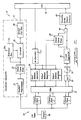
- FIG. 2 shows a functional block diagram of a hardware system 10 for performing the acquisition method previously described.
- the correlation subsystem 12 shown in the dotted portion of FIG. 2 and the scene differencing and segmentation subsystem 14 which forms the remainder of the figure.
- the correlation subsystem 12 performs the scene registration function to align the current image with the previous images. Any one of a number of registration techniques can be applied. In the preferred embodiment a maskable bilevel correlator is used.
- the correlator takes the current image and compares it to portions of a previous image to estimate the position offset between the two images.
- the offset estimate is made available to the CPU 16 which then uses this information in the scene differencing subsystem.
- the incoming video from the sensor 18 is stored in one of three framestores 1, 2 and 3.
- the live (most recent) data is stored in the framestore which holds the oldest data.
- the routing of data storage is controlled by the CPU 16 through the input address generator 20.
- the three images in storage at a given time are defined as images N, N-1, and N-2 with image N being the most recent image. Images N, N-1, N-2 are stored in framestores 1, 2, and 3 respectively. (The specific assignment of the images into their respective framestores are for the purpose of this discussion only. In general, the assignment is arbitrary and is controlled by the CPU.)
- image N As image N is read out of the sensor 18, it is preprocessed and stored in the trilevel framestore 22 of the correlation subsystem 12.
- the portions of image N-2 which are stored in the reference RAM 24 of the correlator are loaded into the convolver 26 and convolved with the preprocessed live image.
- the offset between images N and N-2 is estimated from the position of the correlation peak and made available to the CPU 16 via scratch pad RAM 28.
- the CPU then accesses image N out of framestore 1 through output address generator 1 and image N-2 out of framestore 3 through output address generator 2.
- the addressing of output address generator 2 is offset from the addressing of output address generator 1 with the image shift estimated from the correlation subsystem 12.
- the corresponding pixels in the two images (N and N-2) are read out simultaneously from the framestores 1, 3 and fed into the arithmetical logical unit (ALU) 30 via the crossbar switch (XBAR) 32.
- the ALU 30 subtracts each pixel from image N-2 from the corresponding pixel from image N.
- the difference pixels are then buffered and averaged in the low-pass filter (LPF) 34.
- the LPF 34 is a two-dimensional finite impulse response (FIR) filter of 5x5 size with a constant weighting coefficient of 1 for each element of the FIR filter.
- the segmented three-level data are stored in the trilevel framestore 38.
- the addressing of the storage is controlled by output generator 1. This addressing scheme assures that the trilevel image has the same coordinate system as input image N.
- the offset between images N and N-1 is being estimated by the correlation subsystem 12. This estimation is performed in the same manner as previously described for images N and N-2 except that portions of image N-1 are now accessed out of the reference RAM 24 by the convolver in the performance of the correlation process.
- a segmented difference image between images N and N-1 is formed as before with the CPU now commanding output address generator 2 to access image N-1 out of framestore 2.
- thresholded difference image (N, N-1) is formed by the three-level segmenter 36
- the corresponding pixel in thresholded difference image (N, N-2) is read out of the trilevel framestore 38 by output address generator 1.
- the pixels from the two thresholded difference images are ANDed together at gate 39 according to the truth table shown in FIG. 3 to form a validated difference image.
- the validated difference image is then passed to the formatter, sorter, and feature extractor 40 where spatially connected pixels of state +1 are grouped together to form +1 polarity blobs and spatially connected pixels of state -1 are grouped together to form -1 polarity blobs.
- the feature extractor computes the spatial moments M00, M10, M01 and the coordinates of the bounding rectangle for each blob.
- the blobs found in the first validated difference image define a set of track files with one file created for each blob.
- Each file is tagged by its state ( ⁇ 1), its center of mass (M10/M00, M01/M00), and its extents (the bounding rectangle).
- Blobs detected in subsequent validated difference images are checked against existing track files in the CPU 16.
- a track file which has a blob of corresponding state in the current validated difference image with reasonable agreement in position and extents is said to have found a match.
- the number of matches for a track file over the most recent N attempts is accumulated.
- Those track files which failed to find at least K matches out of N attempts are deleted.
Landscapes
- Engineering & Computer Science (AREA)
- Physics & Mathematics (AREA)
- General Physics & Mathematics (AREA)
- Multimedia (AREA)
- Remote Sensing (AREA)
- Radar, Positioning & Navigation (AREA)
- Electromagnetism (AREA)
- Computer Vision & Pattern Recognition (AREA)
- Theoretical Computer Science (AREA)
- Image Analysis (AREA)
- Image Processing (AREA)
- Closed-Circuit Television Systems (AREA)
- Geophysics And Detection Of Objects (AREA)
- Radar Systems Or Details Thereof (AREA)
Applications Claiming Priority (2)
| Application Number | Priority Date | Filing Date | Title |
|---|---|---|---|
| US229390 | 1988-08-08 | ||
| US07/229,390 US4937878A (en) | 1988-08-08 | 1988-08-08 | Signal processing for autonomous acquisition of objects in cluttered background |
Publications (2)
| Publication Number | Publication Date |
|---|---|
| EP0380658A1 EP0380658A1 (en) | 1990-08-08 |
| EP0380658B1 true EP0380658B1 (en) | 1993-11-03 |
Family
ID=22861028
Family Applications (1)
| Application Number | Title | Priority Date | Filing Date |
|---|---|---|---|
| EP89911440A Expired - Lifetime EP0380658B1 (en) | 1988-08-08 | 1989-07-03 | Signal processing for autonomous acquisition of objects in cluttered background |
Country Status (11)
| Country | Link |
|---|---|
| US (1) | US4937878A (tr) |
| EP (1) | EP0380658B1 (tr) |
| JP (1) | JPH0664613B2 (tr) |
| KR (1) | KR930007549B1 (tr) |
| AU (1) | AU619611B2 (tr) |
| CA (1) | CA1313704C (tr) |
| DE (1) | DE68910498T2 (tr) |
| ES (1) | ES2016049A6 (tr) |
| IL (1) | IL90898A (tr) |
| TR (1) | TR25266A (tr) |
| WO (1) | WO1990001706A2 (tr) |
Families Citing this family (66)
| Publication number | Priority date | Publication date | Assignee | Title |
|---|---|---|---|---|
| KR930006386B1 (ko) * | 1988-08-08 | 1993-07-14 | 휴우즈 에어크라프트 캄파니 | 이동 목표물을 분절하여 검출하는 방법 및 검출장치 |
| IT1232109B (it) * | 1989-06-21 | 1992-01-23 | Cselt Centro Studi Lab Telecom | Procedimento e dispositivo di riconoscimento del contorno di immagini in movimento |
| US4958224A (en) * | 1989-08-15 | 1990-09-18 | Hughes Aircraft Company | Forced correlation/mixed mode tracking system |
| KR100204101B1 (ko) * | 1990-03-02 | 1999-06-15 | 가나이 쓰도무 | 화상처리장치 |
| JPH03269685A (ja) * | 1990-03-19 | 1991-12-02 | Mitsubishi Electric Corp | 高速現象の解析方法及び高速現象撮影装置 |
| FR2662282A1 (fr) * | 1990-05-18 | 1991-11-22 | Philips Electronique Lab | Dispositif de detection d'objets dans une sequence d'images. |
| US5583947A (en) * | 1990-05-18 | 1996-12-10 | U.S. Philips Corporation | Device for the detection of objects in a sequence of images |
| US5177607A (en) * | 1990-08-27 | 1993-01-05 | Zexel Corporation | Method and apparatus for measuring velocity of fluid |
| US5150426A (en) * | 1990-11-20 | 1992-09-22 | Hughes Aircraft Company | Moving target detection method using two-frame subtraction and a two quadrant multiplier |
| FR2670923A1 (fr) * | 1990-12-21 | 1992-06-26 | Philips Lab Electronique | Dispositif de correlation. |
| US5283839A (en) * | 1990-12-31 | 1994-02-01 | Neurosciences Research Foundation, Inc. | Apparatus capable of figure-ground segregation |
| FR2683926B1 (fr) * | 1991-11-15 | 1994-02-18 | Snecma | Procede et dispositif d'acquisition et de traitement d'images radioscopiques. |
| JPH05181970A (ja) * | 1991-12-27 | 1993-07-23 | Toshiba Corp | 動画像処理装置 |
| US5386480A (en) * | 1992-03-09 | 1995-01-31 | Hughes Aircraft Company | Amplitude ratio discrimination for MTI processors |
| US7596242B2 (en) * | 1995-06-07 | 2009-09-29 | Automotive Technologies International, Inc. | Image processing for vehicular applications |
| US5390133A (en) * | 1992-09-30 | 1995-02-14 | Martin Marietta Corporation | Image processor for target detection and tracking |
| US6430303B1 (en) | 1993-03-31 | 2002-08-06 | Fujitsu Limited | Image processing apparatus |
| JP3288474B2 (ja) * | 1993-03-31 | 2002-06-04 | 富士通株式会社 | 画像処理装置 |
| GB9308952D0 (en) * | 1993-04-30 | 1993-06-16 | Philips Electronics Uk Ltd | Tracking objects in video sequences |
| DE69433074D1 (de) * | 1993-07-02 | 2003-10-02 | Siemens Corp Res Inc | Hintergrundrückgewinnung in monokularer Bildverarbeitung |
| JPH07334654A (ja) * | 1994-06-13 | 1995-12-22 | Mitsubishi Electric Corp | 動き検出装置及びその方法 |
| US5521634A (en) * | 1994-06-17 | 1996-05-28 | Harris Corporation | Automatic detection and prioritized image transmission system and method |
| US5509486A (en) * | 1994-08-12 | 1996-04-23 | Loral Corporation | Method of steering an agricultural vehicle |
| US5587929A (en) * | 1994-09-02 | 1996-12-24 | Caterpillar Inc. | System and method for tracking objects using a detection system |
| US5805742A (en) * | 1995-08-16 | 1998-09-08 | Trw Inc. | Object detection system with minimum-spanning gradient filter for scene clutter suppression |
| AUPN903296A0 (en) * | 1996-03-29 | 1996-04-26 | Commonwealth Scientific And Industrial Research Organisation | An aircraft detection system |
| AU720315B2 (en) * | 1996-03-29 | 2000-05-25 | Commonwealth Scientific And Industrial Research Organisation | An aircraft detection system |
| US5974158A (en) * | 1996-03-29 | 1999-10-26 | The Commonwealth Of Australia Commonwealth Scientific And Industrial Research Organization | Aircraft detection system |
| JPH1091795A (ja) * | 1996-09-12 | 1998-04-10 | Toshiba Corp | 移動物体検出装置及び移動物体検出方法 |
| JPH1096605A (ja) * | 1996-09-24 | 1998-04-14 | Komatsu Ltd | 画像処理による位置計測方法および装置 |
| US5960111A (en) * | 1997-02-10 | 1999-09-28 | At&T Corp | Method and apparatus for segmenting images prior to coding |
| US5909190A (en) * | 1997-10-30 | 1999-06-01 | Raytheon Company | Clutter rejection using adaptive estimation of clutter probability density function |
| FR2776459B1 (fr) | 1998-03-19 | 2000-04-28 | France Telecom | Procede de detection des objets en mouvement dans une sequence d'images video |
| EP0973044B1 (de) * | 1998-07-13 | 2006-08-09 | Oerlikon Contraves Ag | Verfahren zur Verfolgung bewegter Objekte anhand spezifischer Merkmale |
| DE19840873A1 (de) * | 1998-09-01 | 2000-03-09 | Deutsch Zentr Luft & Raumfahrt | Verfahren und Vorrichtung zur automatischen Waldbranderkennung |
| US6647131B1 (en) | 1999-08-27 | 2003-11-11 | Intel Corporation | Motion detection using normal optical flow |
| US6654483B1 (en) * | 1999-12-22 | 2003-11-25 | Intel Corporation | Motion detection using normal optical flow |
| US7082209B2 (en) * | 2000-08-31 | 2006-07-25 | Hitachi Kokusai Electric, Inc. | Object detecting method and object detecting apparatus and intruding object monitoring apparatus employing the object detecting method |
| CN1606758A (zh) | 2000-08-31 | 2005-04-13 | 雷泰克公司 | 传感器和成像系统 |
| SE516346C2 (sv) * | 2000-10-06 | 2001-12-17 | Xcounter Ab | Metod för reducering av högfrekvent brus i bilder med hjälp av medelvärdesbildning av pixlar och parvis addering av pixelpar som uppfyller ett villkor |
| US6947575B2 (en) * | 2001-05-24 | 2005-09-20 | Trw Inc. | Apparatus and method for determining vehicle occupant characteristic utilizing imaging with provided light |
| US6810133B2 (en) | 2001-06-01 | 2004-10-26 | Trw Inc. | Occupant sensing system and method via imaging |
| US6961481B2 (en) * | 2002-07-05 | 2005-11-01 | Lockheed Martin Corporation | Method and apparatus for image processing using sub-pixel differencing |
| JP2004046565A (ja) * | 2002-07-12 | 2004-02-12 | Minolta Co Ltd | 動物体のエッジ画像取得方法 |
| DE20218212U1 (de) * | 2002-08-12 | 2003-12-24 | Mit Management Intelligenter Technologien Gmbh | Vorrichtung zur automatischen Adressblockmarkierung |
| US7321699B2 (en) | 2002-09-06 | 2008-01-22 | Rytec Corporation | Signal intensity range transformation apparatus and method |
| JP2005539255A (ja) * | 2002-09-12 | 2005-12-22 | エヌライン、コーパレイシャン | 複合画像を捕捉し、かつ、処理するためのシステムおよび方法複合画像を捕捉し、かつ、処理するためのシステムおよび方法 |
| JP4192719B2 (ja) * | 2003-08-22 | 2008-12-10 | ソニー株式会社 | 画像処理装置および方法、並びにプログラム |
| US7483551B2 (en) * | 2004-02-24 | 2009-01-27 | Lockheed Martin Corporation | Method and system for improved unresolved target detection using multiple frame association |
| JP4686773B2 (ja) * | 2005-06-16 | 2011-05-25 | 独立行政法人海上技術安全研究所 | 動体認識方法および動体認識装置 |
| FR2890451B1 (fr) * | 2005-09-02 | 2009-05-29 | Sagem Defense Securite | Procede de detection d'un objet par traitement spatio-temporel et dispositif de mise en oeuvre du procede |
| US7590303B2 (en) * | 2005-09-29 | 2009-09-15 | Samsung Electronics Co., Ltd. | Image enhancement method using local illumination correction |
| GB2438449C (en) * | 2006-05-24 | 2018-05-30 | Sony Computer Entertainment Europe Ltd | Control of data processing |
| TWI353778B (en) * | 2007-12-21 | 2011-12-01 | Ind Tech Res Inst | Moving object detection apparatus and method |
| US8033612B2 (en) * | 2008-12-24 | 2011-10-11 | Mity-Lite, Inc. | Comfortable mesh folding chair |
| WO2010116400A1 (ja) * | 2009-03-30 | 2010-10-14 | 富士通株式会社 | 被写体動き検出装置および方法 |
| TWI490820B (zh) * | 2010-01-11 | 2015-07-01 | Pixart Imaging Inc | 偵測物體移動之方法及偵測系統 |
| EP2630616A4 (en) * | 2010-10-18 | 2017-03-22 | Nokia Technologies Oy | Method and apparatus for providing hand detection |
| US8831287B2 (en) * | 2011-06-09 | 2014-09-09 | Utah State University | Systems and methods for sensing occupancy |
| US8611600B2 (en) * | 2011-10-12 | 2013-12-17 | Raytheon Company | Three-frame difference moving target acquisition system and method for target track identification |
| CN103196550A (zh) * | 2012-01-09 | 2013-07-10 | 西安智意能电子科技有限公司 | 一种对发射光源的成像信息进行筛选处理的方法与设备 |
| US8983218B2 (en) | 2012-04-11 | 2015-03-17 | Texas Instruments Incorporated | Virtual boundary processing simplification for adaptive loop filtering (ALF) in video coding |
| US9111444B2 (en) | 2012-10-31 | 2015-08-18 | Raytheon Company | Video and lidar target detection and tracking system and method for segmenting moving targets |
| US9369742B2 (en) | 2012-12-06 | 2016-06-14 | Avaya Inc. | System and method to estimate end-to-end video frame delays |
| US10977808B2 (en) | 2019-02-18 | 2021-04-13 | Raytheon Company | Three-frame difference target acquisition and tracking using overlapping target images |
| CN117572885B (zh) * | 2023-11-20 | 2024-05-31 | 鸣飞伟业技术有限公司 | 基于无人机热红外相机的夜间追踪方法、系统及相关装置 |
Family Cites Families (10)
| Publication number | Priority date | Publication date | Assignee | Title |
|---|---|---|---|---|
| US4220967A (en) * | 1976-09-27 | 1980-09-02 | Hughes Aircraft Company | Scene tracker using multiple independent correlators |
| US4405940A (en) * | 1977-05-31 | 1983-09-20 | Westinghouse Electric Corp. | Apparatus and method for preprocessing video frame signals |
| JPS5994045A (ja) * | 1982-11-22 | 1984-05-30 | Toshiba Corp | 画像入力装置 |
| IL69327A (en) * | 1983-07-26 | 1986-11-30 | Elscint Ltd | Automatic misregistration correction |
| US4739401A (en) * | 1985-01-25 | 1988-04-19 | Hughes Aircraft Company | Target acquisition system and method |
| US4639774A (en) * | 1985-06-21 | 1987-01-27 | D. L. Fried Associates, Inc. | Moving target indication system |
| JPS6226992A (ja) * | 1985-07-29 | 1987-02-04 | Nippon Telegr & Teleph Corp <Ntt> | 移動物体抽出方式 |
| JP2585544B2 (ja) * | 1986-09-12 | 1997-02-26 | 株式会社日立製作所 | 動き検出回路 |
| JP2718668B2 (ja) * | 1986-10-06 | 1998-02-25 | 株式会社日立製作所 | 動き検出回路 |
| US4959714A (en) * | 1988-08-08 | 1990-09-25 | Hughes Aircraft Company | Segmentation method for terminal aimpoint determination on moving objects and apparatus therefor |
-
1988
- 1988-08-08 US US07/229,390 patent/US4937878A/en not_active Expired - Lifetime
-
1989
- 1989-07-03 EP EP89911440A patent/EP0380658B1/en not_active Expired - Lifetime
- 1989-07-03 WO PCT/US1989/002877 patent/WO1990001706A2/en not_active Ceased
- 1989-07-03 AU AU44005/89A patent/AU619611B2/en not_active Ceased
- 1989-07-03 JP JP1510627A patent/JPH0664613B2/ja not_active Expired - Lifetime
- 1989-07-03 DE DE89911440T patent/DE68910498T2/de not_active Expired - Fee Related
- 1989-07-07 IL IL90898A patent/IL90898A/xx not_active IP Right Cessation
- 1989-07-13 CA CA000605619A patent/CA1313704C/en not_active Expired - Fee Related
- 1989-08-03 ES ES8902762A patent/ES2016049A6/es not_active Expired - Fee Related
- 1989-08-08 TR TR89/0602A patent/TR25266A/tr unknown
-
1990
- 1990-04-06 KR KR1019900700719A patent/KR930007549B1/ko not_active Expired - Fee Related
Non-Patent Citations (3)
| Title |
|---|
| PATENT ABSTRACTS OF JAPAN, vol.11,no.351 (E-557)(2798), 17 November 1987;& JP-A-62128288 * |
| PATENT ABSTRACTS OF JAPAN, vol.12,no.414 (E-677)(3261), 2 November 1988;& JP-A-63151282 * |
| PATENT ABSTRACTS OF JAPAN,vol.12,no.412 (E-676)(3259), 31 October 1988;& JP-A-63148790 * |
Also Published As
| Publication number | Publication date |
|---|---|
| KR900702378A (ko) | 1990-12-06 |
| WO1990001706A2 (en) | 1990-02-22 |
| JPH0664613B2 (ja) | 1994-08-22 |
| JPH03502018A (ja) | 1991-05-09 |
| ES2016049A6 (es) | 1990-10-01 |
| EP0380658A1 (en) | 1990-08-08 |
| US4937878A (en) | 1990-06-26 |
| DE68910498D1 (de) | 1993-12-09 |
| WO1990001706A3 (en) | 1990-03-22 |
| CA1313704C (en) | 1993-02-16 |
| TR25266A (tr) | 1992-12-04 |
| AU4400589A (en) | 1990-03-05 |
| IL90898A (en) | 1993-04-04 |
| AU619611B2 (en) | 1992-01-30 |
| DE68910498T2 (de) | 1994-03-03 |
| KR930007549B1 (ko) | 1993-08-12 |
Similar Documents
| Publication | Publication Date | Title |
|---|---|---|
| EP0380658B1 (en) | Signal processing for autonomous acquisition of objects in cluttered background | |
| Tom et al. | Morphology-based algorithm for point target detection in infrared backgrounds | |
| US5109435A (en) | Segmentation method for use against moving objects | |
| JPH04268477A (ja) | 2フレーム減算を使用した運動目標検出方法および装置 | |
| Holmes et al. | Adaptive multispectral CFAR detection of land mines | |
| US6081605A (en) | Clutter rejection through edge integration | |
| US7646886B2 (en) | Closely-spaced multiple targets detection using a regional window as a discriminant function | |
| Diani et al. | Space–time processing for the detection of airborne targets in IR image sequences | |
| JP2618172B2 (ja) | Mtiプロセッサ用振幅比弁別システム | |
| Wang | A pipeline algorithm for detection and tracking of pixel-sized target trajectories | |
| KR930006386B1 (ko) | 이동 목표물을 분절하여 검출하는 방법 및 검출장치 | |
| Beck | Image enhancement and moving-target detection in IR image sequences | |
| Wang et al. | Detection and tracking of single-pixel targets based on trajectory continuity | |
| Tzannes et al. | Point target detection in IR image sequences based on target and clutter temporal profile modeling | |
| Tisdale | A Digital Image Processor for Automatic Target Cueing, Navigation, and Change Detection | |
| Tzannes et al. | Point target detection in ir image sequences using spatio-temporal hypotheses testing | |
| Chen et al. | Robust extended target detection using nonlinear morphological operations | |
| Koligman et al. | Automated video and infrared tracking technology | |
| Attili et al. | False track discrimination in a 3D signal/track processor | |
| Baldacci et al. | Generalized likelihood ratio test approach to multiframe infrared detection of moving objects | |
| Toumodge | Detection and tracking of small targets in persistence | |
| Warren | The Performance of Small Support Spatial and Temporal Filters for Dim Point Target Detection in Infrared Image Sequences | |
| Pergande et al. | Simple image processing with MMW cameras | |
| Zhanghong et al. | A real-time effective method for infrared point-target detection in spatially varying clutter | |
| Sullivan | IRAR Image Processing Techniques. |
Legal Events
| Date | Code | Title | Description |
|---|---|---|---|
| PUAI | Public reference made under article 153(3) epc to a published international application that has entered the european phase |
Free format text: ORIGINAL CODE: 0009012 |
|
| 17P | Request for examination filed |
Effective date: 19900222 |
|
| AK | Designated contracting states |
Kind code of ref document: A1 Designated state(s): CH DE FR GB IT LI NL SE |
|
| 17Q | First examination report despatched |
Effective date: 19920521 |
|
| GRAA | (expected) grant |
Free format text: ORIGINAL CODE: 0009210 |
|
| AK | Designated contracting states |
Kind code of ref document: B1 Designated state(s): CH DE FR GB IT LI NL SE |
|
| REF | Corresponds to: |
Ref document number: 68910498 Country of ref document: DE Date of ref document: 19931209 |
|
| ET | Fr: translation filed | ||
| ITF | It: translation for a ep patent filed | ||
| PGFP | Annual fee paid to national office [announced via postgrant information from national office to epo] |
Ref country code: FR Payment date: 19940609 Year of fee payment: 6 |
|
| PGFP | Annual fee paid to national office [announced via postgrant information from national office to epo] |
Ref country code: SE Payment date: 19940615 Year of fee payment: 6 |
|
| PGFP | Annual fee paid to national office [announced via postgrant information from national office to epo] |
Ref country code: GB Payment date: 19940620 Year of fee payment: 6 |
|
| PGFP | Annual fee paid to national office [announced via postgrant information from national office to epo] |
Ref country code: DE Payment date: 19940627 Year of fee payment: 6 Ref country code: CH Payment date: 19940627 Year of fee payment: 6 |
|
| PGFP | Annual fee paid to national office [announced via postgrant information from national office to epo] |
Ref country code: NL Payment date: 19940731 Year of fee payment: 6 |
|
| PLBE | No opposition filed within time limit |
Free format text: ORIGINAL CODE: 0009261 |
|
| STAA | Information on the status of an ep patent application or granted ep patent |
Free format text: STATUS: NO OPPOSITION FILED WITHIN TIME LIMIT |
|
| 26N | No opposition filed | ||
| EAL | Se: european patent in force in sweden |
Ref document number: 89911440.9 |
|
| PG25 | Lapsed in a contracting state [announced via postgrant information from national office to epo] |
Ref country code: GB Effective date: 19950703 |
|
| PG25 | Lapsed in a contracting state [announced via postgrant information from national office to epo] |
Ref country code: SE Effective date: 19950704 |
|
| PG25 | Lapsed in a contracting state [announced via postgrant information from national office to epo] |
Ref country code: LI Effective date: 19950731 Ref country code: CH Effective date: 19950731 |
|
| PG25 | Lapsed in a contracting state [announced via postgrant information from national office to epo] |
Ref country code: NL Effective date: 19960201 |
|
| GBPC | Gb: european patent ceased through non-payment of renewal fee |
Effective date: 19950703 |
|
| REG | Reference to a national code |
Ref country code: CH Ref legal event code: PL |
|
| NLV4 | Nl: lapsed or anulled due to non-payment of the annual fee |
Effective date: 19960201 |
|
| PG25 | Lapsed in a contracting state [announced via postgrant information from national office to epo] |
Ref country code: DE Effective date: 19960402 |
|
| EUG | Se: european patent has lapsed |
Ref document number: 89911440.9 |
|
| PG25 | Lapsed in a contracting state [announced via postgrant information from national office to epo] |
Ref country code: FR Effective date: 19960430 |
|
| REG | Reference to a national code |
Ref country code: FR Ref legal event code: ST |
|
| REG | Reference to a national code |
Ref country code: FR Ref legal event code: ST |
|
| REG | Reference to a national code |
Ref country code: FR Ref legal event code: ST |
|
| PG25 | Lapsed in a contracting state [announced via postgrant information from national office to epo] |
Ref country code: IT Free format text: LAPSE BECAUSE OF NON-PAYMENT OF DUE FEES;WARNING: LAPSES OF ITALIAN PATENTS WITH EFFECTIVE DATE BEFORE 2007 MAY HAVE OCCURRED AT ANY TIME BEFORE 2007. THE CORRECT EFFECTIVE DATE MAY BE DIFFERENT FROM THE ONE RECORDED. Effective date: 20050703 |