EP0380459A2 - Verarbeitungsverfahren zur Identifizierung eines durch einen Benutzer ausgewählten Anzeigeobjektes für ein interaktives rechnergraphisches Anzeigesystem - Google Patents
Verarbeitungsverfahren zur Identifizierung eines durch einen Benutzer ausgewählten Anzeigeobjektes für ein interaktives rechnergraphisches Anzeigesystem Download PDFInfo
- Publication number
- EP0380459A2 EP0380459A2 EP90850029A EP90850029A EP0380459A2 EP 0380459 A2 EP0380459 A2 EP 0380459A2 EP 90850029 A EP90850029 A EP 90850029A EP 90850029 A EP90850029 A EP 90850029A EP 0380459 A2 EP0380459 A2 EP 0380459A2
- Authority
- EP
- European Patent Office
- Prior art keywords
- coordinate space
- selected area
- data
- inverse
- clipping
- Prior art date
- Legal status (The legal status is an assumption and is not a legal conclusion. Google has not performed a legal analysis and makes no representation as to the accuracy of the status listed.)
- Withdrawn
Links
Images


Classifications
-
- G—PHYSICS
- G06—COMPUTING; CALCULATING OR COUNTING
- G06F—ELECTRIC DIGITAL DATA PROCESSING
- G06F3/00—Input arrangements for transferring data to be processed into a form capable of being handled by the computer; Output arrangements for transferring data from processing unit to output unit, e.g. interface arrangements
- G06F3/01—Input arrangements or combined input and output arrangements for interaction between user and computer
- G06F3/048—Interaction techniques based on graphical user interfaces [GUI]
- G06F3/0484—Interaction techniques based on graphical user interfaces [GUI] for the control of specific functions or operations, e.g. selecting or manipulating an object, an image or a displayed text element, setting a parameter value or selecting a range
- G06F3/04842—Selection of displayed objects or displayed text elements
-
- G—PHYSICS
- G06—COMPUTING; CALCULATING OR COUNTING
- G06T—IMAGE DATA PROCESSING OR GENERATION, IN GENERAL
- G06T15/00—3D [Three Dimensional] image rendering
- G06T15/10—Geometric effects
- G06T15/30—Clipping
Definitions
- This invention relates in general to computer graphics display systems, and more particularly, to a processing method for identifying a displayed object that intersects an operator selected area of the display screen and for enlarging a selected area of the display screen to facilitate operator selection of an object when a complex display it presented.
- Interactive raster graphics systems such as CAD/CAM workstations, are widely used to design components and systems of mechanical, electrical, electromechanical and electronics devices. Frequently, the emphasis within such systems is on an operator's interacting with a computer based model of a component or system being designed in order to test, for example, its mechanical, electrical or thermal properties.
- the computer based model is comprised of numerous graphics objects that are individually processed and displayed for operator action. Selection of a display object is accomplished via any one of a number of operator controlled interaction devices, such as light pens, locators (e.g., a data tablet with stylus), and alphanumeric and function keyboards.
- An important part of many interaction sequences is computer identification of an operator selected displayed object to be operated upon, a process which is complicated by the pipeline processing techniques utilized within most graphics systems today.
- graphics system processing techniques require the reprocessing of an entire display screen to identify a particular displayed object selected or picked for further processing. More particularly, existing processing methods require the reexecution of the whole display program, including: transformation of each geometric primitive defining a displayed object in world coordinate space; clipping of each transformed primitive against the predefined clipping boundary in world coordinate space; mapping of each clipped primitive to an operator defined viewport in screen coordinate space; rasterization of all mapped data; and finally, determination of whether the generated pixels intersect the operator defined selection area or window in screen coordinate space. If so, then a pick occurs.
- this invention comprises an improved method for identifying displayed primitives that intersect an operator selected area of the second coordinate space.
- the method comprises the steps of: inverse mapping the second coordinate space selected area to first coordinate space; clipping the data list representative of displayed geometric primitives against the inverse mapped selected area; and selecting the clipped data representative of displayed geometric primitives that intersect the inverse mapped selected area in the first coordinate space.
- the invention comprises a processing method for enlarging displayed primitives that intersect an operator selected area of the second coordinate space to facilitate operator selection of a particular displayed object.
- the method includes the steps of: inverse mapping the second coordinate space selected area to the first coordinate space; clipping the data list representative of displayed geometric primitives against the inverse mapped selected area in the first coordinate space and discarding data outside the inverse mapped area; mapping the clipped data that intersects the inverse mapped selected area to a zoom viewport within the second coordinate space; and rasterizing the mapped data for display within the second coordinate space zoom viewport.
- the identification processing method outlined above can then be combined with this aspect of the invention to identify an operator selected displayed object within the zoom viewport.
- a principal object of the present invention is to provide a graphics system identification processing method capable of efficiently and quickly evaluating displayed data to identify those geometric primitives that intersect an operator selected area of the display screen.
- Another object of the present invention is to provide such an identification processing method wherein only primitives that intersect the operator selected area of the display screen are mapped to and rasterized in screen coordinate space.
- Yet another object of the present invention is to provide an improved graphics system processing method capable of efficiently and quickly zooming out a selected area of the display screen to facilitate selection of a particular geometric object from a complex screen display.
- Still another object of the present invention is to provide such a zoom processing method wherein only objects that intersect the operator selected area of the display screen are mapped to and rasterized in screen coordinate space.
- This invention comprises an improved interactive raster graphics display system processing method for identifying an operator selected displayed object which requires rerasterization of only a limited portion of the original display data, thus dramatically reducing processing time. Further, the invention comprises an analogous graphics system processing technique for zooming out or enlarging objects displayed in a limited portion of the monitor screen surrounding the center of a locating device, to facilitate operator selection of a particular displayed object when a complex display is presented. Only the contents of a "zoom window" defined in world coordinate space are rerasterized, again significantly reducing processing time over prior zoom techniques.
- System 10 includes system memory 12, display processor 14, pixel processor 16, video pixel memory 18, monitor 20 and selector device 22.
- display processor 14 is responsible for executing the display program residing within system memory 12 and functions principally to generate the image which will appear on display monitor 20.
- Display processor 14 performs the following functions: decoding graphics orders and executing nondrawing orders, e.g., bookkeeping and control; performing transformation and clipping functions to geometric primitives, such as lines, characters, polygons, etc.; preparing geometric objects or primitives for display by preprocessing and feeding data representative thereof to pixel processor 16 and video pixel memory 18; and if an operator selection or pick occurs, processing the selected data and sending it back to the application program.
- Pixel processor 16 includes a hardware implementation of the Bresenham Line Generation Algorithm, which takes the end points of a vector as input (i.e., x-axis and y-axis coordinates) and generates pixels in video pixel memory 18 as output for display on monitor 20.
- Processor 16 also contains hardware for pixel manipulation, such as logical operations, bit block transfer, etc.
- Video pixel memory 18 consists of eight 1k by 1k bit planes which support simultaneous display of up to 256 colors via color look-up tables. The image stored in video pixel memory 18 is displayed in monitor 20 for operator viewing.
- Selector device 22 is connected to processor 14 and allows direct operator interaction with system 10.
- locators comprise the vast majority of such devices, tablets being perhaps most common.
- a tablet is a flat surface over which a stylus (like a pencil) or hand cursor is moved. The position of the hand cursor or stylus is transferred to processor 14 of system 10.
- Most cursors also provide the operator with several function keys, such as the "pick” and "zoom” functions to which the present invention is directed. Actuation of a function key directs the processor go begin the desired processing with reference to the current location of the selector device. Tablets are well known in the art and numerous versions are commercially available.
- Clipping instruction 46 essentially directs the processor to remove those parts of a displayed object, or more particularly, one or more geometric primitives definitive thereof, not within a defined clipping volume (3D clipping) or area (2D clipping).
- processor 14 is directed to map the clipped data to a predefined display viewport in screen coordinate space, "Window-to-Viewport Mapping" 48, and then to rasterize the mapped object, "Rasterize Mapped Object" 50.
- the display processor is directed to finally determine whether the pixels generated during rasterization intersect the operator defined pick window or area in screen coordinate space, "Check For Pick And Log Picked Data" 52. If an intersection is identified, a pick occurs and the display processor records the object for subsequent processing according to the application rules set by the operator.
- the present invention comprises a processing technique whereby only those geometric objects intersecting the pick area in screen coordinate space are ultimately rasterized from world coordinate space to screen coordinate space.
- each primitive geometrically oriented in a 3D or 2D world coordinate space (such as a vector, circle, curve or filled polygon) representative, in whole or in part, of a displayed object (in screen coordinate space) undergoes the traditional transformation and clipping functions in world coordinate space, and possibly mapping to screen coordinate space as described below.
- the first stage of processing data representative of a displayed primitive comprises transformation of the primitive in world coordinate space. Transformation may consist of a rotation, translation, scaling, shearing, or a combination of two or more of these functions, and is accomplished by matrix multiplication.
- the second processing stage is clipping of the data against an operator defined clipping box (3D) or window (2D) in world coordinate space. Clipping discards that portion of a geometric primitive outside the box or window.
- the next stage is to map the clipped data to screen coordinate space, i.e., to a predefined viewport in the display screen.
- the predefined boundaries of a clipping window 34 in world coordinate space are: xclip1,xclip2 x-clipping boundary yclip1,yclip2 y-clipping boundary zclip1,zclip2 z-clipping boundary (not shown).
- xv and yv comprise the corresponding mapped x- and y-coordinates of the primitive within viewport 32 in screen coordinate space (Fig. 3B) from screen coordinate space to world coordinate space such that an inverse pick window 30 (Fig. 3A) is defined).
- the boundary of inverse pick window 36 is then used as the x-axis and y-axis clipping boundaries by processor 14 to initially identify in world coordinate space the operator selected geometric primitive(s) defining a displayed object, as will now be described with reference to Figure 4.
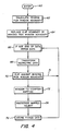
- the processor Upon entering the selection processing mode of the present invention at 60 "Start", for example in response to operator actuation of a function key, the processor is directed to calculate the inverse pick window boundary 36 (Fig. 3A), "Calculate Inverse Pick Window Boundary" 62.
- the size of the pick window (in screen coordinates), psizex and psizey, is preconfigured by the operator.
- the center, pickx and picky, of the pick window in screen coordinate space is defined by the position of the operator controlled selector device 22.
- An inverse pick box (not shown) in 3D world coordinate space could alternatively be defined if desired, by using the preexisting z-axis clipping boundaries, i.e., zclip1 and zclip2, in combination with the inverse pick window parameters defined by equations (4).
- processor 14 After calculating the inverse pick window boundary, processor 14 is directed to replace the previously defined clipping window boundary 34 by the inverse pick window boundary 36, "Replace Clip Boundary By Inverse Pick Window Boundary" 64. Subsequently, the processor enters the main pick correlation processing loop at instruction 66 "If Not End Of Data, Fetch Data", where the processor is directed to obtain the next piece of data from the data list representative of displayed objects for performance of transformation and clipping, and possibly mapping and rasterization, operations thereon. Specifically, the processor transforms each piece of data "Transform Geometric Data” 68, and then clips it against the inverse pick window boundary 36, "Clip against Inverse Pick Window Boundary" 70.
- trivial rejection clipping is utilized to further limit the processing time required for complex geometric primitives such as circles, ellipses, and filled area polygons.
- Curved objects such as circles and ellipses, are typically represented by a plurality of line segments generated directly from an appropriate curve parametric equation. These line segments are then individually transformer, clipped, and mapped, a process which is very time consuming, and unnecessary if the transformed curved figure lies entirely outside the inverse pick window boundary.
- a trivial clip or extend test which essentially generates a box around the primitive and determines whether the box intersects the clipping window, is preferably utilized to determine whether a primitive lies entirely outside the inverse pick window boundary.
- the clipped data is mapped to the viewport in screen coordinate space "Window-To-Viewport Mapping" 72, and then rasterized, via pixel processor 16, "Rasterize Mapped Object” 74.
- the picking or selection of an object occurs during the rasterization step 74 when the generated pixels of an object are compared to the pick window.
- Some graphics processors have the ability to identify picked objects prior to mapping and rasterization. In such a device steps 72 and 74 may be omitted with processing proceeding directly from step 70 to step 76.
- the processor stores the picked data "Store Picked Data" 76 and processes the data according to the rules set by the application program.
- this processing technique eliminates the rasterization and examination of any geometric primitive not intersecting the inverse pick window, and therefore the pick window, thereby significantly reducing pick correlation time, especially when there are a number of complex primitives such as filled polygons or widened lines on the display screen.
- an efficient zoom processing technique is provided.
- a "zoom" function is often available in graphics system to facilitate operator selection of a geometric primitive in an area of a complex display screen crowded with many displayed objects.
- only the contents of a zoom window are rasterized pursuant to this invention, thus significantly reducing processing time in comparison with prior zoom processing techniques, which again typically require rerasterization of the entire display screen.
- zoom window 110 is defined in world coordinate space as a rectangle which con tains an inverse pick window 112.
- the pick window 114 size in screen coordinate space is defined to be psizex and psizey, and its center, pickx and picky, in screen coordinate space is determined by the position of the operator controlled locator device.
- inverse window-to-viewport mapping to pick window 114 (i.e. equations (3) and (4) above)
- values for parameters x1, x2, y1 and y2 definitive of inverse pick window 112 in world coordinate space are obtained.
- the zoom window in world coordinate space is arbitrarily redefined herein to be sixteen times as large as the inverse pick window.
- Xview1 and yview1 are the x-axis and y-axis minimum boundaries, respectively, of viewport 118 in screen coordinate space
- xclip1 and yclip1 are the x-axis and y-axis minimum boundaries, respectively, of the predefined clipping window in world coordinate space.
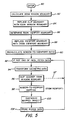
- the processor is directed to replace the preexisting clipping boundary in world coordinate space with the zoom window boundary, "Replace Clip Boundary With Zoom Window Boundary” 84, and then to obtain the zoom viewport boundary, "Determine Zoom Viewport Boundary" 86.
- the zoom viewport 116 is a rectangular area in screen coordinate space of any size defined, i.e. preconfigured, by the operator. As shown in Figure 6B, viewport 116 is expressed by parameters zoomvx1, zoomvx2, zoomvy1, and zoomvy2. If desired, the zoom viewport can overlay the original data on the screen, similar to a pop-up window.
- the processor next replaces the original viewport boundary 118 (Fig. 6B) with the zoom viewport boundary 116, "Replace Viewport Boundary With Zoom Viewport Boundary” 88, and then calculates the new window-to-viewport ratio, "Recalculate Window-to-Viewport Ratio" 90. Recalculation of the window-to-viewport ratio is necessary because, as noted, zoom viewport 116 is operator defined and possibly different in size from original viewport 118.
- the processor enters the main processing loop at 92 "If Not End Of Data, Fetch Data", where processor 14 begins to work through the data list representative of displayed geometric primitives.
- each piece of data representative of a geometric primitive is transformed "Transform Geometric Data” 94, and clipped against the new clipping boundary, i.e., the zoom window boundary 110 (Fig. 6A), "Clip against Zoom Window Boundary” 96.
- those primitives outside the clipping boundary, i.e. the zoom window boundary are discarded and the processor returns to instruction 92 via line 97.
- trivial clip testing is also utilized as described above to enhance processing time.
- the processor is directed to map the retained clipped data to zoom viewport 116 in screen coordinate space using the recalculated window-to-viewport ration, "Window-To-Viewport Mapping” 98, and then to rasterize the mapped object, "Rasterize Mapped Object” 100. Thereafter, the processor stores the object for display on the screen within the zoom viewport, "Store Picked Data” 102. The operator can then use the locator device to initiate a select or pick operation from the geometric objects within the zoom viewport, which will be processed in the same manner as described with reference to Figure 4.
Landscapes
- Engineering & Computer Science (AREA)
- Physics & Mathematics (AREA)
- Theoretical Computer Science (AREA)
- General Engineering & Computer Science (AREA)
- General Physics & Mathematics (AREA)
- Human Computer Interaction (AREA)
- Geometry (AREA)
- Computer Graphics (AREA)
- Image Generation (AREA)
- Processing Or Creating Images (AREA)
- Digital Computer Display Output (AREA)
Applications Claiming Priority (2)
| Application Number | Priority Date | Filing Date | Title |
|---|---|---|---|
| US299901 | 1989-01-23 | ||
| US07/299,901 US4982345A (en) | 1989-01-23 | 1989-01-23 | Interactive computer graphics display system processing method for identifying an operator selected displayed object |
Publications (2)
| Publication Number | Publication Date |
|---|---|
| EP0380459A2 true EP0380459A2 (de) | 1990-08-01 |
| EP0380459A3 EP0380459A3 (de) | 1992-07-01 |
Family
ID=23156781
Family Applications (1)
| Application Number | Title | Priority Date | Filing Date |
|---|---|---|---|
| EP19900850029 Withdrawn EP0380459A3 (de) | 1989-01-23 | 1990-01-22 | Verarbeitungsverfahren zur Identifizierung eines durch einen Benutzer ausgewählten Anzeigeobjektes für ein interaktives rechnergraphisches Anzeigesystem |
Country Status (3)
| Country | Link |
|---|---|
| US (1) | US4982345A (de) |
| EP (1) | EP0380459A3 (de) |
| JP (1) | JPH02230470A (de) |
Cited By (6)
| Publication number | Priority date | Publication date | Assignee | Title |
|---|---|---|---|---|
| EP0481581A2 (de) * | 1990-10-15 | 1992-04-22 | Picker International, Inc. | Gerät und Verfahren zur Bildverarbeitung |
| EP0520397A2 (de) * | 1991-06-28 | 1992-12-30 | Acoustic Imaging Technologies Corporation | Gerät und Verfahren zur Bilderzeugung mit Ultraschall |
| EP0526918A2 (de) * | 1991-06-12 | 1993-02-10 | Ampex Systems Corporation | Bildtransformation über eine gefaltete gekrümmte Oberfläche |
| EP0889437A2 (de) * | 1997-04-14 | 1999-01-07 | Adobe Systems, Inc. | System zur Abbildung von Rasterbildern |
| WO2006063888A1 (en) * | 2004-12-16 | 2006-06-22 | Agfa Inc. | System and method for image transformation |
| CN108564523A (zh) * | 2018-04-12 | 2018-09-21 | 长沙景美集成电路设计有限公司 | Gpu中一种任意视口变换的实现方法 |
Families Citing this family (39)
| Publication number | Priority date | Publication date | Assignee | Title |
|---|---|---|---|---|
| JP2792564B2 (ja) * | 1989-02-15 | 1998-09-03 | キヤノン株式会社 | 図形編集装置 |
| US5581796A (en) * | 1989-03-07 | 1996-12-03 | Hitachi, Ltd. | Processing method and graphics processor for skip drawing a figure |
| US5252951A (en) * | 1989-04-28 | 1993-10-12 | International Business Machines Corporation | Graphical user interface with gesture recognition in a multiapplication environment |
| US5208909A (en) * | 1989-10-23 | 1993-05-04 | International Business Machines Corporation | Pre-drawing pick detection in a graphics display system |
| US5148521A (en) * | 1989-10-23 | 1992-09-15 | International Business Machines Corporation | Pick data queue for pipelined graphics system |
| US5185858A (en) * | 1989-12-01 | 1993-02-09 | Megatek Corporation | Image priority video switch |
| JPH06309425A (ja) * | 1990-10-12 | 1994-11-04 | Internatl Business Mach Corp <Ibm> | グラフィックディスプレイ装置及び方法 |
| JPH0797413B2 (ja) * | 1991-05-16 | 1995-10-18 | インターナショナル・ビジネス・マシーンズ・コーポレイション | グラフィックス・システムにおけるピック方法および装置 |
| EP0607130B1 (de) * | 1991-10-10 | 1997-09-03 | Hewlett-Packard Company | Interpretation der bildposition in einem graphischen system. |
| CA2071309C (en) * | 1991-11-15 | 1998-01-20 | Daryl J. Kahl | Method and apparatus utilizing data icons |
| US5384909A (en) * | 1991-12-19 | 1995-01-24 | International Business Machines Corporation | Precision automatic scrolling for an image display system |
| GB2266823A (en) * | 1992-04-21 | 1993-11-10 | Ibm | Correlation of cursor position in a computer system |
| US5485281A (en) * | 1992-07-31 | 1996-01-16 | E. I. Du Pont De Nemours And Company | Raster image processing with pixel mapping to allow image border density allocation |
| US5563990A (en) * | 1992-10-30 | 1996-10-08 | International Business Machines Corporation | Method and apparatus for processing a pick event |
| CA2131414A1 (en) * | 1993-09-22 | 1995-03-23 | Michael Abrash | Fast drawing of 256-color character output with a vga-type adapter |
| US5491494A (en) * | 1993-11-19 | 1996-02-13 | International Business Machines Corporation | Pick correlation |
| JP2972510B2 (ja) * | 1993-11-25 | 1999-11-08 | 株式会社日立製作所 | 文書作成装置 |
| US5483258A (en) * | 1993-12-10 | 1996-01-09 | International Business Machines Corporation | Pick correlation |
| EP0693852A3 (de) * | 1994-07-22 | 1997-05-28 | Eastman Kodak Co | Verfahren und Vorrichtung zur Anwendung einer Funktion in einem Ausschnitt eines digitalen Bildes mittels Fensters |
| WO1996018988A2 (en) * | 1994-12-06 | 1996-06-20 | Cirrus Logic, Inc. | Circuits, systems and methods for controlling the display of blocks of data on a display screen |
| US5748946A (en) * | 1995-02-17 | 1998-05-05 | International Business Machines Corporation | Method and apparatus for improved graphics picking using auxiliary buffer information |
| US5877762A (en) * | 1995-02-27 | 1999-03-02 | Apple Computer, Inc. | System and method for capturing images of screens which display multiple windows |
| US5668941A (en) * | 1995-06-22 | 1997-09-16 | Cirrus Logic, Inc. | Optimum implementation of X-Y clipping on pixel boundary |
| US5709263A (en) * | 1995-10-19 | 1998-01-20 | Silicon Graphics, Inc. | High performance sinusoidal heat sink for heat removal from electronic equipment |
| AUPO951997A0 (en) * | 1997-09-29 | 1997-10-23 | Canon Information Systems Research Australia Pty Ltd | A decoder method and architecture |
| US6630937B2 (en) * | 1997-10-30 | 2003-10-07 | University Of South Florida | Workstation interface for use in digital mammography and associated methods |
| US6229518B1 (en) | 1998-10-07 | 2001-05-08 | Seiko Epson Corporation | Apparatus and method for controlling a software cursor |
| US6271862B1 (en) | 1998-10-07 | 2001-08-07 | Seiko Epson Corporation | Apparatus and method for determining line clipping intersection points |
| US6831660B1 (en) * | 2000-06-15 | 2004-12-14 | International Business Machines Corporation | Method and apparatus for graphics window clipping management in a data processing system |
| US7134093B2 (en) * | 2001-04-18 | 2006-11-07 | International Business Machines Corporation | Graphical user interface for direct control of display of data |
| US6882349B2 (en) * | 2001-12-31 | 2005-04-19 | Intel Corporation | Efficient image allocation for zone rendering |
| US7532753B2 (en) | 2003-09-29 | 2009-05-12 | Lipsky Scott E | Method and system for specifying color of a fill area |
| US8739060B2 (en) * | 2003-09-29 | 2014-05-27 | Eqapez Foundation, L.L.C. | Method and system for displaying multiple aspect ratios of a viewport |
| US20060004697A1 (en) * | 2004-06-09 | 2006-01-05 | Lipsky Scott E | Method and system for restricting the display of images |
| US7348997B1 (en) * | 2004-07-21 | 2008-03-25 | United States Of America As Represented By The Secretary Of The Navy | Object selection in a computer-generated 3D environment |
| DE102004049690A1 (de) * | 2004-10-12 | 2006-04-20 | Siemens Ag | Anzeigeeinheit mit Ansteuerlogik |
| JP5062478B2 (ja) * | 2007-11-28 | 2012-10-31 | ソニー株式会社 | 撮像装置および方法、情報処理装置および方法、並びにプログラム |
| WO2014186972A1 (en) * | 2013-05-24 | 2014-11-27 | Thomson Licensing | Method and apparatus for rendering object for multiple 3d displays |
| CN110688192B (zh) * | 2019-10-15 | 2023-09-15 | 北京思维造物信息科技股份有限公司 | 事件监听响应方法、装置、设备和存储介质 |
Citations (2)
| Publication number | Priority date | Publication date | Assignee | Title |
|---|---|---|---|---|
| EP0172368A2 (de) * | 1984-07-23 | 1986-02-26 | International Business Machines Corporation | Verfahren zur Anzeige eines Bildes |
| EP0231060A2 (de) * | 1986-01-21 | 1987-08-05 | International Business Machines Corporation | Festzeichenreihenabschneidung in einem graphischen Anzeigesystem |
Family Cites Families (15)
| Publication number | Priority date | Publication date | Assignee | Title |
|---|---|---|---|---|
| US3589289A (en) * | 1966-12-22 | 1971-06-29 | Burroughs Corp | Printing members and methods for graphic composition |
| JPS4912767B1 (de) * | 1969-10-16 | 1974-03-27 | ||
| US3725563A (en) * | 1971-12-23 | 1973-04-03 | Singer Co | Method of perspective transformation in scanned raster visual display |
| US3885097A (en) * | 1972-08-11 | 1975-05-20 | Nat Res Dev | Graphical input apparatus for electrical apparatus |
| US4112422A (en) * | 1976-12-13 | 1978-09-05 | Atari, Inc. | Method and apparatus for generating moving objects on a video display screen |
| FR2465284A1 (fr) * | 1979-09-11 | 1981-03-20 | Rabeisen Andre | Systeme de communication televisuelle permettant une creation graphique |
| US4451895A (en) * | 1980-07-17 | 1984-05-29 | Telesis Corporation Of Delaware, Inc. | Interactive computer aided design system |
| US4412296A (en) * | 1981-06-10 | 1983-10-25 | Smiths Industries, Inc. | Graphics clipping circuit |
| US4507523A (en) * | 1982-05-19 | 1985-03-26 | Matsushita Electric Industrial Co., Ltd. | Position determination apparatus |
| JPS60142473A (ja) * | 1983-12-28 | 1985-07-27 | Sony Tektronix Corp | 表示部分検出方法 |
| JPS60194488A (ja) * | 1984-03-15 | 1985-10-02 | ダイキン工業株式会社 | Crtデイスプレイ装置のピツキング処理回路 |
| JP2585515B2 (ja) * | 1985-08-16 | 1997-02-26 | 株式会社日立製作所 | 図形描画方法 |
| US4821209A (en) * | 1986-01-21 | 1989-04-11 | International Business Machines Corporation | Data transformation and clipping in a graphics display system |
| JPS62298883A (ja) * | 1986-06-18 | 1987-12-25 | Fujitsu Ltd | 画像表示装置 |
| US4805117A (en) * | 1986-09-26 | 1989-02-14 | International Business Machines Corporation | Method for controlling concatenation of transformation matrices in a graphics display system |
-
1989
- 1989-01-23 US US07/299,901 patent/US4982345A/en not_active Expired - Fee Related
-
1990
- 1990-01-18 JP JP2007276A patent/JPH02230470A/ja active Pending
- 1990-01-22 EP EP19900850029 patent/EP0380459A3/de not_active Withdrawn
Patent Citations (2)
| Publication number | Priority date | Publication date | Assignee | Title |
|---|---|---|---|---|
| EP0172368A2 (de) * | 1984-07-23 | 1986-02-26 | International Business Machines Corporation | Verfahren zur Anzeige eines Bildes |
| EP0231060A2 (de) * | 1986-01-21 | 1987-08-05 | International Business Machines Corporation | Festzeichenreihenabschneidung in einem graphischen Anzeigesystem |
Non-Patent Citations (1)
| Title |
|---|
| IBM TECHNICAL DISCLOSURE BULLETIN, vol. 25, no. 5, October 1982, pages 2508-2509, New York, US; A.S. MURPHY: "Graphic correlate improvement" * |
Cited By (13)
| Publication number | Priority date | Publication date | Assignee | Title |
|---|---|---|---|---|
| US5297043A (en) * | 1987-11-27 | 1994-03-22 | Picker International, Inc. | Rapid display of rotated and translated three dimensional image representations |
| EP0481581A3 (en) * | 1990-10-15 | 1993-05-26 | Picker International, Inc. | Imaging apparatus and methods |
| EP0481581A2 (de) * | 1990-10-15 | 1992-04-22 | Picker International, Inc. | Gerät und Verfahren zur Bildverarbeitung |
| EP0526918A2 (de) * | 1991-06-12 | 1993-02-10 | Ampex Systems Corporation | Bildtransformation über eine gefaltete gekrümmte Oberfläche |
| EP0526918A3 (de) * | 1991-06-12 | 1994-02-09 | Ampex | |
| EP0520397A3 (en) * | 1991-06-28 | 1993-07-21 | Acoustic Imaging Technologies Corporation | Ultrasound imaging system and method |
| EP0520397A2 (de) * | 1991-06-28 | 1992-12-30 | Acoustic Imaging Technologies Corporation | Gerät und Verfahren zur Bilderzeugung mit Ultraschall |
| EP0889437A2 (de) * | 1997-04-14 | 1999-01-07 | Adobe Systems, Inc. | System zur Abbildung von Rasterbildern |
| EP0889437A3 (de) * | 1997-04-14 | 1999-08-18 | Adobe Systems, Inc. | System zur Abbildung von Rasterbildern |
| US6124858A (en) * | 1997-04-14 | 2000-09-26 | Adobe Systems Incorporated | Raster image mapping |
| WO2006063888A1 (en) * | 2004-12-16 | 2006-06-22 | Agfa Inc. | System and method for image transformation |
| US7496242B2 (en) | 2004-12-16 | 2009-02-24 | Agfa Inc. | System and method for image transformation |
| CN108564523A (zh) * | 2018-04-12 | 2018-09-21 | 长沙景美集成电路设计有限公司 | Gpu中一种任意视口变换的实现方法 |
Also Published As
| Publication number | Publication date |
|---|---|
| EP0380459A3 (de) | 1992-07-01 |
| JPH02230470A (ja) | 1990-09-12 |
| US4982345A (en) | 1991-01-01 |
Similar Documents
| Publication | Publication Date | Title |
|---|---|---|
| US4982345A (en) | Interactive computer graphics display system processing method for identifying an operator selected displayed object | |
| US6870545B1 (en) | Mixed but indistinguishable raster and vector image data types | |
| US5218674A (en) | Hardware bit block transfer operator in a graphics rendering processor | |
| US5012433A (en) | Multistage clipping method | |
| EP0650144B1 (de) | Bildlinse | |
| JP3245655B2 (ja) | 作業スペースの表示処理方法 | |
| KR900006042B1 (ko) | 복합문서 처리 장치용 표시 제어장치 | |
| EP0812447B1 (de) | Computer-grafiksystem zum schaffen und verbessern von texturabbildungssystemen | |
| Bederson et al. | Implementing a zooming user interface: experience building pad++ | |
| US5734806A (en) | Method and apparatus for determining graphical object visibility | |
| JPH10105361A (ja) | オブジェクト指定方法及びシステム | |
| EP0635808A2 (de) | Verfahren und Vorrichtung zum Bearbeiten von Modell-Datenstrukturen eines Bildes, um ein für Menschen erkennbares Resultat zu erreichen | |
| US5966136A (en) | Efficient method for clipping numerous objects against an arbitrary clipping path | |
| US5124693A (en) | Three dimensional graphic display with user defined vanishing point | |
| IE54823B1 (en) | Graphics display method and apparatus | |
| US5003497A (en) | Method for three-dimensional clip checking for computer graphics | |
| US6052128A (en) | Method and apparatus for clipping convex polygons on single instruction multiple data computers | |
| US5175805A (en) | Method and apparatus for sequencing composite operations of pixels | |
| CN111798372A (zh) | 图像渲染方法、装置、设备和可读介质 | |
| EP0658859A2 (de) | Verfahren und Vorrichtung zum Übereinandergreifen graphischer Objekte | |
| US6614445B1 (en) | Antialiasing method for computer graphics | |
| KR20010012841A (ko) | 화상 처리 장치 및 화상 처리 방법 | |
| US6532009B1 (en) | Programmable hardwired geometry pipeline | |
| US6731303B1 (en) | Hardware perspective correction of pixel coordinates and texture coordinates | |
| US6392662B1 (en) | Draw order preservation in a computer-implemented graphics system |
Legal Events
| Date | Code | Title | Description |
|---|---|---|---|
| PUAI | Public reference made under article 153(3) epc to a published international application that has entered the european phase |
Free format text: ORIGINAL CODE: 0009012 |
|
| AK | Designated contracting states |
Kind code of ref document: A2 Designated state(s): DE FR GB |
|
| 17P | Request for examination filed |
Effective date: 19901113 |
|
| PUAL | Search report despatched |
Free format text: ORIGINAL CODE: 0009013 |
|
| AK | Designated contracting states |
Kind code of ref document: A3 Designated state(s): DE FR GB |
|
| STAA | Information on the status of an ep patent application or granted ep patent |
Free format text: STATUS: THE APPLICATION HAS BEEN WITHDRAWN |
|
| 18W | Application withdrawn |
Withdrawal date: 19930323 |