EP0380452A2 - Verfahren und Vorrichtung zur Herstellung von Schmuckketten mit spiralförmigen Gliedern - Google Patents
Verfahren und Vorrichtung zur Herstellung von Schmuckketten mit spiralförmigen Gliedern Download PDFInfo
- Publication number
- EP0380452A2 EP0380452A2 EP90830009A EP90830009A EP0380452A2 EP 0380452 A2 EP0380452 A2 EP 0380452A2 EP 90830009 A EP90830009 A EP 90830009A EP 90830009 A EP90830009 A EP 90830009A EP 0380452 A2 EP0380452 A2 EP 0380452A2
- Authority
- EP
- European Patent Office
- Prior art keywords
- mesh
- free
- link
- chain
- machine
- Prior art date
- Legal status (The legal status is an assumption and is not a legal conclusion. Google has not performed a legal analysis and makes no representation as to the accuracy of the status listed.)
- Granted
Links
- 238000000034 method Methods 0.000 title claims abstract description 13
- 230000000903 blocking effect Effects 0.000 claims abstract description 19
- 230000015572 biosynthetic process Effects 0.000 claims abstract description 15
- 238000006073 displacement reaction Methods 0.000 claims abstract description 6
- 241000334937 Hypsypops rubicundus Species 0.000 claims description 23
- 230000005540 biological transmission Effects 0.000 claims description 2
- 238000004519 manufacturing process Methods 0.000 description 4
- 238000005452 bending Methods 0.000 description 1
- 230000000694 effects Effects 0.000 description 1
- PCHJSUWPFVWCPO-UHFFFAOYSA-N gold Chemical compound [Au] PCHJSUWPFVWCPO-UHFFFAOYSA-N 0.000 description 1
- 229910052737 gold Inorganic materials 0.000 description 1
- 239000010931 gold Substances 0.000 description 1
- 238000007373 indentation Methods 0.000 description 1
- 239000000463 material Substances 0.000 description 1
- 239000002184 metal Substances 0.000 description 1
- 229910052751 metal Inorganic materials 0.000 description 1
- 239000010970 precious metal Substances 0.000 description 1
- 229910052709 silver Inorganic materials 0.000 description 1
- 239000004332 silver Substances 0.000 description 1
Images

Classifications
-
- B—PERFORMING OPERATIONS; TRANSPORTING
- B21—MECHANICAL METAL-WORKING WITHOUT ESSENTIALLY REMOVING MATERIAL; PUNCHING METAL
- B21L—MAKING METAL CHAINS
- B21L11/00—Making chains or chain links of special shape
- B21L11/005—Making ornamental chains
-
- B—PERFORMING OPERATIONS; TRANSPORTING
- B21—MECHANICAL METAL-WORKING WITHOUT ESSENTIALLY REMOVING MATERIAL; PUNCHING METAL
- B21L—MAKING METAL CHAINS
- B21L7/00—Making chains or chain links by cutting single loops or loop-parts from coils, assembling the cut parts and subsequently subjecting same to twisting with or without welding
Definitions
- the invention relates to a method for forming chains with cylindrical helical meshes, for necklaces, bracelets, belts and the like, and a machine for its implementation.
- these chains consist of cylindrical helical meshes of length slightly less than two turns and with a pitch equal to twice the thickness of the wire with which they are made.
- these meshes are assembled by hand, that is to say united together in pairs, by helical rotation of a free mesh with respect to a mesh already assembled by alternately making a free mesh and a fixed mesh, that is to say a set called "Garibaldi module”.
- An ornamental chain to which the invention relates is formed by several "Garibaldi modules”. It is obvious that the manual production of these chains requires a great deal of time and great skill and precision on the part of the operator; consequently, production is limited and the cost very high to the point that it is limited to chains of precious metal such as gold or silver.
- the present invention aims to eliminate the aforementioned drawbacks by proposing a method and a machine for the automatic formation of these chains with helical meshes so as to increase the precision, the speed and the reliability of the production and therefore to reduce drastically manufacturing costs.
- a machine for the automatic formation of chains with “Garibaldi modules” comprises: - A first section for displacements to the mesh of the free meshes, with a support rotating around a vertical axis, with a clamp for taking a free mesh coming from a helical mesh forming machine, said clamp being movable horizontally between an inactive retreat, an advanced gripping position and another advanced position for positioning the free link with respect to the chain link which was last meshed, and further rotating about its longitudinal axis and sliding along it with simultaneous advancement corresponding to the pitch of the helix of the mesh to allow the mesh of the mesh in engagement; - a second section for blocking the front- last assembled link in the chain, with a support rotating around a vertical axis, with two vises mounted to slide horizontally on said support and provided with jaws with indentations corresponding to a helical link, with the ends directed respectively downwards or
- FIG. 1 shows an enlarged view of a helical link for an ornamental chain with "Garibaldi modules”
- FIG. 2 shows the view of a free mesh with two meshes of FIG. 1
- FIG. 3 represents the view of a fixed mesh with two stitches in FIG. 1
- FIG. 4 represents the view of a piece of chain with "Garibaldi modules”
- FIG. 5 shows the plan view of a machine for forming chains according to the invention, associated with a helical mesh forming machine;
- FIG. 1 shows an enlarged view of a helical link for an ornamental chain with "Garibaldi modules”
- FIG. 2 shows the view of a free mesh with two meshes of FIG. 1
- FIG. 3 represents the view of a fixed mesh with two stitches in FIG. 1
- FIG. 4 represents the view of a piece of chain with "Garibaldi modules”
- FIG. 5 shows the plan view of a machine for forming chains according to the invention, associated with a helical mesh forming machine
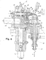
- FIG. 6 shows the sectional view along line BB of FIG. 5;
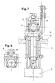
- FIG. 7 shows the sectional view along the line CC of FIG. 6;
- FIG. 8 shows the front view of a detail of the means for advancing the clamp holder shaft for the free meshes;
- FIG. 9 shows the front view of the mesh forming machine indicated in FIG. 5;
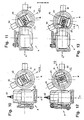
- FIG. 10 shows the schematic plan view of the machine of FIG. 5, in the phase of setting the first stitch for a "Garibaldi module", from a stitch forming machine;
- FIG. 11 shows the machine of FIG. 5 in the free mesh position of the first mesh of the module with the mesh of the chain in formation which was meshed last;
- FIG. 12 shows the machine of FIG. 5, in the setting phase of the second mesh for the module, coming from the mesh forming machine;
- FIG. 13 shows the machine of FIG. 5 in the fixed mesh position of the second mesh of the module with the first mesh of the module.
- Fig. 1 a helical link 1 from which a chain with "Garibaldi modules" is formed; this mesh is made, with known means, from a wire metallic, of predetermined nature and diameter, bent in a helix with a pitch barely more than twice the diameter of the wire and cut so as to obtain meshes of length slightly less than two turns, that is to say approximately 700 ° between the two ends 1a and 1b which are always directed downwards.
- the process for forming chains with "Garibaldi modules” in accordance with the invention comprises, in sequence, the following phases: - blocking of the lower mesh 1 ′ of the last "Garibaldi module” formed previously, maintaining the upper mesh 1 ⁇ with the horizontal axis and with the ends 1a and 1b oriented downwards; and separately: - Taking of a first free mesh 1 ′ in the position in which it is at the outlet of a machine S for the formation of helical meshes 1, and that is to say with the horizontal axis and the two ends 1a and 1b directed downwards; - Positioning of said first mesh 1 ′ so that its longitudinal axis is approximately orthogonal to that of the last mesh 1 ⁇ of the chain in formation and with the free end 1b in the mesh position with mesh 1 ⁇ ; - rotation of said free mesh 1 ′ about its axis, in the direction of the propeller, by about one and a half turns and simultaneous advancement of about one and
- a machine for implementing said method in accordance with the invention and with reference to FIGS. 5 to 8 of the attached drawings consists of: - a first section (A) for the displacements of a free mesh and up to the mesh with the mesh of the chain being formed which was meshed last, and which comprises: - a vertical shaft 12 controlled by a motor device 11, and with an upper horizontal support 13; - A horizontal slide 15 integral with said support 13, with a slide 16 for a clamp holder group 17.
- Said slide has a circular outline with two diametrically opposite planes 18, cooperating with two thrust actuators arranged horizontally at 90 ° l '' with respect to each other, which cause the slide 16 to move forward with the clamp holder: the backward movement of the slide 16 being obtained by means of a spring (not shown) inserted between the slide 16 and the slide 15; - a clamp holder group with a support 22 sliding on a vertical circular sector 23 fixed on said slide 16 with a horizontal shaft 29 whose free end carries a clamp 35 and which is slidably mounted axially on said support 22 and which is rotated by a drive shaft 25 by means of a gear train 26, 27 and 28 with a transmission ratio of 2: 1; with a front cam 30, fixed to the end of the motor shaft 25, which controls the advancement of the shaft 29 by means of a pusher 32 and a lever 31.
- the development of the active profile of the cam 30 is around 270 ° which correspond to a rotation of the clamp holder shaft 29 of around 540 °: the
- said clamp 35 has its jaws provided with an imprint adapted to receive a helical mesh of shape and dimensions corresponding to those of mesh 1.
- the axis of said jaws is parallel to that of the shaft 29 and distant from the latter by a value equal to the radius of the mesh to allow helical movement during meshing.
- the automatic opening of the jaws of the clamp 35 is obtained by means of a spring, at the moment when a rod 36 with wedge-shaped head releases the clamp.
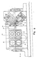
- a second section (B) for blocking the penultimate link of the chain being formed with a sleeve support 41 fixed on a base plate and in which is housed a vertical hollow shaft 42 motorized and whose upper end is shaped like a horizontal slide 43 for a slide 44 for supporting two articulated clamps 45 and 46, juxtaposed in the sliding direction, and alternately positionable in the locking and unlocking position of the corresponding mesh, that is to say on the vertical axis 22 of rotation of the slide 44 and of the shaft 42 in the cavity of which the chain descends during formation; with a hollow rod 47, threaded into the shaft 42, provided with a wedge-shaped head 48 to act on the arm of the clamps 45 and 46, and, moreover, sliding vertically under the action of an actuator E between an upper position for opening the jaws and a lower position for closing the jaws.
- a sleeve support 41 fixed on a base plate and in which is housed a vertical hollow shaft 42 motorized and whose upper end is shaped like a horizontal
- the jaws of said clamps 45 and 46 are provided with imprints suitable for blocking a mesh which is with its ends oriented respectively downwards or upwards. that is to say in the positions suitable for the two types of mesh; with two actuators 49 and 50 to move the support 44 and bring the vice 45 or 46 respectively in the locked position; with a clamp 51 located above the two vices 45 and 46, sliding vertically and adapted to bring the turns of the meshes against each other closer together and with a contrast tip 52 sliding horizontally in a support 53 and intended to penetrate between the end 1a and the central turn of the first mesh 1 ′ which has been meshed, in order to guarantee its locked position during the formation of the fixed mesh with the second mesh 1 ⁇ of the module.
- a machine S for forming helical meshes 1 associated with the machine for forming chains is similar to a machine for producing spiral springs, and essentially comprises several motorized rollers 54 for the horizontal advancement of the metal wire 55 supplied by a coil (not shown) and of the predetermined diameter; two contrast tips 56 and 57, arranged in a vertical plane, at 45 ° to the direction of advancement of the wire, respectively above and below the latter, and with the concave end with circular profile to allow the bending of the wire in circles to the desired diameter; another tip 58 located above and laterally offset with respect to said tips 56 and 57 to generate, with the wire bent in circles, a helix of predetermined pitch, but generally equal to twice the diameter of the wire used; and finally a shear 59 for cutting each mesh in a helix with an angular development slightly less than two turns, for example of about 700 °.
- the operation of a machine for the formation of ornamental chains with "Garibaldi modules” is as follows.
- the clamp 35 of the section A for moving the free meshes is turned towards the machine S for forming the meshes and in the advanced position towards the outside under the effect of the thrust of the actuator 19 on the support 16;
- the shaft 42 of the section A for blocking the assembled meshes is in the lowered position, the axis of the support 44 is oriented along the arrow F1 and in axis with the actuator 50 and the vice 45 is in the active gripping position, that is to say in the blocking position of the lower mesh of a "Garibaldi module" held in the vertical position and the upper mesh of which is in the mesh position.
- the clamp 35 is then closed on the free end of the wire spiral 56 at the outlet of the machine S and a mesh 1 ′ of length slightly less than two turns is cut by the shears 59; after which the support 16 moves back and rotates 90 ° clockwise and simultaneously the actuator 20 brings the support 16 back to the advanced position, by positioning the free end of the free mesh 1 ′ held by the clamp near the mesh 1 ⁇ correspondent waiting for the mesh (see Fig. 11).
- the support 22 then pivots upwards on the sector 23 by tilting the clamp holder shaft 29 by about 20 ° in a vertical plane and the center of which is in correspondence with the end 1b of the free mesh 1 ′ to be mesh; then the clamp holder shaft 29 rotates by about one and a half turns and advances by approximately one and a half steps of the helix of the mesh while obtaining a free mesh of the two meshes concerned.
- the rod 48 rises by opening the vice 45 and the actuator 51 advances the support 44 carrying the second clamp 46 in the gripping position; then the motor shaft 42 pivots clockwise until the axis of the support 44 is in the direction of arrow F2, after which the shaft 42 and the support 44 are raised to bring the vice 46 in correspondence with the mesh 1 ⁇ of the chain located above.
- the clamp 35 is then opened and returned to the rear inactive position and the shaft 12, by pivoting 90 ° counterclockwise, brings, in cooperation with the actuator 19, the clamp 35 open in correspondence with the machine S mesh formation to take a new 1 ⁇ mesh to mesh (see Fig. 12).
- the support 44 is lowered and the motor shaft 42 rotates clockwise until the axis of the support 44 is in the direction of the arrow F3; for its part, the clamp-holder shaft 29 rotates clockwise by 90 ° and the support 16 advances to bring the end 1b of the new mesh 1 ⁇ into the mesh position (see Fig. 13).
- the shaft 29 is then tilted again by about 20 °; after which the clamp holder shaft 29 rotates and advances so as to embed the free ends of the mesh held by the clamp 35 between the corresponding end and the central turn of the mesh 1 ′ maintained and thus achieving a fixed mesh.
- the vice 46 is opened and the motor shaft 42 rotates anti-clockwise to align the axis of the support 44 with that of the actuator 50 and allow the latter to return the clamp 45 to the position of taken.
- the clamp holder shaft 29 then returns to the horizontal position; the motor shaft 42 is raised to allow the vice 45 to block the chain link above and the clamp 35 opens by abandoning the mesh; then it moves back to the rest position.
- the shaft 12 rotates 90 ° counterclockwise and the actuator 19 returns the clamp 35 to the position of taking a new link; meanwhile, the motor shaft 42 is lowered to allow the start of a new training cycle for a "Garibaldi module".
- this machine is easily adaptable to any type of helical mesh through the simple replacement of the clamps 45 and 46 and of the front cam 30 and some adjustments on the means of displacement.
Landscapes
- Engineering & Computer Science (AREA)
- Mechanical Engineering (AREA)
- Wire Processing (AREA)
- Adornments (AREA)
- Jigs For Machine Tools (AREA)
- Shaping By String And By Release Of Stress In Plastics And The Like (AREA)
Applications Claiming Priority (2)
| Application Number | Priority Date | Filing Date | Title |
|---|---|---|---|
| IT932189 | 1989-01-24 | ||
| IT8909321A IT1233139B (it) | 1989-01-24 | 1989-01-24 | Metodo e macchina per la formazione di catene ornamentali con maglie ad elica cilindrica |
Publications (3)
| Publication Number | Publication Date |
|---|---|
| EP0380452A2 true EP0380452A2 (de) | 1990-08-01 |
| EP0380452A3 EP0380452A3 (de) | 1991-06-05 |
| EP0380452B1 EP0380452B1 (de) | 1993-12-15 |
Family
ID=11128416
Family Applications (1)
| Application Number | Title | Priority Date | Filing Date |
|---|---|---|---|
| EP90830009A Expired - Lifetime EP0380452B1 (de) | 1989-01-24 | 1990-01-11 | Verfahren und Vorrichtung zur Herstellung von Schmuckketten mit spiralförmigen Gliedern |
Country Status (5)
| Country | Link |
|---|---|
| US (1) | US5092120A (de) |
| EP (1) | EP0380452B1 (de) |
| DE (1) | DE69005134T2 (de) |
| ES (1) | ES2049455T3 (de) |
| IT (1) | IT1233139B (de) |
Family Cites Families (5)
| Publication number | Priority date | Publication date | Assignee | Title |
|---|---|---|---|---|
| DE329030C (de) * | 1918-11-07 | 1920-11-13 | Karl Bosch Jr | Verfahren und Vorrichtung zur maschinellen Herstellung von Franzosenketten |
| US2617250A (en) * | 1949-09-24 | 1952-11-11 | Kunzmann Chain Co | Double-link chain machine |
| GB1547584A (en) * | 1976-05-28 | 1979-06-20 | Janne J | Machine for forming a decorative chain |
| DE3334449A1 (de) * | 1983-09-23 | 1985-04-11 | Fico Fischer & Co Maschinenbau GmbH, 7537 Remchingen | Verfahren und vorrichtung zum herstellen einer schmuck-gliederkette |
| IT1207830B (it) * | 1987-02-06 | 1989-06-01 | C M S S R L Costruzione Macchi | Apparecchiatura per la produzionedi catene ornamentali del tipo detto occhio di pavone. |
-
1989
- 1989-01-24 IT IT8909321A patent/IT1233139B/it active
-
1990
- 1990-01-11 EP EP90830009A patent/EP0380452B1/de not_active Expired - Lifetime
- 1990-01-11 ES ES90830009T patent/ES2049455T3/es not_active Expired - Lifetime
- 1990-01-11 DE DE69005134T patent/DE69005134T2/de not_active Expired - Fee Related
- 1990-01-23 US US07/468,620 patent/US5092120A/en not_active Expired - Fee Related
Also Published As
| Publication number | Publication date |
|---|---|
| IT8909321A0 (it) | 1989-01-24 |
| IT1233139B (it) | 1992-03-14 |
| ES2049455T3 (es) | 1994-04-16 |
| EP0380452A3 (de) | 1991-06-05 |
| US5092120A (en) | 1992-03-03 |
| DE69005134T2 (de) | 1994-05-19 |
| EP0380452B1 (de) | 1993-12-15 |
| DE69005134D1 (de) | 1994-01-27 |
Similar Documents
| Publication | Publication Date | Title |
|---|---|---|
| EP0141745B1 (de) | Automatische Maschine zum Biegen in einer räumlichen Konfiguration feiner und gerader Elemente, insbesondere Metalldrähten | |
| EP0108695A1 (de) | Automatische Maschine zum Biegen in einer räumlichen Konfiguration feiner und gerader Metallteile, insbesondere Metalldrähten | |
| EP0090744B1 (de) | Maschine mit ringförmiger Säge zum Trennen von Rohren | |
| FR2509706A1 (fr) | Procede d'implantation de picots sur un mandrin et machine pour la mise en oeuvre de ce procede | |
| FR2498979A1 (fr) | Procede de fabrication de longerons de pale d'helicoptere | |
| EP0380452B1 (de) | Verfahren und Vorrichtung zur Herstellung von Schmuckketten mit spiralförmigen Gliedern | |
| EP0192586B1 (de) | Automatische Gewindeschneidvorrichtung | |
| EP0281488B1 (de) | Drehender Biegekopf für Rohrbiegemaschine | |
| EP0408520A2 (de) | Verfahren und Maschine zur automatischen Herstellung von Schmuckketten mit 8-förmigen Kettengliedern | |
| FR2715334A1 (fr) | Machine pour cintrer un matériau se présentant sous une forme sensiblement rectiligne. | |
| EP0233351A2 (de) | Maschine zum Schweissen einer Zierkette mit gekreuzten Ringen des Typs mit zwei Strangstücken | |
| BE667283A (de) | ||
| WO1991009539A1 (fr) | Procede et machine pour enlever la bourre des noix de coco | |
| EP0043750A1 (de) | Vorrichtung zum Formen von Rohren mit kleinem Durchmesser | |
| FR2473917A1 (fr) | Procede et dispositif de fabrication, par filage, d'une piece presentant une partie en creux dans sa surface peripherique | |
| FR2472432A1 (fr) | Machine a bobiner des ressorts | |
| FR2751352A1 (fr) | Dispositif pour effectuer la jonction entre un fil en cours de tricotage et un fil selectionne a tricoter destine a une machine a tricoter | |
| EP0338909A1 (de) | Werkstückzuführung zu einer Nähmaschine | |
| FR2717109A1 (fr) | Dispositif de pliage d'une tôle le long d'une ligne droite. | |
| MC747A1 (fr) | Procédé pour la fabrication en continu de pâtes alimentaires courtes en forme de papillon et machines pour l'utilisation du procédé | |
| CH95874A (fr) | Machine pour la fabrication des verrous d'anneaux à ressort employés notamment dans la bijouterie. | |
| FR2776545A1 (fr) | Dispositif combine de presertissage et de sertissage | |
| CH292158A (fr) | Machine pour la confection de lames de scie. | |
| FR2585271A1 (fr) | Procede et machine de realisation d'une piece comportant une spire plane en fil metallique | |
| FR2746682A1 (fr) | Machine a cambrer les fils metalliques |
Legal Events
| Date | Code | Title | Description |
|---|---|---|---|
| PUAI | Public reference made under article 153(3) epc to a published international application that has entered the european phase |
Free format text: ORIGINAL CODE: 0009012 |
|
| AK | Designated contracting states |
Kind code of ref document: A2 Designated state(s): CH DE ES FR GB GR LI |
|
| PUAL | Search report despatched |
Free format text: ORIGINAL CODE: 0009013 |
|
| AK | Designated contracting states |
Kind code of ref document: A3 Designated state(s): CH DE ES FR GB GR LI |
|
| 17P | Request for examination filed |
Effective date: 19910520 |
|
| 17Q | First examination report despatched |
Effective date: 19921014 |
|
| GRAA | (expected) grant |
Free format text: ORIGINAL CODE: 0009210 |
|
| AK | Designated contracting states |
Kind code of ref document: B1 Designated state(s): CH DE ES FR GB GR LI |
|
| PG25 | Lapsed in a contracting state [announced via postgrant information from national office to epo] |
Ref country code: GR Free format text: LAPSE BECAUSE OF FAILURE TO SUBMIT A TRANSLATION OF THE DESCRIPTION OR TO PAY THE FEE WITHIN THE PRESCRIBED TIME-LIMIT Effective date: 19931215 Ref country code: GB Effective date: 19931215 |
|
| REF | Corresponds to: |
Ref document number: 69005134 Country of ref document: DE Date of ref document: 19940127 |
|
| PG25 | Lapsed in a contracting state [announced via postgrant information from national office to epo] |
Ref country code: CH Effective date: 19940131 Ref country code: LI Effective date: 19940131 |
|
| REG | Reference to a national code |
Ref country code: ES Ref legal event code: FG2A Ref document number: 2049455 Country of ref document: ES Kind code of ref document: T3 |
|
| GBV | Gb: ep patent (uk) treated as always having been void in accordance with gb section 77(7)/1977 [no translation filed] |
Effective date: 19931215 |
|
| REG | Reference to a national code |
Ref country code: CH Ref legal event code: PL |
|
| PLBE | No opposition filed within time limit |
Free format text: ORIGINAL CODE: 0009261 |
|
| STAA | Information on the status of an ep patent application or granted ep patent |
Free format text: STATUS: NO OPPOSITION FILED WITHIN TIME LIMIT |
|
| PG25 | Lapsed in a contracting state [announced via postgrant information from national office to epo] |
Ref country code: FR Effective date: 19941130 |
|
| 26N | No opposition filed | ||
| REG | Reference to a national code |
Ref country code: FR Ref legal event code: ST |
|
| PGFP | Annual fee paid to national office [announced via postgrant information from national office to epo] |
Ref country code: ES Payment date: 20030120 Year of fee payment: 14 |
|
| PGFP | Annual fee paid to national office [announced via postgrant information from national office to epo] |
Ref country code: DE Payment date: 20030331 Year of fee payment: 14 |
|
| PG25 | Lapsed in a contracting state [announced via postgrant information from national office to epo] |
Ref country code: ES Free format text: LAPSE BECAUSE OF NON-PAYMENT OF DUE FEES Effective date: 20040112 |
|
| PG25 | Lapsed in a contracting state [announced via postgrant information from national office to epo] |
Ref country code: DE Free format text: LAPSE BECAUSE OF NON-PAYMENT OF DUE FEES Effective date: 20040803 |
|
| REG | Reference to a national code |
Ref country code: ES Ref legal event code: FD2A Effective date: 20040112 |
|
| PG25 | Lapsed in a contracting state [announced via postgrant information from national office to epo] |
Ref country code: FR Effective date: 19940131 |