EP0378821B1 - Schubrost-Einrichtung zur Wärmebehandlung von Schüttgütern - Google Patents
Schubrost-Einrichtung zur Wärmebehandlung von Schüttgütern Download PDFInfo
- Publication number
- EP0378821B1 EP0378821B1 EP89123308A EP89123308A EP0378821B1 EP 0378821 B1 EP0378821 B1 EP 0378821B1 EP 89123308 A EP89123308 A EP 89123308A EP 89123308 A EP89123308 A EP 89123308A EP 0378821 B1 EP0378821 B1 EP 0378821B1
- Authority
- EP
- European Patent Office
- Prior art keywords
- grate
- tension elements
- bulk material
- heat treatment
- arrangement
- Prior art date
- Legal status (The legal status is an assumption and is not a legal conclusion. Google has not performed a legal analysis and makes no representation as to the accuracy of the status listed.)
- Expired - Lifetime
Links
Images

Classifications
-
- F—MECHANICAL ENGINEERING; LIGHTING; HEATING; WEAPONS; BLASTING
- F23—COMBUSTION APPARATUS; COMBUSTION PROCESSES
- F23H—GRATES; CLEANING OR RAKING GRATES
- F23H3/00—Grates with hollow bars
-
- F—MECHANICAL ENGINEERING; LIGHTING; HEATING; WEAPONS; BLASTING
- F27—FURNACES; KILNS; OVENS; RETORTS
- F27B—FURNACES, KILNS, OVENS, OR RETORTS IN GENERAL; OPEN SINTERING OR LIKE APPARATUS
- F27B21/00—Open or uncovered sintering apparatus; Other heat-treatment apparatus of like construction
-
- F—MECHANICAL ENGINEERING; LIGHTING; HEATING; WEAPONS; BLASTING
- F27—FURNACES; KILNS; OVENS; RETORTS
- F27D—DETAILS OR ACCESSORIES OF FURNACES, KILNS, OVENS, OR RETORTS, IN SO FAR AS THEY ARE OF KINDS OCCURRING IN MORE THAN ONE KIND OF FURNACE
- F27D1/00—Casings; Linings; Walls; Roofs
-
- F—MECHANICAL ENGINEERING; LIGHTING; HEATING; WEAPONS; BLASTING
- F27—FURNACES; KILNS; OVENS; RETORTS
- F27D—DETAILS OR ACCESSORIES OF FURNACES, KILNS, OVENS, OR RETORTS, IN SO FAR AS THEY ARE OF KINDS OCCURRING IN MORE THAN ONE KIND OF FURNACE
- F27D15/00—Handling or treating discharged material; Supports or receiving chambers therefor
- F27D15/02—Cooling
- F27D15/0206—Cooling with means to convey the charge
- F27D15/0213—Cooling with means to convey the charge comprising a cooling grate
-
- F—MECHANICAL ENGINEERING; LIGHTING; HEATING; WEAPONS; BLASTING
- F27—FURNACES; KILNS; OVENS; RETORTS
- F27D—DETAILS OR ACCESSORIES OF FURNACES, KILNS, OVENS, OR RETORTS, IN SO FAR AS THEY ARE OF KINDS OCCURRING IN MORE THAN ONE KIND OF FURNACE
- F27D3/00—Charging; Discharging; Manipulation of charge
- F27D2003/0001—Positioning the charge
- F27D2003/0002—Positioning the charge involving positioning devices, e.g. buffers, buffer zones
-
- F—MECHANICAL ENGINEERING; LIGHTING; HEATING; WEAPONS; BLASTING
- F27—FURNACES; KILNS; OVENS; RETORTS
- F27D—DETAILS OR ACCESSORIES OF FURNACES, KILNS, OVENS, OR RETORTS, IN SO FAR AS THEY ARE OF KINDS OCCURRING IN MORE THAN ONE KIND OF FURNACE
- F27D3/00—Charging; Discharging; Manipulation of charge
- F27D2003/0034—Means for moving, conveying, transporting the charge in the furnace or in the charging facilities
- F27D2003/0038—Means for moving, conveying, transporting the charge in the furnace or in the charging facilities comprising shakers
-
- F—MECHANICAL ENGINEERING; LIGHTING; HEATING; WEAPONS; BLASTING
- F27—FURNACES; KILNS; OVENS; RETORTS
- F27D—DETAILS OR ACCESSORIES OF FURNACES, KILNS, OVENS, OR RETORTS, IN SO FAR AS THEY ARE OF KINDS OCCURRING IN MORE THAN ONE KIND OF FURNACE
- F27D3/00—Charging; Discharging; Manipulation of charge
- F27D2003/0034—Means for moving, conveying, transporting the charge in the furnace or in the charging facilities
- F27D2003/0042—Means for moving, conveying, transporting the charge in the furnace or in the charging facilities comprising roller trains
-
- F—MECHANICAL ENGINEERING; LIGHTING; HEATING; WEAPONS; BLASTING
- F27—FURNACES; KILNS; OVENS; RETORTS
- F27D—DETAILS OR ACCESSORIES OF FURNACES, KILNS, OVENS, OR RETORTS, IN SO FAR AS THEY ARE OF KINDS OCCURRING IN MORE THAN ONE KIND OF FURNACE
- F27D99/00—Subject matter not provided for in other groups of this subclass
- F27D99/0073—Seals
Definitions
- the invention relates to a moving grate device for the heat treatment of unspecific fine-grained bulk goods, comprising an upper and a lower housing, which is under the pressure of the cooling medium, a plurality of grate rows which are at least partially movable transversely to a predetermined conveying direction of the bulk goods and overlapping one another in a scale-like manner
- Supporting structure made of side members and cross members for the movably arranged rows of grates and elongated tension elements for suspending the supporting structure, and deals in general with the lateral guidance of such sliding gratings and, above all, their improvement.
- the supporting structure is mounted either on rollers and axes or on axes of rotation with races for receiving the conveying movement. Due to the resulting wear problems described below, a grate of the type described above was used, in which the structure is suspended from long tension elements parallel to the vertical grate longitudinal plane. Although the wear problem of the rollers or races could be eliminated, this solution was abandoned due to problems in the lateral guidance of the structure.
- the supporting structure of such sliding grates consists of longitudinal beams which, together with the movable rows of grates themselves and with further struts, form an overall frame are stiffened.
- thrusts from which the term “sliding grate” originates. These are 3 to 30 batches per minute, usually 70 to 150 mm in length, coordinated with the length of the overlap of the grate plates of the successive grate rows.
- the thrusts are generated by mechanical cranks or hydraulic cylinders and directed onto the frame.
- Either the side of the frame is guided by wheel flanges on the rollers that roll on permanently installed rail sections, or vice versa by rail sections on the side members that run back and forth on wheels equipped with wheel flanges.
- the crossbeams receive steel plates on their underside when they are suspended from long traction elements, which rub on fixed counter plates.
- the quality of a sliding grate lies in its resistance to the gas permeability in order to achieve a uniform gas flow in the bulk material to be treated (see K. von Wedel and R. Wagner "Are cooling gratings clinker coolers or heat recuperators?”, Cement-lime gypsum , 37th year, No. 5/1984, pp. 244-247).
- This resistance can be achieved by appropriately fine and evenly distributed openings in the grate floor.
- a grate to be referred to as a resistance grate has become known (EP-A-0 167 658), in which box-like grate plates and hollow supports are provided as grate supports as essential components.
- box-like grate plates and hollow supports are provided as grate supports as essential components.
- they have no significant influence marginal gaps to be avoided between fixed side plates and the grate plates of movable grate rows, as of course wear can also affect the procedural behavior of such a resistance grate as well as other types of sliding
- Slatted frames generally suffer from marginal mobility for both the gas and the goods.
- cooling grates for cement clinker the passage of the cooling air to the edges leads to wear on the side masonry due to sandblasting effects.
- the limitation of the service life of the sliding grates due to wear often starts from the marginal gaps, especially if after wear of the wheel flanges of the rollers or the friction plates made of steel, the positive side guidance on one side of the grate changes to a frictional connection between the fixed side board and the movable grate plate. This frictional engagement is one-sided because of uneven introduction of the drawers into the frame or uneven counter-forces from the bulk material. To the extent that the abrasive material pair wears out, the opposite side becomes more accessible.
- the oscillating frame is driven by a hydraulic cylinder on each side of the grate, the uneven application of force can be so great without complicated control devices for distributing the force to the cylinders that only one of the two cylinders does the pushing work while the other cylinder runs without pressure. Since only the one with the lower counterforce does the work with free distribution of the oil flow to the two cylinders, the friction from the side guide must be applied via the frame by the opposite cylinder force. Because of the limited rigidity of the frame, particularly large forces act on one side on the side guide of the grate.
- the invention has for its object to form the edge gaps of sliding grates so tight that they meet the quality requirements for a resistance grate.
- the invention aims to ensure, by the formation of sliding grates, that the procedural behavior cannot deteriorate due to wear, in the knowledge that this depends not insignificantly on changing marginal gaps and, incidentally, also on the sliding gaps and is therefore subject to wear Solution is not allowed.
- this object is achieved in a sliding grate of the type described in the introduction by tension elements which form an angle of attack of more than 3 degrees against the vertical grate longitudinal plane.
- tension elements which form an angle of attack of more than 3 degrees against the vertical grate longitudinal plane.
- the own weight of the grate results in horizontal tensile forces according to the parallelogram of the forces in the cross member, which cancel each other out in the central position of rest. If there is a deviation from the central position, an unequal pair of forces arises, the resulting force of which, as a centering force, counteracts disturbing forces from the thrust movement directed sideways.
- the inclined traction elements can be designed as firmly clamped leaf springs arranged transversely to the conveying direction. While the leaf springs deform slightly in the direction of thrust, in the transverse direction they form a rigid system together with the cross beams. The forces from this stiffness add up to the transverse forces from the inclined position of the tension elements, which means that the swing frame is also guided in the center. The forces for the lateral guidance are so large overall that a one-way hydraulic drive would be permissible - as described above.
- the tension elements can be arranged in oblique, gas-tight protuberances of the lower housing.
- the lower housing takes on an unusual shape with these protuberances.
- the protuberances according to a further embodiment of the invention as channels for the supply of the cooling medium to the lower housing, at least some of the usual fans for the cooling medium can advantageously be set up on the furnace platform, which is usually located above the sliding grate.
- the advantage in terms of the task is then that the tension elements are arranged in the inflow of the cooling medium. As a result, temperature influences caused by the hot bulk material and changes in length of the tension elements caused thereby can be excluded in a particularly favorable manner.
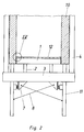
- the working and usable space is determined by a housing, the upper housing being formed by grate plates 12 and masonry 10, while the lower housing extends between side walls with supports 11 up to the grate plates 12 .
- the structure for movable grate beams 1 of the sliding grate comprises longitudinal beams 2 and running axles 6 with rollers 5 fastened thereon, which have wheel flanges and which represent the lateral guide.
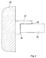
- Fig. 4 shows the detail IV of FIGS. 1 to 3, namely the masonry 10, a fixed side board 13 and a movable grate plate 12, which forms a thrust gap 15 and an edge gap 14 with the fixed side board 13.
- the gaps 14, 15 are dimensioned so that they accommodate the dimensional tolerances, thermal expansion and wear paths.
- the gap widths in this arrangement of the prior art are therefore 6 mm for the shear gap 15 and 20 mm for the edge gap 14.
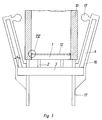
- FIG. 2 shows a sliding grate, the side members 2 of which rest on cross members 3 which are suspended from long traction elements 4.
- the upper fastenings of the tension elements 4 are not shown.
- the side guidance is done by friction plates 7. Additionally can be tensioned diagonally tension chains 8 between the supports 11 and the cross members 3.
- the sliding grate of FIG. 3 designed according to the invention has tension elements 4 set at an angle ⁇ of (here) 15 degrees.
- the angle ⁇ can vary between 3 and 45 degrees.
- the tensile forces arising in the cross member 3 take over the function of the friction plates 7 or pull chains 8.
- the tension elements 4 are firmly clamped leaf springs which are advantageously arranged in a package and which deform as a result of the pushing movement, both the pushing gap 15 and the edge gap 14 are independent of wear .
- the thrust gap 15 and the edge gap 14 are, for example, only 2 mm each in this construction and maintain this quality without the influence of wearing components of the movable supporting structure.
- the edge and shear gaps thus have the same order of magnitude as the air openings in the area of the grate plates 12 when the grate is constructed as a resistance grate according to EP-A-0 167 658.
- Fig. 3 also shows protuberances 16 of the lower housing, in which the tension elements 4 are arranged, and the connection of these protuberances to an air supply line 17. As a result, the tension elements 4 are in the cold air flow. This also eliminates changes in length of the tension elements, which could occur due to thermal expansion at different temperatures of the masonry 10 or due to heat build-up from the lower housing.
Description
- Die Erfindung betrifft eine Schubrost-Einrichtung zur Wärmebehandlung von unsbesondere feinkörnigen Schüttgütern, umfassend ein oberes und ein unteres, unter dem Druck des Kühlmediums stehendes Gehäuse, eine Mehrzahl von quer zu einer vorbestimmten Förderrichtung des Schüttguts mindestens teilweise beweglich sowie einander schuppenartig überlappend angeordneten Rostreihen, ein Tragwerk aus Längsträgern und Querträgern für die beweglich angeordneten Rostreihen sowie langgestreckte Zugelemente zur Aufhängung des Tragwerks, und befaßt sich in allgemeiner Weise mit der Seitenführung solcher Schubroste sowie vor allem deren Verbesserung.
- Bei in der Praxis üblichen Schubrosten ist das Tragwerk entweder auf Laufrollen und Laufachsen oder auf Drehachsen mit Laufringen zur Aufnahme der Förderbewegung gelagert. Aufgrund der sich dabei ergebenden, weiter unten beschriebenen Verschleißprobleme wurde ein Rost der ein gangs beschriebenen Art zum Einsatz gebracht, bei dem das Tragwerk an langen, zur senkrechten Rostlängsebene parallelen Zugelementen aufgehängt ist. Obwohl damit das Verschleißproblem der Laufrollen bzw. Laufringe beseitigt werden konnte, wurde diese Lösung unter anderem wegen Problemen in der Seitenführung des Tragwerks wieder verlassen.
- Allgemein besteht das Tragwerk solcher Schubroste aus Längsträgern, die miteinander durch die beweglichen Rostreihen selbst sowie durch weitere Streben zu einem Gesamtrahmen versteift sind. Zur Förderung des Schüttgutes führt dieser sogenannte Schübe aus, von denen der Begriff "Schubrost" herrührt. Es handelt sich um 3 bis 30 Schübe in der Minute von meist 70 bis 150 mm Länge abgestimmt auf die Länge der Überlappung der Rostplatten der aufeinanderfolgenden Rostreihen. Die Schübe werden durch mechanische Kurbeln oder hydraulische Zylinder erzeugt und auf den Rahmen geleitet.
- Entweder erfolgt die Seitenführung des Rahmens durch Spurkränze an den Laufrollen, die auf fest verlegten Schienenstücken abrollen, bzw. umgekehrt durch Schienenstücke an den Längsträgern, die auf mit Spurkränzen versehenen Rollen vor- und zurücklaufen. Oder die Querträger erhalten bei ihrer Aufhängung an langen Zugelementen an ihrer Unterseite Platten aus Stahl, die auf fest angeordneten Gegenplatten reiben.
- Diese auf dem Prinzip des Formschlusses beruhenden Lösungen zur Seitenführung der Schubroste mittels Spurkränzen bzw. Reibplatten sind verschleißbehaftet und erfordern eine Vorgabe dieses Verschleißweges in den Randspalten der beweglichen Rostreihen. Diese Vorgaben addieren sich zu den Vorgaben für die Wärmedehnung der Rostträger und führen zu entsprechend weiten, offenen Randspalten.
- Nach dem Stand der Technik liegt die Güte eines Schubrostes in seinem Widerstand gegen die Durchgasbarkeit zur Erzielung einer gleichmäßigen Durchgasung im zu behandelnden Schüttgut (s. K. von Wedel und R. Wagner "Sind Kühlroste Klinkerkühler oder Wärmerekuperatoren?", Zement-Kalk-Gips, 37. Jahrgang, Nr. 5/1984, S. 244-247). Dieser Widerstand kann durch entsprechend feine und gleichmäßig verteilte Öffnungen in dem Rostboden erzielt werden. Zu diesem Zweck ist ein als Widerstandsrost zu bezeichnender Rost bekannt geworden (EP-A-0 167 658), bei dem als wesentliche Bauelemente kastenartige Rostplatten sowie Hohlträger als Rostträger vorgesehen sind. Einen erheblichen Einfluß haben dabei jedoch die nicht zu vermeidenden Randspalte zwischen festen Seitenbordplatten und den Rostplatten beweglicher Rostreihen, wie natürlich auch der Verschleiß das verfahrenstechnische Verhalten eines solchen Widerstandsrostes wie auch von Schubrosten anderer Bauart beeinträchtigen kann.
- Schubroste leiden allgemein unter einer Randgängigkeit sowohl für das Gas als auch für das Gut. Bei Kühlrosten für Zementklinker führt die Randgängigkeit der Kühlluft zu Verschleiß am seitlichen Mauerwerk durch Sandstrahleffekte. Die Begrenzung der Lebensdauer der Schubroste durch Verschleiß geht häufig von den Randspalten aus, besonders dann, wenn nach Verschleiß der Spurkränze der Laufrollen bzw. der Reibplatten aus Stahl die formschlüssige Seitenführung auf einer Seite des Rostes auf einen Reibschluß zwischen festem Seitenbord und beweglicher Rostplatte übergeht. Einseitig ist dieser Reibschluß wegen ungleichmäßiger Einleitung der Schübe in den Rahmen oder ungleichmäßiger Gegenkräfte aus dem Schüttgut. In dem Maße, in dem die reibende Werkstoffpaarung verschleißt, wird die gegenüberliegende Seite randgängiger.
- Wird der Schwingrahmen von je einem hydraulischen Zylinder auf jeder Seite des Rostes angetrieben, kann die ungleiche Krafteinleitung ohne komplizierte Regeleinrichtungen zur Kraftverteilung auf die Zylinder so groß werden, daß nur einer der beiden Zylinder die Schubarbeit leistet, während der andere Zylinder ohne Druck mitläuft. Da bei freier Verteilung des Ölstroms auf die beiden Zylinder nur jener mit den geringeren Gegenkräften die Arbeit leistet, muß die Reibung aus der Seitenführung über den Rahmen von der gegenüberliegenden Zylinderkraft aufgebracht werden. Wegen der begrenzten Steifigkeit des Rahmens wirken deshalb besonders große Kräfte einseitig auf die Seitenführung des Rostes.
- Der Erfindung liegt die Aufgabe zugrunde, die Randspalte von Schubrosten so dicht auszubilden, daß sie den Güteanforderungen an einen Widerstandsrost entsprechen. Außerdem hat die Erfindung zum Ziel, durch die Ausbildung von Schubrosten sicherzustellen, daß sich das verfahrenstechnische Verhalten nicht durch Verschleiß verschlechtern kann, und zwar in der Erkenntnis, daß dieses nicht unwesentlich von sich verändernden Randspalten und nebenbei auch von den Schubspalten abhängt und deshalb eine verschleißbehaftete Lösung nicht zulässig ist.
- Erfindungsgemäß wird diese Aufgabe bei einem Schubrost der eingangs beschriebenen Art durch Zugelemente gelöst, die gegen die senkrechte Rostlängsebene einen Anstellwinkel von mehr als 3 Grad bilden. In Abhängigkeit von dem Anstellwinkel entstehen aus dem Eigengewicht des Rostes nach dem Parallelogramm der Kräfte in dem Querträger horizontale Zugkräfte, die sich bei mittiger Ruhelage gegenseitig aufheben. Bei Abweichung aus der Mittellage entsteht ein ungleiches Kräftepaar, dessen resultierende Kraft als Zentrierkraft seitwärts gerichteten Störkräften aus der Schubbewegung entgegenwirkt. Je nach Anstellwinkel wirkt bereits bei geringen Auslenkungen aus der Mittellage eine so große Zentrierkraft auf den beweglichen Rost, daß er nur durch Kräfte und ohne reibenden Formschluß seitlich geführt wird. Dadurch wird es u.a. auch möglich, bei einem sogenannten Widerstandsrost (EP-A-O 167 658) die flachen Schubspalte oberhalb der beweglichen Rostreihen zu den festen Rostreihen bzw. festen Seitenborden und die senkrechten Randspalte zwischen beweglichen Rostreihen und festen Seitenborden auf Dauer ebenfalls eng einzustellen und damit dessen Funktion über die Zeit weiter zu verbessern.
- In vorteilhafter Weiterbildung der Erfindung können die schräg angestellten Zugelemente als fest eingespannte und quer zur Förderrichtung angeordnete Blattfedern ausgebildet sein. Während sich die Blattfedern in Schubrichtung leicht verformen, bilden sie in Querrichtung dazu zusammen mit den Querträgern ein formsteifes System. Die Kräfte aus dieser Formsteifigkeit addieren sich zu den Querkräften aus der Schrägstellung der Zugelemente, wodurch der Schwingrahmen zusätzlich mittig geführt wird. Die Krafte zur Seitenführung sind insgesamt so groß, daß ein - wie oben beschrieben - einseitig wirkender Hydraulikantrieb zulässig wäre.
- Nach einer weiteren Ausbildung der Erfindung können die Zugelemente in schrägen, gasdicht ausgebildeten Ausstülpungen des unteren Gehäuses angeordnet sein. Das untere Gehäuse nimmt mit diesen Ausstülpungen eine ungewöhnliche Form an. Indem man die Ausstülpungen aber gemäß einer weiteren Ausbildungsform der Erfindung als Kanäle für die Zufuhr des Kühlmediums zum unteren Gehäuse ausbildet, lassen sich zumindest einige der üblichen Ventilatoren für das Kühlmedium vorteilhaft auf der meist über dem Schubrost befindlichen Ofenbühne aufstellen. Der Vorteil im Sinne der Aufgabenstellung besteht dann darin, daß die Zugelemente im Zustrom des Kühlmediums angeordnet sind. Dadurch können in besonders günstiger Weise Temperatureinflüsse durch das heiße Schüttgut und dadurch verursachte Längenänderungen der Zugelemente ausgeschlossen werden.
- Weitere Vorteile und Ausführungsformen oder -möglichkeiten der Erfindung gehen aus der folgenden Beschreibung der in den schematischen und untereinander nicht maßstäblich getreuen Zeichnungen dargestellten Ausführungsbeispiele hervor. Es zeigt
- Fig. 1
- einen Querschnitt durch einen Schubrost nach dem Stand der Technik,
- Fig. 2
- einen Querschnitt durch einen anderen Schubrost nach dem Stand der Technik,
- Fig. 3
- einen Querschnitt durch einen erfindungsgemäßen Schubrost und
- Fig. 4
- im Detail gemäß IV der Fig. 1 bis 3 eine im Maßstab vergrößerte Darstellung der Spaltverhältnisse im Seitenwandbereich der Roste.
- Bei dem in Fig. 1 dargestellten Schubrost bekannter Bauart ist der Arbeits- und Nutzraum durch ein Gehäuse bestimmt, wobei das obere Gehäuse durch Rostplatten 12 und Mauerwerk 10 gebildet wird, während sich das untere Gehäuse zwischen Seitenwänden mit Stützen 11 bis zu den Rostplatten 12 erstreckt. Das Tragwerk für bewegliche Rostträger 1 des Schubrostes umfaßt Längsträger 2 sowie Laufachsen 6 mit darauf befestigten Laufrollen 5, die Spurkränze aufweisen und die Seitenführung darstellen. Fig. 4 zeigt das Detail IV der Fig. 1 bis 3, nämlich das Mauerwerk 10, einen festen Seitenbord 13 und eine bewegliche Rostplatte 12, die mit dem festen Seitenbord 13 einen Schubspalt 15 und einen Randspalt 14 bildet. Die Spalte 14, 15 sind so bemessen, daß sie die Maßtoleranzen, Wärmedehnung und Verschleißwege aufnehmen. Die Spaltweiten betragen daher bei dieser Anordnung des Standes der Technik 6 mm für den Schubspalt 15 und 20 mm für den Randspalt 14.
- Demgegenüber stellt die bekannte Ausführung der Fig. 2 bereits eine Verbesserung dar. Sie zeigt einen Schubrost, dessen Längsträger 2 auf Querträgern 3 ruhen, die an langen Zugelementen 4 aufgehängt sind. Die oberen Befestigungen der Zugelemente 4 sind nicht dargestellt. Die Seitenführung geschieht durch Reibplatten 7. Zusätzlich können diagonal Zugketten 8 zwischen den Stützen 11 und den Querträgern 3 gespannt sein.
- Der erfindungsgemäß ausgebildete Schubrost der Fig. 3 weist im Unterschied dazu unter einem Winkel α von (hier) 15 Grad angestellte Zugelemente 4 auf. Je nach den gewünschten Kraftverhältnissen sowie entsprechend Gewicht und Abmessungen kann der Winkel α zwischen 3 und 45 Grad variieren. Die im Querträger 3 entstehenden Zugkräfte übernehmen die Funktion der Reibplatten 7 bzw. Zugketten 8. Durch Ausbildung der Zugelemente 4 als fest eingespannte, vorteilhaft in Paketform angeordnete Blattfedern, die sich infolge der Schubbewegung verformen, sind sowohl der Schubspalt 15 als auch der Randspalt 14 verschleißunabhängig. Der Schubspalt 15 und der Randspalt 14 betragen bei dieser Konstruktion beispielsweise nur noch je 2 mm und behalten diese Güte ohne Einfluß von schleißenden Bauelementen des beweglichen Tragwerks bei. Damit erreichen die Rand- und Schubspalte die gleiche Größenordnung wie die Luftöffnungen im Bereich der Rostplatten 12 bei Aufbau des Rostes als Widerstandsrost gemäß EP-A-0 167 658.
- Fig. 3 zeigt weiterhin Ausstülpungen 16 des unteren Gehäuses, in denen die Zugelemente 4 angeordnet sind, und den Anschluß dieser Ausstülpungen an eine Luftzufuhrleitung 17. Dadurch befinden sich die Zugelemente 4 im kalten Luftstrom. Damit sind auch Längenänderungen der Zugelemente ausgeschaltet, die sich durch Wärmedehnungen bei unterschiedlicher Temperatur des Mauerwerks 10 oder durch Stauwärme aus dem unteren Gehäuse einstellen könnten.
Claims (4)
- Schubrost-Einrichtung zur Wärmebehandlung von insbesondere feinkörnigen Schüttgütern mita) ein oberes und ein unteres, unter dem Druck des Kühlmediums stehendes Gehäuse,b) eine Mehrzahl von quer zu einer vorbestimmten Förderrichtung des Schüttguts mindestens teilweise beweglich sowie einander schuppenartig überlappend angeordneten Rostreihen,c) ein Tragwerk aus Längsträgern und Querträgern für die beweglich angeordneten Rostreihen undd) langgestreckte Zugelemente zur Aufhängung des Tragwerks,
dadurch gekennzeichnet, daße) die Zugelemente (4) zu der senkrechten Rostlängsebene in einem Anstellwinkel (α) von mehr als 3 Grad angeordnet sind. - Einrichtung gemäß Anspruch 1, dadurch gekennzeichnet, daß die Zugelemente (4) als fest eingespannte und quer zur Förderrichtung angeordnete Blattfedern ausgebildet sind.
- Einrichtung nach einem der Ansprüche 1 oder 2, dadurch gekennzeichnet, daß die Zugelemente (4) in schrägen, gasdicht ausgebildeten Ausstülpungen (16) des unteren Gehäuses angeordnet sind.
- Einrichtung gemäß Anspruch 3, dadurch gekennzeichnet, daß die Ausstülpungen (16) als Kanäle für die Zufuhr des Kühlmediums zum unteren Gehäuse ausgebildet sind.
Priority Applications (1)
| Application Number | Priority Date | Filing Date | Title |
|---|---|---|---|
| AT89123308T ATE88264T1 (de) | 1988-12-30 | 1989-12-16 | Schubrost-einrichtung zur waermebehandlung von schuettguetern. |
Applications Claiming Priority (2)
| Application Number | Priority Date | Filing Date | Title |
|---|---|---|---|
| DE3844493A DE3844493C1 (de) | 1988-12-30 | 1988-12-30 | |
| DE3844493 | 1988-12-30 |
Publications (3)
| Publication Number | Publication Date |
|---|---|
| EP0378821A2 EP0378821A2 (de) | 1990-07-25 |
| EP0378821A3 EP0378821A3 (de) | 1991-05-08 |
| EP0378821B1 true EP0378821B1 (de) | 1993-04-14 |
Family
ID=6370638
Family Applications (1)
| Application Number | Title | Priority Date | Filing Date |
|---|---|---|---|
| EP89123308A Expired - Lifetime EP0378821B1 (de) | 1988-12-30 | 1989-12-16 | Schubrost-Einrichtung zur Wärmebehandlung von Schüttgütern |
Country Status (10)
| Country | Link |
|---|---|
| US (1) | US4966548A (de) |
| EP (1) | EP0378821B1 (de) |
| JP (1) | JP2707343B2 (de) |
| KR (1) | KR0144578B1 (de) |
| AT (1) | ATE88264T1 (de) |
| CS (1) | CS275776B6 (de) |
| DD (1) | DD291136A5 (de) |
| DE (2) | DE3844493C1 (de) |
| DK (1) | DK167329B1 (de) |
| ES (1) | ES2039824T3 (de) |
Families Citing this family (13)
| Publication number | Priority date | Publication date | Assignee | Title |
|---|---|---|---|---|
| DE4136934C2 (de) * | 1991-11-11 | 2001-03-29 | Deutz Ag | Schubrostkühler zum Abkühlen von heißem Gut |
| DE4320725A1 (de) * | 1993-06-23 | 1995-01-05 | Kloeckner Humboldt Deutz Ag | Schubrostkühler zum Abkühlen von heißem Gut |
| DK171924B1 (da) * | 1993-10-06 | 1997-08-11 | Smidth & Co As F L | Ristkøler |
| FR2748552B1 (fr) * | 1996-05-13 | 1998-06-05 | Gec Alsthom Stein Ind | Grille d'incineration de dechets menagers |
| DE19633969A1 (de) * | 1996-08-22 | 1998-02-26 | Karl Von Wedel | Schüttgutrost |
| WO1998040683A1 (de) * | 1997-03-13 | 1998-09-17 | Bmh Claudius Peters Ag | Lagervorrichtung für den beweglichen teil eines kühl- oder feuerungsrosts |
| DE19906262A1 (de) * | 1999-02-15 | 2000-08-17 | Krupp Polysius Ag | Rostvorrichtung |
| DE59906789D1 (de) | 1999-11-09 | 2003-10-02 | Peters Claudius Tech Gmbh | Schubrost mit Seitenführungsorganen für den bewegten Rostteil |
| ATE303562T1 (de) * | 2002-09-07 | 2005-09-15 | Müllverbrennungsanlage mit einem verbrennungsrost | |
| DE102007019530C5 (de) * | 2007-04-25 | 2018-01-04 | Alite Gmbh | Verfahren und Einrichtung zum Kühlen einer auf einem Förderrost liegenden Schüttgutschicht |
| DE102008056468B3 (de) * | 2008-11-04 | 2010-04-29 | Fuguma Gmbh Maschinenbau Und Kraftwerkstechnik | Rostplattenschubrost für Verbrennungsanlagen |
| DE102012009511B4 (de) * | 2012-05-14 | 2013-12-19 | Outotec Oyj | Rostwagen zur Aufnahme von Schüttgut |
| CN108981404A (zh) * | 2018-08-27 | 2018-12-11 | 莱芜钢铁集团有限公司 | 一种烧结环冷机回转框架的调圆方法 |
Family Cites Families (7)
| Publication number | Priority date | Publication date | Assignee | Title |
|---|---|---|---|---|
| US2764403A (en) * | 1954-10-21 | 1956-09-25 | William M Duncan | Pallets and grate bar therefor |
| GB842507A (en) * | 1957-04-09 | 1960-07-27 | Fuller Co | Horizontal heat-exchange apparatus |
| US3358385A (en) * | 1965-04-12 | 1967-12-19 | Fuller Co | Reciprocating grate conveyor with side wall damage preventing means |
| DE2658489C2 (de) * | 1976-12-23 | 1983-12-22 | Ludwig Riedhammer GmbH & Co KG, 8500 Nürnberg | Ofen zum Sintern magnetkeramischer Werkstoffe |
| DE2930406A1 (de) * | 1979-07-26 | 1981-02-12 | Krupp Polysius Ag | Schubrost |
| DE3131514C1 (de) * | 1981-08-08 | 1988-09-08 | Karl von Dipl.-Ing. Dipl.-Wirtsch.-Ing. 3057 Neustadt Wedel | Verfahren zum Kuehlen von Kuehlgutbetten und Stauvorrichtung zur Durchfuehrung des Verfahrens |
| DE3332592C1 (de) * | 1983-09-08 | 1985-05-15 | Karl von Dipl.-Ing. Dipl.-Wirtsch.-Ing. 3057 Neustadt Wedel | Aus Rostelementen zusammengesetzter Rostboden fuer Schuettgueter,wie Zementklinker |
-
1988
- 1988-12-30 DE DE3844493A patent/DE3844493C1/de not_active Expired - Lifetime
-
1989
- 1989-12-16 ES ES198989123308T patent/ES2039824T3/es not_active Expired - Lifetime
- 1989-12-16 AT AT89123308T patent/ATE88264T1/de not_active IP Right Cessation
- 1989-12-16 EP EP89123308A patent/EP0378821B1/de not_active Expired - Lifetime
- 1989-12-16 DE DE8989123308T patent/DE58904080D1/de not_active Expired - Fee Related
- 1989-12-22 US US07/454,970 patent/US4966548A/en not_active Expired - Lifetime
- 1989-12-22 DK DK663889A patent/DK167329B1/da not_active IP Right Cessation
- 1989-12-28 CS CS897485A patent/CS275776B6/cs unknown
- 1989-12-28 DD DD89336611A patent/DD291136A5/de not_active IP Right Cessation
- 1989-12-29 JP JP1344987A patent/JP2707343B2/ja not_active Expired - Fee Related
- 1989-12-30 KR KR1019890020664A patent/KR0144578B1/ko not_active IP Right Cessation
Also Published As
| Publication number | Publication date |
|---|---|
| CS275776B6 (en) | 1992-03-18 |
| DK663889A (da) | 1990-07-01 |
| KR0144578B1 (ko) | 1998-08-17 |
| ES2039824T3 (es) | 1993-10-01 |
| KR900010301A (ko) | 1990-07-07 |
| DE58904080D1 (de) | 1993-05-19 |
| DD291136A5 (de) | 1991-06-20 |
| JPH02272296A (ja) | 1990-11-07 |
| EP0378821A3 (de) | 1991-05-08 |
| DK167329B1 (da) | 1993-10-11 |
| ATE88264T1 (de) | 1993-04-15 |
| DE3844493C1 (de) | 1990-08-23 |
| JP2707343B2 (ja) | 1998-01-28 |
| DK663889D0 (da) | 1989-12-22 |
| US4966548A (en) | 1990-10-30 |
| EP0378821A2 (de) | 1990-07-25 |
Similar Documents
| Publication | Publication Date | Title |
|---|---|---|
| EP0378821B1 (de) | Schubrost-Einrichtung zur Wärmebehandlung von Schüttgütern | |
| EP1743131B1 (de) | Schüttgutkühler zum kühlen von heissem kühlgut | |
| EP2161236A2 (de) | Regalbediengerät mit einem Fahrwerk | |
| DE2634104A1 (de) | Leitungswagen zum fuehren von kabeln u.dgl. | |
| EP0007464B1 (de) | Hubplattenofen | |
| EP1704005A1 (de) | Giessmaschine | |
| EP3037250A2 (de) | Maschinenrahmen für eine rollenpresse | |
| DE2604611A1 (de) | Stufenrostkuehler, insbesondere vorschub-stufenrostkuehler | |
| DE3739452C1 (de) | Koksofentuer mit keramischem Schildaufbau | |
| EP3171117A1 (de) | Regenerativer wärmeübertrager mit verbessertem dichtrahmen | |
| DE102017101544A1 (de) | Tragelement für einen Tunnelofenwagen oder -schlitten, Tunnelofenwagen oder -schlitten mit derartigen Tragelementen sowie Tunnelofen mit einem derartigen Tunnelofenwagen oder -schlitten | |
| DE3047650C2 (de) | Vorrichtung zum Herstellen von Betonplatten | |
| EP0531859B1 (de) | Brennofen insb. für keramische Erzeugnisse | |
| DE2509872A1 (de) | Stuetz- und kuehlvorrichtung fuer stranggiessprodukte | |
| DE10133973B4 (de) | Rost und Verfahren zum Aufbau eines Rostes bestehend aus untereinander formschlüssig verbundenen Lamellenkörpern | |
| DE4136934C2 (de) | Schubrostkühler zum Abkühlen von heißem Gut | |
| DE2418553B2 (de) | Gehaeuse eines wanderrostes | |
| DE3333880A1 (de) | Vorrichtung zur steuerung der lamellenabstaende an einer ueberbrueckungsvorrichtung fuer dehnungsfugen in bruecken od. dgl. | |
| EP0244710A2 (de) | Decke für einen Glasschmelzofen oder eine Arbeitswanne | |
| DE697195C (de) | Wanderrost | |
| DE547686C (de) | Vorrichtung zum Einhalten des Profils bei Kanalofenwagen | |
| DE2035515A1 (de) | Rütteltisch oder Fertigungsbahn zur Herstellung von Stahlbetonfertigteilen | |
| DE102015106579B4 (de) | Sektionsdichtung für einen Ofen | |
| DD145301A1 (de) | Gleiteinrichtung fuer verschiebbare arbeits-und lehrgerueste | |
| WO2021028287A1 (de) | Kühler zum kühlen von schüttgut |
Legal Events
| Date | Code | Title | Description |
|---|---|---|---|
| PUAI | Public reference made under article 153(3) epc to a published international application that has entered the european phase |
Free format text: ORIGINAL CODE: 0009012 |
|
| AK | Designated contracting states |
Kind code of ref document: A2 Designated state(s): AT BE CH DE ES FR GB IT LI |
|
| 17P | Request for examination filed |
Effective date: 19901228 |
|
| PUAL | Search report despatched |
Free format text: ORIGINAL CODE: 0009013 |
|
| AK | Designated contracting states |
Kind code of ref document: A3 Designated state(s): AT BE CH DE ES FR GB IT LI |
|
| 17Q | First examination report despatched |
Effective date: 19920722 |
|
| GRAA | (expected) grant |
Free format text: ORIGINAL CODE: 0009210 |
|
| AK | Designated contracting states |
Kind code of ref document: B1 Designated state(s): AT BE CH DE ES FR GB IT LI |
|
| REF | Corresponds to: |
Ref document number: 88264 Country of ref document: AT Date of ref document: 19930415 Kind code of ref document: T |
|
| REF | Corresponds to: |
Ref document number: 58904080 Country of ref document: DE Date of ref document: 19930519 |
|
| ITF | It: translation for a ep patent filed |
Owner name: LENZI & C. |
|
| GBT | Gb: translation of ep patent filed (gb section 77(6)(a)/1977) |
Effective date: 19930623 |
|
| ET | Fr: translation filed | ||
| REG | Reference to a national code |
Ref country code: ES Ref legal event code: FG2A Ref document number: 2039824 Country of ref document: ES Kind code of ref document: T3 |
|
| PLBE | No opposition filed within time limit |
Free format text: ORIGINAL CODE: 0009261 |
|
| STAA | Information on the status of an ep patent application or granted ep patent |
Free format text: STATUS: NO OPPOSITION FILED WITHIN TIME LIMIT |
|
| 26N | No opposition filed | ||
| ITTA | It: last paid annual fee | ||
| REG | Reference to a national code |
Ref country code: GB Ref legal event code: IF02 |
|
| PGFP | Annual fee paid to national office [announced via postgrant information from national office to epo] |
Ref country code: GB Payment date: 20021129 Year of fee payment: 14 |
|
| PGFP | Annual fee paid to national office [announced via postgrant information from national office to epo] |
Ref country code: FR Payment date: 20021217 Year of fee payment: 14 |
|
| PGFP | Annual fee paid to national office [announced via postgrant information from national office to epo] |
Ref country code: DE Payment date: 20021223 Year of fee payment: 14 Ref country code: AT Payment date: 20021223 Year of fee payment: 14 |
|
| PGFP | Annual fee paid to national office [announced via postgrant information from national office to epo] |
Ref country code: ES Payment date: 20021224 Year of fee payment: 14 Ref country code: CH Payment date: 20021224 Year of fee payment: 14 |
|
| PGFP | Annual fee paid to national office [announced via postgrant information from national office to epo] |
Ref country code: BE Payment date: 20030107 Year of fee payment: 14 |
|
| PG25 | Lapsed in a contracting state [announced via postgrant information from national office to epo] |
Ref country code: GB Free format text: LAPSE BECAUSE OF NON-PAYMENT OF DUE FEES Effective date: 20031216 Ref country code: AT Free format text: LAPSE BECAUSE OF NON-PAYMENT OF DUE FEES Effective date: 20031216 |
|
| PG25 | Lapsed in a contracting state [announced via postgrant information from national office to epo] |
Ref country code: ES Free format text: LAPSE BECAUSE OF NON-PAYMENT OF DUE FEES Effective date: 20031217 |
|
| PG25 | Lapsed in a contracting state [announced via postgrant information from national office to epo] |
Ref country code: LI Free format text: LAPSE BECAUSE OF NON-PAYMENT OF DUE FEES Effective date: 20031231 Ref country code: CH Free format text: LAPSE BECAUSE OF NON-PAYMENT OF DUE FEES Effective date: 20031231 Ref country code: BE Free format text: LAPSE BECAUSE OF NON-PAYMENT OF DUE FEES Effective date: 20031231 |
|
| BERE | Be: lapsed |
Owner name: *VON WEDEL KARL Effective date: 20031231 |
|
| PG25 | Lapsed in a contracting state [announced via postgrant information from national office to epo] |
Ref country code: DE Free format text: LAPSE BECAUSE OF NON-PAYMENT OF DUE FEES Effective date: 20040701 |
|
| GBPC | Gb: european patent ceased through non-payment of renewal fee |
Effective date: 20031216 |
|
| REG | Reference to a national code |
Ref country code: CH Ref legal event code: PL |
|
| PG25 | Lapsed in a contracting state [announced via postgrant information from national office to epo] |
Ref country code: FR Free format text: LAPSE BECAUSE OF NON-PAYMENT OF DUE FEES Effective date: 20040831 |
|
| REG | Reference to a national code |
Ref country code: FR Ref legal event code: ST |
|
| REG | Reference to a national code |
Ref country code: ES Ref legal event code: FD2A Effective date: 20031217 |
|
| PG25 | Lapsed in a contracting state [announced via postgrant information from national office to epo] |
Ref country code: IT Free format text: LAPSE BECAUSE OF NON-PAYMENT OF DUE FEES;WARNING: LAPSES OF ITALIAN PATENTS WITH EFFECTIVE DATE BEFORE 2007 MAY HAVE OCCURRED AT ANY TIME BEFORE 2007. THE CORRECT EFFECTIVE DATE MAY BE DIFFERENT FROM THE ONE RECORDED. Effective date: 20051216 |