EP0378143A2 - Dispositif de fixation magnétique pour positionner un appareil - Google Patents
Dispositif de fixation magnétique pour positionner un appareil Download PDFInfo
- Publication number
- EP0378143A2 EP0378143A2 EP90100293A EP90100293A EP0378143A2 EP 0378143 A2 EP0378143 A2 EP 0378143A2 EP 90100293 A EP90100293 A EP 90100293A EP 90100293 A EP90100293 A EP 90100293A EP 0378143 A2 EP0378143 A2 EP 0378143A2
- Authority
- EP
- European Patent Office
- Prior art keywords
- clamping device
- tension spring
- reference surface
- holding magnet
- tube
- Prior art date
- Legal status (The legal status is an assumption and is not a legal conclusion. Google has not performed a legal analysis and makes no representation as to the accuracy of the status listed.)
- Withdrawn
Links
Images

Classifications
-
- G—PHYSICS
- G01—MEASURING; TESTING
- G01B—MEASURING LENGTH, THICKNESS OR SIMILAR LINEAR DIMENSIONS; MEASURING ANGLES; MEASURING AREAS; MEASURING IRREGULARITIES OF SURFACES OR CONTOURS
- G01B5/00—Measuring arrangements characterised by the use of mechanical techniques
- G01B5/0002—Arrangements for supporting, fixing or guiding the measuring instrument or the object to be measured
Definitions
- the invention relates to a magnetic clamping device for positioning a device, in particular a measuring device relative to a reference surface.
- the object of the invention is to provide a magnetic clamping device which ensures a clear and precise positioning of a device, in particular a measuring device, for each position of the reference plane and enables its simple fine adjustment.
- the positioning or tensioning device contains a holding magnet and at least one mechanical adjusting element, for example a screw.
- the carrier of the Holding magnet contains two axially displaceable tubes, which are closed at the distal ends by an end plate. These tubes are axially displaceably mounted in a support body and connected to one another by a tension spring.
- a screw mechanism is arranged on the end plate of the upper tube, the actuator of which is connected to an articulated holder of the holding magnet via the tension spring.
- a release screw is arranged in the holding magnet perpendicular to its front surface.
- the two tubes are expediently mounted coaxially in a tube which is aligned perpendicular to the base of the support body and is firmly connected to it.
- the magnetic clamping device makes it possible to position even heavier measuring devices on a flat, magnetically active reference surface and to make fine adjustments to their position.
- the locking on the reference surface is clear and sufficient in terms of force, without additional adjustment elements.
- the attachment and adjustment of the measuring device can be done in any position of the reference surface, which is particularly advantageous when aligning and adjusting body parts of heavy rotating machines, for. B. in housings and bodies of powerful blade turbines and compressors.
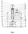
- the clamping device shown contains a support body 1 with a plate-shaped base 10. An arm 7 of a measuring device, not shown, is fastened in the support body 1 by means of a clamping screw 11 and a clamping plate 12.
- a tube 2 is fixedly connected to the base 10, in which an upper tube 21 with an upper end plate 212 is arranged. On the inside of the end plate 212 there is an upper suspension 210 and on the outside there is a chamber 213 as a rotary seat for the head 510 of a clamping screw 51.
- the tube 2 there is also a similar lower tube 22 with a base plate 222 arranged coaxially on the other
- a lower suspension 220 is provided on the inside.
- the outside of the base plate 220 is connected to a bridge 30 of a swivel mechanism 3, to which a lower bridge 31 belongs, which is connected to the upper bridge 30 via cross bolts 32 in an articulated manner.
- a holding magnet 4 with a flat functional front surface 40 is fastened to the lower bridge 31.
- a central adjusting screw 41 is screwed into the holding magnet 4, the head 42 of which is accessible from the open sides of the swivel bridge 3.
- the upper and lower suspensions 210 and 220 are connected to one another by a tension spring 5 which is surrounded by the two tubes 21 and 22.
- the clamping screw 51 engages in a threaded bore in a suspension 24 of the Tube 2 and carries at the free end a hollow actuating knob 52, the inside diameter of which is larger than the outside diameter of the tube 2.
- the adjusting mechanism 6 can advantageously consist of a known micrometer screw which carries a steel ball at its contact end.
- the magnetic clamping device described works as follows:
- the lengths of the support elements 60 are set to a value which corresponds to the desired distance of the base 10 from the functional surface 100 which is decisive for the measurement.
- the two tubes 21 and 22 are pulled together by the tension spring 5 so that their front sides 211 and 221 touch.
- the holding magnet 4 is in its upper position, there being no gap between the upper bridge 30 of the swivel mechanism 3 and the base 10.
- the adjusting screw 41 is unscrewed by means of its head 42 so that its forehead does not protrude beyond the lower front surface 40 of the holding magnet 4.
- the measuring device equipped with the magnetic clamping device according to the invention is placed on the functional surface 100 in the position determined by the length of the support elements 60. If it is necessary, ie if the measurement is to take place on the upper side of a horizontal surface, the measuring device is placed on the Functional surface 100 pressed. Then the clamping screw 51 is screwed into the suspension 24 of the tube 2 by turning the head 510. As a result, the composition of the two tubes 21 and 22 with the tension spring 5, the swivel mechanism 3 and the holding magnet 4 is shifted in the direction of arrow I according to FIG. 1 until the front surface 40 of the holding magnet 4 touches the functional surface 100 and ensures the necessary connection .
- the clamping screw 51 is turned in the opposite direction by means of the actuating rotary knob 52.
- the head 510 of the clamping screw 51 is turned in the chamber 213 of the upper cylinder 21, which moves away from the lower cylinder 22.
- the tension spring 5 is thereby tensioned until the position of the mechanism according to FIG. 2 is reached, in which the tension spring is tensioned to the maximum with simultaneous connection of the holding magnet 4 to the functional surface 100.
- the maximum tensile force of the tension spring 5 is selected so that it does not exceed the attraction force of the holding magnet 4 with a safety coefficient. This attraction is increased by the weight of the measuring device. Now the auxiliary pressure can be released and the required position of the measuring device can be adjusted or the required setting or measurement can be realized by adjusting the length of the support elements 60. Small changes in the base layer 10 and thus also in the supporting body 1 without influencing the clamping are made possible by the action of the constant force of the tension spring 5, the tensile force of which is not significantly changed by the small changes in its length as a result of small changes in the support elements 60.
- the magnetic clamping device can be used to advantage when setting and precisely positioning large rotating components and workpieces before processing or measuring them. Their use in measuring devices for determining the axes of turbo housings, compressors and gear boxes has particular advantages.
Applications Claiming Priority (2)
| Application Number | Priority Date | Filing Date | Title |
|---|---|---|---|
| CS16889A CS275977B6 (en) | 1989-01-10 | 1989-01-10 | Magnetic clamping device |
| CS168/89 | 1989-01-10 |
Publications (2)
| Publication Number | Publication Date |
|---|---|
| EP0378143A2 true EP0378143A2 (fr) | 1990-07-18 |
| EP0378143A3 EP0378143A3 (fr) | 1991-02-27 |
Family
ID=5333365
Family Applications (1)
| Application Number | Title | Priority Date | Filing Date |
|---|---|---|---|
| EP19900100293 Withdrawn EP0378143A3 (fr) | 1989-01-10 | 1990-01-08 | Dispositif de fixation magnétique pour positionner un appareil |
Country Status (2)
| Country | Link |
|---|---|
| EP (1) | EP0378143A3 (fr) |
| CS (1) | CS275977B6 (fr) |
Cited By (2)
| Publication number | Priority date | Publication date | Assignee | Title |
|---|---|---|---|---|
| WO1999057504A1 (fr) * | 1998-05-07 | 1999-11-11 | Daimlerchrysler Ag | Dispositif pour determiner la position d'un trou ou pour mesurer ce dernier |
| CN110587520A (zh) * | 2019-10-12 | 2019-12-20 | 柳州市英利机械铸造有限责任公司 | 一种空气压缩机齿轮箱加工工装 |
Families Citing this family (1)
| Publication number | Priority date | Publication date | Assignee | Title |
|---|---|---|---|---|
| CN114192426B (zh) * | 2021-12-14 | 2023-07-25 | 国光电器股份有限公司 | 一种自动检测设备 |
Citations (3)
| Publication number | Priority date | Publication date | Assignee | Title |
|---|---|---|---|---|
| US2954257A (en) * | 1958-05-19 | 1960-09-27 | Joachim A Besuch | Magnetic attachment device |
| US3769713A (en) * | 1970-11-27 | 1973-11-06 | P Norman | External can seam checking apparatus |
| GB2115157A (en) * | 1981-11-04 | 1983-09-01 | Dr David Ellsworth Newland | Caliper gauge |
-
1989
- 1989-01-10 CS CS16889A patent/CS275977B6/cs unknown
-
1990
- 1990-01-08 EP EP19900100293 patent/EP0378143A3/fr not_active Withdrawn
Patent Citations (3)
| Publication number | Priority date | Publication date | Assignee | Title |
|---|---|---|---|---|
| US2954257A (en) * | 1958-05-19 | 1960-09-27 | Joachim A Besuch | Magnetic attachment device |
| US3769713A (en) * | 1970-11-27 | 1973-11-06 | P Norman | External can seam checking apparatus |
| GB2115157A (en) * | 1981-11-04 | 1983-09-01 | Dr David Ellsworth Newland | Caliper gauge |
Cited By (3)
| Publication number | Priority date | Publication date | Assignee | Title |
|---|---|---|---|---|
| WO1999057504A1 (fr) * | 1998-05-07 | 1999-11-11 | Daimlerchrysler Ag | Dispositif pour determiner la position d'un trou ou pour mesurer ce dernier |
| CN110587520A (zh) * | 2019-10-12 | 2019-12-20 | 柳州市英利机械铸造有限责任公司 | 一种空气压缩机齿轮箱加工工装 |
| CN110587520B (zh) * | 2019-10-12 | 2024-05-07 | 柳州市英利机械铸造有限责任公司 | 一种空气压缩机齿轮箱加工工装 |
Also Published As
| Publication number | Publication date |
|---|---|
| CS8900168A2 (en) | 1991-07-16 |
| EP0378143A3 (fr) | 1991-02-27 |
| CS275977B6 (en) | 1992-03-18 |
Similar Documents
| Publication | Publication Date | Title |
|---|---|---|
| DE3100141C2 (fr) | ||
| DE3223992A1 (de) | Spannvorrichtung | |
| DE3322635C2 (fr) | ||
| DE1299980B (de) | Vorrichtung zum gegenseitigen Ausrichten zweier Werkstuecke, insbesondere Teilen der Mikroschaltungstechnik | |
| DE2030870B2 (de) | Bohrkopf, der an der drehbaren Spindel einer Werkzeugmaschine befestigt ist | |
| DE3604005A1 (de) | Spannvorrichtung zum spannen von werkstuecken auf werktischen oder werktischen von bearbeitungseinrichtungen oder -maschinen | |
| DE102011115326B4 (de) | Positioniereinrichtung für eine Presseinrichtung und Presseinrichtung | |
| DE3007261C2 (de) | Vorrichtung zum Halten von Werkstücken mit einer Bohrung | |
| EP0378143A2 (fr) | Dispositif de fixation magnétique pour positionner un appareil | |
| DE19623601B4 (de) | Tastkopf für Koordinatenmeßgeräte mit einer Klemmvorrichtung zur Klemmung des auslenkbaren Teils des Tastkopfes | |
| EP1283405B1 (fr) | Gabarit de montage pour barres de guidage linéaire | |
| DE3820085C1 (en) | Microtome, especially ultramicrotome | |
| EP0402490B1 (fr) | Manipulateur de sonde de mesure pour appareil de test de plaquette de circuit | |
| DE4424534A1 (de) | Werkzeug | |
| DE10005321A1 (de) | Vorrichtung zur schwimmenden Spannung eines zu bearbeitenden Werkstückes | |
| DE3051001C2 (de) | Spannkopf zum lösbaren Halten eines Gegenstandes | |
| EP0107763B1 (fr) | Etau, en particulier pour machine-outil | |
| DE700353C (de) | Halteeinrichtung fuer an Zusammenbau- oder Bearbeitungsvorrichtungen anzuordnende Lehrenkoerper oder lehrenhaltige Glieder | |
| DE3240662A1 (de) | Vorrichtung zur lagefixierung von werkstuecktraegern auf werkzeugmaschinen | |
| DE4321387C2 (de) | Werkstückanschlag | |
| DE1627167C3 (de) | Werkstückanschlag | |
| CH446010A (de) | Feineinstellbarer Anschlag mit elektrischem Impulsgeber | |
| DE2033390C3 (de) | Einstellvorrichtung für Werkzeuge von Drehmaschinen | |
| DE1905144B2 (de) | Abrichtvorrichtung fuer schleifscheiben zum abrichten von konkaven und konvexen profilen mit geradliniger anschlussbewegung | |
| DE301095C (fr) |
Legal Events
| Date | Code | Title | Description |
|---|---|---|---|
| PUAI | Public reference made under article 153(3) epc to a published international application that has entered the european phase |
Free format text: ORIGINAL CODE: 0009012 |
|
| AK | Designated contracting states |
Kind code of ref document: A2 Designated state(s): CH DE FR GB LI SE |
|
| PUAL | Search report despatched |
Free format text: ORIGINAL CODE: 0009013 |
|
| AK | Designated contracting states |
Kind code of ref document: A3 Designated state(s): CH DE FR GB LI SE |
|
| STAA | Information on the status of an ep patent application or granted ep patent |
Free format text: STATUS: THE APPLICATION IS DEEMED TO BE WITHDRAWN |
|
| 18D | Application deemed to be withdrawn |
Effective date: 19910828 |