EP0378143A2 - Magnetic clamping device to position an apparatus - Google Patents
Magnetic clamping device to position an apparatus Download PDFInfo
- Publication number
- EP0378143A2 EP0378143A2 EP90100293A EP90100293A EP0378143A2 EP 0378143 A2 EP0378143 A2 EP 0378143A2 EP 90100293 A EP90100293 A EP 90100293A EP 90100293 A EP90100293 A EP 90100293A EP 0378143 A2 EP0378143 A2 EP 0378143A2
- Authority
- EP
- European Patent Office
- Prior art keywords
- clamping device
- tension spring
- reference surface
- holding magnet
- tube
- Prior art date
- Legal status (The legal status is an assumption and is not a legal conclusion. Google has not performed a legal analysis and makes no representation as to the accuracy of the status listed.)
- Withdrawn
Links
Images

Classifications
-
- G—PHYSICS
- G01—MEASURING; TESTING
- G01B—MEASURING LENGTH, THICKNESS OR SIMILAR LINEAR DIMENSIONS; MEASURING ANGLES; MEASURING AREAS; MEASURING IRREGULARITIES OF SURFACES OR CONTOURS
- G01B5/00—Measuring arrangements characterised by the use of mechanical techniques
- G01B5/0002—Arrangements for supporting, fixing or guiding the measuring instrument or the object to be measured
Definitions
- the invention relates to a magnetic clamping device for positioning a device, in particular a measuring device relative to a reference surface.
- the object of the invention is to provide a magnetic clamping device which ensures a clear and precise positioning of a device, in particular a measuring device, for each position of the reference plane and enables its simple fine adjustment.
- the positioning or tensioning device contains a holding magnet and at least one mechanical adjusting element, for example a screw.
- the carrier of the Holding magnet contains two axially displaceable tubes, which are closed at the distal ends by an end plate. These tubes are axially displaceably mounted in a support body and connected to one another by a tension spring.
- a screw mechanism is arranged on the end plate of the upper tube, the actuator of which is connected to an articulated holder of the holding magnet via the tension spring.
- a release screw is arranged in the holding magnet perpendicular to its front surface.
- the two tubes are expediently mounted coaxially in a tube which is aligned perpendicular to the base of the support body and is firmly connected to it.
- the magnetic clamping device makes it possible to position even heavier measuring devices on a flat, magnetically active reference surface and to make fine adjustments to their position.
- the locking on the reference surface is clear and sufficient in terms of force, without additional adjustment elements.
- the attachment and adjustment of the measuring device can be done in any position of the reference surface, which is particularly advantageous when aligning and adjusting body parts of heavy rotating machines, for. B. in housings and bodies of powerful blade turbines and compressors.
- the clamping device shown contains a support body 1 with a plate-shaped base 10. An arm 7 of a measuring device, not shown, is fastened in the support body 1 by means of a clamping screw 11 and a clamping plate 12.
- a tube 2 is fixedly connected to the base 10, in which an upper tube 21 with an upper end plate 212 is arranged. On the inside of the end plate 212 there is an upper suspension 210 and on the outside there is a chamber 213 as a rotary seat for the head 510 of a clamping screw 51.
- the tube 2 there is also a similar lower tube 22 with a base plate 222 arranged coaxially on the other
- a lower suspension 220 is provided on the inside.
- the outside of the base plate 220 is connected to a bridge 30 of a swivel mechanism 3, to which a lower bridge 31 belongs, which is connected to the upper bridge 30 via cross bolts 32 in an articulated manner.
- a holding magnet 4 with a flat functional front surface 40 is fastened to the lower bridge 31.
- a central adjusting screw 41 is screwed into the holding magnet 4, the head 42 of which is accessible from the open sides of the swivel bridge 3.
- the upper and lower suspensions 210 and 220 are connected to one another by a tension spring 5 which is surrounded by the two tubes 21 and 22.
- the clamping screw 51 engages in a threaded bore in a suspension 24 of the Tube 2 and carries at the free end a hollow actuating knob 52, the inside diameter of which is larger than the outside diameter of the tube 2.
- the adjusting mechanism 6 can advantageously consist of a known micrometer screw which carries a steel ball at its contact end.
- the magnetic clamping device described works as follows:
- the lengths of the support elements 60 are set to a value which corresponds to the desired distance of the base 10 from the functional surface 100 which is decisive for the measurement.
- the two tubes 21 and 22 are pulled together by the tension spring 5 so that their front sides 211 and 221 touch.
- the holding magnet 4 is in its upper position, there being no gap between the upper bridge 30 of the swivel mechanism 3 and the base 10.
- the adjusting screw 41 is unscrewed by means of its head 42 so that its forehead does not protrude beyond the lower front surface 40 of the holding magnet 4.
- the measuring device equipped with the magnetic clamping device according to the invention is placed on the functional surface 100 in the position determined by the length of the support elements 60. If it is necessary, ie if the measurement is to take place on the upper side of a horizontal surface, the measuring device is placed on the Functional surface 100 pressed. Then the clamping screw 51 is screwed into the suspension 24 of the tube 2 by turning the head 510. As a result, the composition of the two tubes 21 and 22 with the tension spring 5, the swivel mechanism 3 and the holding magnet 4 is shifted in the direction of arrow I according to FIG. 1 until the front surface 40 of the holding magnet 4 touches the functional surface 100 and ensures the necessary connection .
- the clamping screw 51 is turned in the opposite direction by means of the actuating rotary knob 52.
- the head 510 of the clamping screw 51 is turned in the chamber 213 of the upper cylinder 21, which moves away from the lower cylinder 22.
- the tension spring 5 is thereby tensioned until the position of the mechanism according to FIG. 2 is reached, in which the tension spring is tensioned to the maximum with simultaneous connection of the holding magnet 4 to the functional surface 100.
- the maximum tensile force of the tension spring 5 is selected so that it does not exceed the attraction force of the holding magnet 4 with a safety coefficient. This attraction is increased by the weight of the measuring device. Now the auxiliary pressure can be released and the required position of the measuring device can be adjusted or the required setting or measurement can be realized by adjusting the length of the support elements 60. Small changes in the base layer 10 and thus also in the supporting body 1 without influencing the clamping are made possible by the action of the constant force of the tension spring 5, the tensile force of which is not significantly changed by the small changes in its length as a result of small changes in the support elements 60.
- the magnetic clamping device can be used to advantage when setting and precisely positioning large rotating components and workpieces before processing or measuring them. Their use in measuring devices for determining the axes of turbo housings, compressors and gear boxes has particular advantages.
Abstract
Description
Die Erfindung betrifft eine magnetische Spannvorrichtung zur Positionierung eines Geräts, insbesondere eines Meßgeräts gegenüber einer Bezugsfläche.The invention relates to a magnetic clamping device for positioning a device, in particular a measuring device relative to a reference surface.
In der Praxis ist es häufig erforderlich, ein bestimmtes Bauteil in einer vorgegebenen Position in bezug auf eine gegebene Bezugsebene und/oder die Koordinatenachsen einer Meß- oder Werkzeugmaschine genau einzustellen. Dies gilt beispielsweise bei der Bestimmung der Achsenlage von Zylinderstopfbuchsenflächen eines geteilten Turbinen- oder Kompressorgehäuses gegenüber der Trennebene ihrer Gehäuseteile. Zu diesem Zweck wird bisher eine geeignete Meßeinrichtung an die jeweilige Trennfläche mit Hilfe von Haftmagneten befestigt. Die erforderliche Feineinstellung der Position der Meßeinrichtung muß jedoch im voraus durch ein System von Justierelementen vorgenommen werden, von denen einige an dem Gehäuseteil festgelegt werden müssen, der die jeweilige Trennebene bestimmt. Diese schwierige Einstellung kann bei vertikal verlaufender Trennebene nicht durchgeführt werden. Eine solche Ausrichtung der Gehäuse- bzw. Körperteile ist jedoch im Hinblick auf die nachfolgenden Bearbeitungsvorgänge, wie die Herstellung von zylindrischen Aussparungen, wünschenswert, die mit der Achse der vorgeformten Stopfbuchsenflächen genau konzentrisch sein sollen. Bei der Einstellung einer genauen Position während der ersten und bei der Einspannung während einer folgenden Phase wirkt sich das Gewicht der Meßeinrichtung nachteilig aus.In practice, it is often necessary to precisely set a specific component in a predetermined position in relation to a given reference plane and / or the coordinate axes of a measuring or machine tool. This applies, for example, when determining the axial position of cylinder gland surfaces of a split turbine or Compressor housing opposite the parting plane of their housing parts. For this purpose, a suitable measuring device has hitherto been attached to the respective separating surface with the aid of holding magnets. However, the required fine adjustment of the position of the measuring device must be carried out in advance by a system of adjusting elements, some of which have to be fixed on the housing part which determines the respective parting plane. This difficult setting cannot be carried out with the separating plane running vertically. Such an alignment of the housing or body parts is, however, desirable with regard to the subsequent machining operations, such as the production of cylindrical recesses, which are intended to be exactly concentric with the axis of the preformed gland surfaces. When a precise position is set during the first phase and during clamping in a subsequent phase, the weight of the measuring device has a disadvantageous effect.
Aufgabe der Erfindung ist es, eine magnetische Spannvorrichtung zu schaffen, die eine eindeutige und genaue Positionierung eines Geräts, insbesondere eines Meßgeräts, für jede Lage der Bezugsebene gewährleistet und dessen einfachere Feineinstellung ermöglicht.The object of the invention is to provide a magnetic clamping device which ensures a clear and precise positioning of a device, in particular a measuring device, for each position of the reference plane and enables its simple fine adjustment.
Diese Aufgabe wird erfindungsgemäß durch die Merkmale des Patentanspruchs 1 gelöst.This object is achieved by the features of
Die erfindungsgemäße Positionier- oder Spannvorrichtung enthält einen Haltemagnet und mindestens ein mechanisches Stellelement, zum Beispiel eine Schraube. Der Träger des Haltemagnetes enthält zwei gegeneinander axial verschiebbare Rohre, die an den entfernten Enden durch je eine Endplatte abgeschlossen sind. Diese Rohre sind in einem Tragkörper axial verschiebbar gelagert und durch eine Zugfeder miteinander verbunden. An der Endplatte des oberen Rohrs ist ein Schraubenmechanismus angeordnet, dessen Stellglied über die Zugfeder mit einer gelenkigen Halterung des Haftmagneten verbunden ist. Im Haltemagnet ist senkrecht zu seiner Frontfläche eine Löseschraube angeordnet.The positioning or tensioning device according to the invention contains a holding magnet and at least one mechanical adjusting element, for example a screw. The carrier of the Holding magnet contains two axially displaceable tubes, which are closed at the distal ends by an end plate. These tubes are axially displaceably mounted in a support body and connected to one another by a tension spring. A screw mechanism is arranged on the end plate of the upper tube, the actuator of which is connected to an articulated holder of the holding magnet via the tension spring. A release screw is arranged in the holding magnet perpendicular to its front surface.
Zweckmäßig sind die beiden Rohre gleichachsig in einem Tubus gelagert, welcher senkrecht zur Basis des Tragkörpers ausgerichtet und mit diesem fest verbunden ist.The two tubes are expediently mounted coaxially in a tube which is aligned perpendicular to the base of the support body and is firmly connected to it.
Die magnetische Spanneinrichtung gemäß der Erfindung ermöglicht, auch schwerere Meßvorrichtungen an einer ebenen, magnetisch aktiven Bezugsfläche zu positionieren und Feineinstellungen ihrer Lage vorzunehmen. Die Arretierung auf der Bezugsfläche ist eindeutig und kräftemäßig ausreichend, und zwar ohne zusätzliche Justierelemente. Die Befestigung und Justierung des Meßgeräts kann in beliebiger Lage der Bezugsfläche erfolgen, was sich besonders bei der Ausrichtung und Einstellung von Körperteilen schwerer rotierender Maschinen vorteilhaft auswirkt, z. B. bei Gehäusen und Körpern von leistungsfähigen Schaufelturbinen und Kompressoren.The magnetic clamping device according to the invention makes it possible to position even heavier measuring devices on a flat, magnetically active reference surface and to make fine adjustments to their position. The locking on the reference surface is clear and sufficient in terms of force, without additional adjustment elements. The attachment and adjustment of the measuring device can be done in any position of the reference surface, which is particularly advantageous when aligning and adjusting body parts of heavy rotating machines, for. B. in housings and bodies of powerful blade turbines and compressors.
Weitere Besonderheiten und Vorteile der Erfindung sind bei dem in der Zeichnung dargestellten Ausführungsbeispiel verwirklicht, das im folgenden ausführlicher beschrieben wird. Es zeigen:
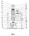
- Fig. 1 einen schematischen Axialschnitt einer Spanneinrichtung im entspannten Zustand;
- Fig. 2 die Spanneinrichtung nach Fig. 1 im gespannten Zustand.
- Figure 1 is a schematic axial section of a tensioning device in the relaxed state.
- Fig. 2 shows the tensioning device according to Fig. 1 in the tensioned state.
Die dargestellte Spanneinrichtung enthält einen Tragkörper 1 mit einer plattenförmigen Basis 10. Im Tragkörper 1 wird ein Arm 7 einer nicht dargestellten Meßvorrichtung mittels einer Spannschraube 11 und einer Klemmplatte 12 befestigt. Mit der Basis 10 ist ein Tubus 2 fest verbunden, in dem ein oberes Rohr 21 mit einer oberen Endplatte 212 angeordnet ist. An der Innenseite der Endplatte 212 ist eine obere Aufhängung 210 angeordnet und an der Außenseite befindet sich eine Kammer 213 als Drehsitz für den Kopf 510 einer Spannschraube 51. Im Tubus 2 ist ferner ein gleichartiges unteres Rohr 22 mit einer Bodenplatte 222 gleichachsig angeordnet, an deren Innenseite eine untere Aufhängung 220 vorgesehen ist. Die Außenseite der Bodenplatte 220 ist mit einer Brücke 30 eines Schwenkmechanismus 3 verbunden, zu dem eine untere Brücke 31 gehört, die mit der oberen Brücke 30 über Querbolzen 32 gelenkig verbunden ist. An der unteren Brücke 31 ist ein Haltemagnet 4 mit ebener Funktionsfrontfläche 40 befestigt. Im Haltemagnet 4 ist eine zentrale Stellschraube 41 eingeschraubt, deren Kopf 42 von den offenen Seiten der Schwenkbrücke 3 zugänglich ist. Die obere und untere Aufhängung 210 und 220 sind durch eine Zugfeder 5 miteinander verbunden, die von den beiden Rohren 21 und 22 umgeben ist. Die Spannschraube 51 greift in eine Gewindebohrung in einer Aufhängung 24 des Tubus 2 ein und trägt am freien Ende einen hohlen Betätigungsdrehknopf 52, dessen Innendurchmesser größer als der Außendurchmesser des Tubus 2 ist.The clamping device shown contains a
An der Basis 10 ist an jeder Seite des Tubus 2 ein Stellmechanismus 6 angebracht, der ein axial verschiebbares Stützglied 60 aufweist. Der Stellmechanismus 6 kann mit Vorteil aus einer bekannten Mikrometerschraube bestehen, die an ihrem Berührungsende eine Stahlkugel trägt.An
Die Arbeitsweise der beschriebenen magnetischen Spanneinrichtung ist folgende:The magnetic clamping device described works as follows:
Vor der Einspannung werden die Längen der Abstützelemente 60 auf einen Wert eingestellt, der dem gewünschten Abstand der Basis 10 von der für die Messung maßgebenden Funktionsfläche 100 entspricht. Von der Zugfeder 5 werden die beiden Rohre 21 und 22 zusammengezogen, so daß sich ihre Frontseiten 211 und 221 berühren. Der Haltemagnet 4 befindet sich in seiner oberen Stellung, wobei zwischen der oberen Brücke 30 des Schwenkmechanismus 3 und der Basis 10 keine Lücke vorliegt. Die Stellschraube 41 ist mittels ihres Kopfes 42 herausgeschraubt, so daß ihre Stirn nicht über die untere Frontfläche 40 des Haltemagnets 4 hinausragt.Before the clamping, the lengths of the
Die mit der magnetischen Spanneinrichtung nach der Erfindung ausgestattete Meßvorrichtung wird an die Funktionsfläche 100 in die durch die Länge der Abstützelemente 60 bestimmte Lage angelegt. Falls es notwendig ist, d. h. wenn die Messung auf der oberen Seite einer waagerechten Fläche erfolgen soll, wird die Meßvorrichtung auf die Funktionsfläche 100 aufgedrückt. Danach wird die Spannschraube 51 durch Drehen des Kopfes 510 in die Aufhängung 24 des Tubus 2 eingeschraubt. Dadurch wird die Zusammensetzung der beiden Rohre 21 und 22 mit der Zugfeder 5, dem Schwenkmechanismus 3 und dem Haltemagnet 4 in der Pfeilrichtung I gemäß Fig. 1 so lange verschoben, bis die Frontfläche 40 des Haltemagnets 4 die Funktionsfläche 100 berührt und die notwendige Verbindung sicherstellt. Danach wird die Spannschraube 51 mittels des Betätigungsdrehknopfes 52 in umgekehrte Richtung gedreht. Der Kopf 510 der Spannschraube 51 wird in der Kammer 213 des oberen Zylinders 21 durchgedreht, der sich vom unteren Zylinder 22 entfernt. Zugleich wird dadurch die Zugfeder 5 so lange gespannt, bis die Lage des Mechanismus gemäß Fig. 2 erreicht ist, in welcher die Zugfeder maximal gespannt ist bei gleichzeitiger Verbindung des Haltemagnets 4 mit der Funktionsfläche 100.The measuring device equipped with the magnetic clamping device according to the invention is placed on the
Die maximale Zugkraft der Zugfeder 5 wird so gewählt, daß sie mit einem Sicherheitskoeffizient die Anziehungskraft des Haltemagnets 4 nicht übersteigt. Diese Anziehungskraft wird um das Gewicht des Meßgerätes vergrößert. Jetzt kann der Hilfsandruck aufgehoben werden und durch Längenverstellung der Abstützelemente 60 kann die benötigte Lage des Meßgeräts eingestellt oder die verlangte Einstellung oder Messung realisiert werden. Kleine Veränderungen der Basislage 10 und somit auch des Tragkörpers 1 ohne Beeinflussung der Einspannung werden durch Einwirkung der konstanten Kraft der Zugfeder 5 ermöglicht, deren Zugkraft durch die kleinen Veränderungen ihrer Länge als Folge kleiner Veränderungen der Abstützelemente 60 wesentlich nicht verändert wird.The maximum tensile force of the
Nach Beendigung der Arbeit genügt es, die Stellschraube 41 durch Drehen ihres Kopfes 42 im Haltemagnet 4 so weit herauszuschrauben, daß die Frontfläche 40 des Haltemagnets 4 von der Funktionsfläche 100 abgehoben wird. Nach dem Abheben zieht sich die Zugfeder auf ihre ursprüngliche Länge zusammen und das System nimmt wieder die in der Fig. 1 dargestellte Ausgangslage ein.After completion of the work, it is sufficient to unscrew the
Die magnetische Spanneinrichtung kann vorteilhaft bei der Einstellung und genauen Positionierung von großen rotierenden Bauteilen und Werkstücken vor ihrer Bearbeitung bzw. Vermessung eingesetzt werden. Besondere Vorteile bringt ihre Anwendung bei Meßvorrichtungen zur Bestimmung der Achsen von Turbogehäusen, Kompressoren und Getriebekästen.The magnetic clamping device can be used to advantage when setting and precisely positioning large rotating components and workpieces before processing or measuring them. Their use in measuring devices for determining the axes of turbo housings, compressors and gear boxes has particular advantages.
- 1 Tragkörper1 supporting body
- 10 Basis10 base
- 11 Spannschraube11 clamping screw
- 12 Lasche12 tab
- 100 Bezugsfläche100 reference surface
- 2 Tubus2 tubes
- 21 Oberes Rohr21 Upper tube
- 210 Obere Aufhängung210 Upper suspension
- 211 Stirnseite211 end face
- 212 Endplatte212 end plate
- 213 Kammer213 chamber
- 22 Unteres Rohr22 Lower tube
- 220 Untere Aufhängung220 Lower suspension
- 221 Untere Stirnseite221 Lower end face
- 222 Bodenplatte222 base plate
- 24 Verschluß24 closure
- 3 Schwenkmechanismus3 swivel mechanism
- 30 Obere Brücke30 Upper bridge
- 31 Untere Brücke31 Lower bridge
- 32 Bolzen32 bolts
- 4 Haftmagnet4 holding magnet
- 40 Frontfläche40 front surface
- 41 Gewindebolzen41 threaded bolts
- 42 Kopf42 head
- 43 Stirn43 forehead
- 5 Zugfeder5 tension spring
- 50 Spannmechanismus50 clamping mechanism
- 51 Spannschraube51 clamping screw
- 510 Kopf510 head
- 52 Betätigungsdrehknopf52 control knob
- 6 Stellmechanismus6 adjusting mechanism
- 60 Stützstreben60 support struts
- 7 Arm7 arm
Claims (6)
dadurch gekennzeichnet,
daß die Tragkonstruktion einen über längenverstellbare Stützstreben (60) auf der Bezugsfläche (100) abgestützten Tragkörper (1) aufweist, und
daß der über ein Schwenklager (30, 31, 32) und eine längsgeführte Zugfeder (5) am Tragkörper (1) gehalterte Haftmagnet (4) mittels einer Verstellvorrichtung (50) aus einer abgehobenen Ruhelage in eine auf der Bezugsfläche (100) aufliegende Haftstellung bewegbar ist.1. Magnetic clamping device for precise positioning of a machine element, in particular a measuring device, in relation to a reference surface, consisting of a support bracket for at least one component of the machine element, a holding magnet and at least one mechanical actuator,
characterized,
that the support structure has a support body (1) which is supported by length-adjustable support struts (60) on the reference surface (100), and
that the holding magnet (4), which is held by a swivel bearing (30, 31, 32) and a longitudinal tension spring (5) on the supporting body (1), can be moved by means of an adjusting device (50) from a raised rest position into a holding position lying on the reference surface (100) is.
dadurch gekennzeichnet,
daß die Zugfeder (6) von zwei gleichachsigen längsgeführten Rohren (21, 22) umgeben ist, von denen das obere Rohr (21) mit der Verstellvorrichtung (50) zur Längsbewegung der Zugfeder (5) und das untere Rohr (22) mit dem Schwenklager (30, 31, 32) verbunden ist.2. Clamping device according to claim 1,
characterized,
that the tension spring (6) is surrounded by two coaxial longitudinal tubes (21, 22), of which the upper tube (21) with the adjusting device (50) for the longitudinal movement of the tension spring (5) and the lower tube (22) with the pivot bearing (30, 31, 32) is connected.
dadurch gekennzeichnet,
daß die beiden Rohre (21, 22) in einer am Tragkörper (1) befestigten Führung (2) angeordnet sind.3. Clamping device according to claim 2,
characterized,
that the two tubes (21, 22) are arranged in a guide (2) fastened to the supporting body (1).
dadurch gekennzeichnet,
daß das Schwenklager mindestens zwei bügelförmige Brücken (30, 31) enthält, die über Zapfen (32) miteinander schwenkbar verbunden sind.4. Clamping device according to one of claims 1 to 3,
characterized,
that the pivot bearing contains at least two bow-shaped bridges (30, 31) which are pivotally connected to one another via pins (32).
dadurch gekennzeichnet,
daß an der Endplatte (212) des oberen Rohrs (21) ein das obere Ende der Zugfeder (5) halternder Kopf (210) festgelegt ist, der mit einer Stellschraube (51) des Verstellmechanismus (50) verbunden ist.5. Clamping device according to one of claims 1 to 4,
characterized,
that on the end plate (212) of the upper tube (21) an upper end of the tension spring (5) holding head (210) is fixed, which is connected to an adjusting screw (51) of the adjusting mechanism (50).
dadurch gekennzeichnet,
daß im Haftmagneten (4) ein gegen die Bezugsfläche (100) ausschraubbarer Gewindebolzen (41) mit einem zwischen den Brücken (30, 31) befindlichen Drehkopf (42) angeordnet ist.6. Clamping device according to one of claims 1 to 5,
characterized,
that a threaded bolt (41), which can be unscrewed against the reference surface (100) and has a rotary head (42) located between the bridges (30, 31), is arranged in the holding magnet (4).
Applications Claiming Priority (2)
| Application Number | Priority Date | Filing Date | Title |
|---|---|---|---|
| CS168/89 | 1989-01-10 | ||
| CS16889A CS275977B6 (en) | 1989-01-10 | 1989-01-10 | Magnetic clamping device |
Publications (2)
| Publication Number | Publication Date |
|---|---|
| EP0378143A2 true EP0378143A2 (en) | 1990-07-18 |
| EP0378143A3 EP0378143A3 (en) | 1991-02-27 |
Family
ID=5333365
Family Applications (1)
| Application Number | Title | Priority Date | Filing Date |
|---|---|---|---|
| EP19900100293 Withdrawn EP0378143A3 (en) | 1989-01-10 | 1990-01-08 | Magnetic clamping device to position an apparatus |
Country Status (2)
| Country | Link |
|---|---|
| EP (1) | EP0378143A3 (en) |
| CS (1) | CS275977B6 (en) |
Cited By (2)
| Publication number | Priority date | Publication date | Assignee | Title |
|---|---|---|---|---|
| WO1999057504A1 (en) * | 1998-05-07 | 1999-11-11 | Daimlerchrysler Ag | Device for determining the position or size of a hole |
| CN110587520A (en) * | 2019-10-12 | 2019-12-20 | 柳州市英利机械铸造有限责任公司 | Air compressor gear box processing frock |
Families Citing this family (1)
| Publication number | Priority date | Publication date | Assignee | Title |
|---|---|---|---|---|
| CN114192426B (en) * | 2021-12-14 | 2023-07-25 | 国光电器股份有限公司 | Automatic detection equipment |
Citations (3)
| Publication number | Priority date | Publication date | Assignee | Title |
|---|---|---|---|---|
| US2954257A (en) * | 1958-05-19 | 1960-09-27 | Joachim A Besuch | Magnetic attachment device |
| US3769713A (en) * | 1970-11-27 | 1973-11-06 | P Norman | External can seam checking apparatus |
| GB2115157A (en) * | 1981-11-04 | 1983-09-01 | Dr David Ellsworth Newland | Caliper gauge |
-
1989
- 1989-01-10 CS CS16889A patent/CS275977B6/en unknown
-
1990
- 1990-01-08 EP EP19900100293 patent/EP0378143A3/en not_active Withdrawn
Patent Citations (3)
| Publication number | Priority date | Publication date | Assignee | Title |
|---|---|---|---|---|
| US2954257A (en) * | 1958-05-19 | 1960-09-27 | Joachim A Besuch | Magnetic attachment device |
| US3769713A (en) * | 1970-11-27 | 1973-11-06 | P Norman | External can seam checking apparatus |
| GB2115157A (en) * | 1981-11-04 | 1983-09-01 | Dr David Ellsworth Newland | Caliper gauge |
Cited By (2)
| Publication number | Priority date | Publication date | Assignee | Title |
|---|---|---|---|---|
| WO1999057504A1 (en) * | 1998-05-07 | 1999-11-11 | Daimlerchrysler Ag | Device for determining the position or size of a hole |
| CN110587520A (en) * | 2019-10-12 | 2019-12-20 | 柳州市英利机械铸造有限责任公司 | Air compressor gear box processing frock |
Also Published As
| Publication number | Publication date |
|---|---|
| EP0378143A3 (en) | 1991-02-27 |
| CS275977B6 (en) | 1992-03-18 |
| CS8900168A2 (en) | 1991-07-16 |
Similar Documents
| Publication | Publication Date | Title |
|---|---|---|
| DE3100141C2 (en) | ||
| DE3322635C2 (en) | ||
| DE102015114212A1 (en) | Arrangement for clamping a rotatable workpiece | |
| DE2030870B2 (en) | Drill head attached to the rotatable spindle of a machine tool | |
| DE3604005A1 (en) | CLAMPING DEVICE FOR CLAMPING WORKPIECES ON WORK TABLES OR WORK TABLES OF MACHINING DEVICES OR MACHINES | |
| DE102011115326B4 (en) | Positioning device for a pressing device and pressing device | |
| DE3007261C2 (en) | Device for holding workpieces with a bore | |
| EP0378143A2 (en) | Magnetic clamping device to position an apparatus | |
| DE19623601B4 (en) | Probe for coordinate measuring with a clamping device for clamping the deflectable part of the probe | |
| EP1283405B1 (en) | Mounting template for linear guide rails | |
| DE3820085C1 (en) | Microtome, especially ultramicrotome | |
| EP0402490B1 (en) | Measuring-probe manipulator for a wafer-testing device | |
| DE4424534A1 (en) | Tool | |
| DE10005321A1 (en) | Floating clamp for workpiece consists o f two clamping pistons and clamping jaws, collet chuck of two tensioning levers and fixed attachment | |
| DE3051001C2 (en) | Clamping head for releasably holding an object | |
| EP0107763B1 (en) | Vice, in particular a machine tool vice | |
| DE10248204A1 (en) | Device for gripping and clamping object, especially for micro-manufacturing, has electrorheological or magnetorheological liquid container through which controllable electric or magnetic field passes | |
| DE3240662A1 (en) | DEVICE FOR FIXING THE POSITION OF WORKPIECE CARRIERS ON MACHINE TOOLS | |
| DE4321387C2 (en) | Workpiece stop | |
| DE1627167C3 (en) | Workpiece stop | |
| DE2033390C3 (en) | Adjustment device for tools of lathes | |
| EP3412411B1 (en) | Tensioning system | |
| DE1905144B2 (en) | DRESSING DEVICE FOR GRINDING WHEELS FOR DRESSING CONCAVES AND CONVEX PROFILES WITH STRAIGHT CONNECTION MOVEMENT | |
| DE301095C (en) | ||
| DE1286777C2 (en) | Holder for microscope stage |
Legal Events
| Date | Code | Title | Description |
|---|---|---|---|
| PUAI | Public reference made under article 153(3) epc to a published international application that has entered the european phase |
Free format text: ORIGINAL CODE: 0009012 |
|
| AK | Designated contracting states |
Kind code of ref document: A2 Designated state(s): CH DE FR GB LI SE |
|
| PUAL | Search report despatched |
Free format text: ORIGINAL CODE: 0009013 |
|
| AK | Designated contracting states |
Kind code of ref document: A3 Designated state(s): CH DE FR GB LI SE |
|
| STAA | Information on the status of an ep patent application or granted ep patent |
Free format text: STATUS: THE APPLICATION IS DEEMED TO BE WITHDRAWN |
|
| 18D | Application deemed to be withdrawn |
Effective date: 19910828 |