EP0373020B1 - Gegen-Elektrode für elektrochrome Vorrichtungen - Google Patents
Gegen-Elektrode für elektrochrome Vorrichtungen Download PDFInfo
- Publication number
- EP0373020B1 EP0373020B1 EP89403180A EP89403180A EP0373020B1 EP 0373020 B1 EP0373020 B1 EP 0373020B1 EP 89403180 A EP89403180 A EP 89403180A EP 89403180 A EP89403180 A EP 89403180A EP 0373020 B1 EP0373020 B1 EP 0373020B1
- Authority
- EP
- European Patent Office
- Prior art keywords
- electrochromic system
- electrochromic
- lithium
- nickel oxide
- layer
- Prior art date
- Legal status (The legal status is an assumption and is not a legal conclusion. Google has not performed a legal analysis and makes no representation as to the accuracy of the status listed.)
- Expired - Lifetime
Links
- GNRSAWUEBMWBQH-UHFFFAOYSA-N oxonickel Chemical compound [Ni]=O GNRSAWUEBMWBQH-UHFFFAOYSA-N 0.000 claims abstract description 44
- 229910000480 nickel oxide Inorganic materials 0.000 claims abstract description 42
- WHXSMMKQMYFTQS-UHFFFAOYSA-N Lithium Chemical compound [Li] WHXSMMKQMYFTQS-UHFFFAOYSA-N 0.000 claims abstract description 16
- 229910052744 lithium Inorganic materials 0.000 claims abstract description 16
- 239000000463 material Substances 0.000 claims abstract description 10
- 239000001257 hydrogen Substances 0.000 claims abstract description 9
- 229910052739 hydrogen Inorganic materials 0.000 claims abstract description 9
- 238000004544 sputter deposition Methods 0.000 claims abstract description 5
- PXHVJJICTQNCMI-UHFFFAOYSA-N Nickel Chemical compound [Ni] PXHVJJICTQNCMI-UHFFFAOYSA-N 0.000 claims description 46
- 229910001416 lithium ion Inorganic materials 0.000 claims description 20
- 238000003780 insertion Methods 0.000 claims description 19
- 230000037431 insertion Effects 0.000 claims description 19
- HBBGRARXTFLTSG-UHFFFAOYSA-N Lithium ion Chemical compound [Li+] HBBGRARXTFLTSG-UHFFFAOYSA-N 0.000 claims description 16
- ZNOKGRXACCSDPY-UHFFFAOYSA-N tungsten trioxide Chemical compound O=[W](=O)=O ZNOKGRXACCSDPY-UHFFFAOYSA-N 0.000 claims description 14
- 239000004020 conductor Substances 0.000 claims description 11
- 238000000151 deposition Methods 0.000 claims description 10
- 229910052759 nickel Inorganic materials 0.000 claims description 10
- 230000008021 deposition Effects 0.000 claims description 9
- -1 titanium alkoxide Chemical class 0.000 claims description 8
- 239000011521 glass Substances 0.000 claims description 7
- 230000003647 oxidation Effects 0.000 claims description 7
- 238000007254 oxidation reaction Methods 0.000 claims description 7
- MHCFAGZWMAWTNR-UHFFFAOYSA-M lithium perchlorate Chemical compound [Li+].[O-]Cl(=O)(=O)=O MHCFAGZWMAWTNR-UHFFFAOYSA-M 0.000 claims description 6
- 229910001486 lithium perchlorate Inorganic materials 0.000 claims description 6
- 239000000758 substrate Substances 0.000 claims description 6
- 229920003171 Poly (ethylene oxide) Polymers 0.000 claims description 4
- RUOJZAUFBMNUDX-UHFFFAOYSA-N propylene carbonate Chemical compound CC1COC(=O)O1 RUOJZAUFBMNUDX-UHFFFAOYSA-N 0.000 claims description 4
- 230000005291 magnetic effect Effects 0.000 claims description 3
- 239000010936 titanium Substances 0.000 claims description 3
- 229910052719 titanium Inorganic materials 0.000 claims description 3
- UFHFLCQGNIYNRP-UHFFFAOYSA-N Hydrogen Chemical compound [H][H] UFHFLCQGNIYNRP-UHFFFAOYSA-N 0.000 claims description 2
- 239000006104 solid solution Substances 0.000 claims description 2
- 239000000243 solution Substances 0.000 claims description 2
- 238000006713 insertion reaction Methods 0.000 claims 2
- 150000002815 nickel Chemical group 0.000 claims 1
- 125000004430 oxygen atom Chemical group O* 0.000 claims 1
- 229910000314 transition metal oxide Inorganic materials 0.000 claims 1
- 239000003792 electrolyte Substances 0.000 abstract description 6
- 125000004435 hydrogen atom Chemical group [H]* 0.000 abstract 1
- 239000010416 ion conductor Substances 0.000 abstract 1
- 230000005540 biological transmission Effects 0.000 description 10
- 150000002500 ions Chemical class 0.000 description 9
- KWYUFKZDYYNOTN-UHFFFAOYSA-M Potassium hydroxide Chemical compound [OH-].[K+] KWYUFKZDYYNOTN-UHFFFAOYSA-M 0.000 description 7
- 238000004040 coloring Methods 0.000 description 7
- 238000004458 analytical method Methods 0.000 description 6
- 239000001301 oxygen Substances 0.000 description 6
- 229910052760 oxygen Inorganic materials 0.000 description 6
- QVGXLLKOCUKJST-UHFFFAOYSA-N atomic oxygen Chemical compound [O] QVGXLLKOCUKJST-UHFFFAOYSA-N 0.000 description 5
- 238000006243 chemical reaction Methods 0.000 description 5
- 238000002845 discoloration Methods 0.000 description 5
- 238000004949 mass spectrometry Methods 0.000 description 5
- QGLKJKCYBOYXKC-UHFFFAOYSA-N nonaoxidotritungsten Chemical compound O=[W]1(=O)O[W](=O)(=O)O[W](=O)(=O)O1 QGLKJKCYBOYXKC-UHFFFAOYSA-N 0.000 description 5
- 229910001930 tungsten oxide Inorganic materials 0.000 description 5
- 238000005546 reactive sputtering Methods 0.000 description 4
- ATJFFYVFTNAWJD-UHFFFAOYSA-N Tin Chemical compound [Sn] ATJFFYVFTNAWJD-UHFFFAOYSA-N 0.000 description 3
- 230000009471 action Effects 0.000 description 3
- 229940075397 calomel Drugs 0.000 description 3
- ZOMNIUBKTOKEHS-UHFFFAOYSA-L dimercury dichloride Chemical compound Cl[Hg][Hg]Cl ZOMNIUBKTOKEHS-UHFFFAOYSA-L 0.000 description 3
- 229910003437 indium oxide Inorganic materials 0.000 description 3
- PJXISJQVUVHSOJ-UHFFFAOYSA-N indium(iii) oxide Chemical compound [O-2].[O-2].[O-2].[In+3].[In+3] PJXISJQVUVHSOJ-UHFFFAOYSA-N 0.000 description 3
- 238000000034 method Methods 0.000 description 3
- 230000002441 reversible effect Effects 0.000 description 3
- 238000010301 surface-oxidation reaction Methods 0.000 description 3
- QAOWNCQODCNURD-UHFFFAOYSA-N Sulfuric acid Chemical compound OS(O)(=O)=O QAOWNCQODCNURD-UHFFFAOYSA-N 0.000 description 2
- 230000032683 aging Effects 0.000 description 2
- 230000015556 catabolic process Effects 0.000 description 2
- 230000001351 cycling effect Effects 0.000 description 2
- 238000006731 degradation reaction Methods 0.000 description 2
- 239000010408 film Substances 0.000 description 2
- 230000006870 function Effects 0.000 description 2
- 238000004519 manufacturing process Methods 0.000 description 2
- 239000000203 mixture Substances 0.000 description 2
- 230000004044 response Effects 0.000 description 2
- 239000005368 silicate glass Substances 0.000 description 2
- 229910052723 transition metal Inorganic materials 0.000 description 2
- 150000003624 transition metals Chemical class 0.000 description 2
- XLYOFNOQVPJJNP-UHFFFAOYSA-N water Substances O XLYOFNOQVPJJNP-UHFFFAOYSA-N 0.000 description 2
- 238000004566 IR spectroscopy Methods 0.000 description 1
- VEQPNABPJHWNSG-UHFFFAOYSA-N Nickel(2+) Chemical compound [Ni+2] VEQPNABPJHWNSG-UHFFFAOYSA-N 0.000 description 1
- BQCADISMDOOEFD-UHFFFAOYSA-N Silver Chemical compound [Ag] BQCADISMDOOEFD-UHFFFAOYSA-N 0.000 description 1
- 239000002253 acid Substances 0.000 description 1
- 230000002378 acidificating effect Effects 0.000 description 1
- 239000000853 adhesive Substances 0.000 description 1
- 230000001070 adhesive effect Effects 0.000 description 1
- 239000003513 alkali Substances 0.000 description 1
- XKRFYHLGVUSROY-UHFFFAOYSA-N argon Substances [Ar] XKRFYHLGVUSROY-UHFFFAOYSA-N 0.000 description 1
- 229910052786 argon Inorganic materials 0.000 description 1
- 230000015572 biosynthetic process Effects 0.000 description 1
- 238000004061 bleaching Methods 0.000 description 1
- 230000008859 change Effects 0.000 description 1
- 239000002322 conducting polymer Substances 0.000 description 1
- 229920001940 conductive polymer Polymers 0.000 description 1
- 125000004122 cyclic group Chemical group 0.000 description 1
- 230000007423 decrease Effects 0.000 description 1
- 230000007547 defect Effects 0.000 description 1
- 238000009792 diffusion process Methods 0.000 description 1
- 238000001035 drying Methods 0.000 description 1
- 238000003487 electrochemical reaction Methods 0.000 description 1
- 230000005294 ferromagnetic effect Effects 0.000 description 1
- 238000009472 formulation Methods 0.000 description 1
- 239000007789 gas Substances 0.000 description 1
- 230000036571 hydration Effects 0.000 description 1
- 238000006703 hydration reaction Methods 0.000 description 1
- 125000002887 hydroxy group Chemical group [H]O* 0.000 description 1
- 230000006872 improvement Effects 0.000 description 1
- 229910001449 indium ion Inorganic materials 0.000 description 1
- 239000007788 liquid Substances 0.000 description 1
- 239000006193 liquid solution Substances 0.000 description 1
- 229910003002 lithium salt Inorganic materials 0.000 description 1
- 159000000002 lithium salts Chemical class 0.000 description 1
- 239000000178 monomer Substances 0.000 description 1
- 229910001453 nickel ion Inorganic materials 0.000 description 1
- BFDHFSHZJLFAMC-UHFFFAOYSA-L nickel(ii) hydroxide Chemical compound [OH-].[OH-].[Ni+2] BFDHFSHZJLFAMC-UHFFFAOYSA-L 0.000 description 1
- 229920000620 organic polymer Polymers 0.000 description 1
- 230000001590 oxidative effect Effects 0.000 description 1
- 230000010287 polarization Effects 0.000 description 1
- 229920000642 polymer Polymers 0.000 description 1
- 229940072033 potash Drugs 0.000 description 1
- BWHMMNNQKKPAPP-UHFFFAOYSA-L potassium carbonate Substances [K+].[K+].[O-]C([O-])=O BWHMMNNQKKPAPP-UHFFFAOYSA-L 0.000 description 1
- 235000015320 potassium carbonate Nutrition 0.000 description 1
- 239000000843 powder Substances 0.000 description 1
- 238000002360 preparation method Methods 0.000 description 1
- 239000012078 proton-conducting electrolyte Substances 0.000 description 1
- 230000009467 reduction Effects 0.000 description 1
- 229910052709 silver Inorganic materials 0.000 description 1
- 239000004332 silver Substances 0.000 description 1
- 238000010186 staining Methods 0.000 description 1
- 238000006467 substitution reaction Methods 0.000 description 1
- 238000002207 thermal evaporation Methods 0.000 description 1
- 239000010409 thin film Substances 0.000 description 1
- WFKWXMTUELFFGS-UHFFFAOYSA-N tungsten Chemical compound [W] WFKWXMTUELFFGS-UHFFFAOYSA-N 0.000 description 1
- 229910052721 tungsten Inorganic materials 0.000 description 1
- 239000010937 tungsten Substances 0.000 description 1
- 238000009827 uniform distribution Methods 0.000 description 1
- 125000000391 vinyl group Chemical group [H]C([*])=C([H])[H] 0.000 description 1
- 229920002554 vinyl polymer Polymers 0.000 description 1
- 238000004832 voltammetry Methods 0.000 description 1
Images
Classifications
-
- G—PHYSICS
- G02—OPTICS
- G02F—OPTICAL DEVICES OR ARRANGEMENTS FOR THE CONTROL OF LIGHT BY MODIFICATION OF THE OPTICAL PROPERTIES OF THE MEDIA OF THE ELEMENTS INVOLVED THEREIN; NON-LINEAR OPTICS; FREQUENCY-CHANGING OF LIGHT; OPTICAL LOGIC ELEMENTS; OPTICAL ANALOGUE/DIGITAL CONVERTERS
- G02F1/00—Devices or arrangements for the control of the intensity, colour, phase, polarisation or direction of light arriving from an independent light source, e.g. switching, gating or modulating; Non-linear optics
- G02F1/01—Devices or arrangements for the control of the intensity, colour, phase, polarisation or direction of light arriving from an independent light source, e.g. switching, gating or modulating; Non-linear optics for the control of the intensity, phase, polarisation or colour
- G02F1/17—Devices or arrangements for the control of the intensity, colour, phase, polarisation or direction of light arriving from an independent light source, e.g. switching, gating or modulating; Non-linear optics for the control of the intensity, phase, polarisation or colour based on variable-absorption elements not provided for in groups G02F1/015 - G02F1/169
-
- G—PHYSICS
- G02—OPTICS
- G02F—OPTICAL DEVICES OR ARRANGEMENTS FOR THE CONTROL OF LIGHT BY MODIFICATION OF THE OPTICAL PROPERTIES OF THE MEDIA OF THE ELEMENTS INVOLVED THEREIN; NON-LINEAR OPTICS; FREQUENCY-CHANGING OF LIGHT; OPTICAL LOGIC ELEMENTS; OPTICAL ANALOGUE/DIGITAL CONVERTERS
- G02F1/00—Devices or arrangements for the control of the intensity, colour, phase, polarisation or direction of light arriving from an independent light source, e.g. switching, gating or modulating; Non-linear optics
- G02F1/01—Devices or arrangements for the control of the intensity, colour, phase, polarisation or direction of light arriving from an independent light source, e.g. switching, gating or modulating; Non-linear optics for the control of the intensity, phase, polarisation or colour
- G02F1/15—Devices or arrangements for the control of the intensity, colour, phase, polarisation or direction of light arriving from an independent light source, e.g. switching, gating or modulating; Non-linear optics for the control of the intensity, phase, polarisation or colour based on an electrochromic effect
- G02F1/153—Constructional details
- G02F1/155—Electrodes
-
- G—PHYSICS
- G02—OPTICS
- G02F—OPTICAL DEVICES OR ARRANGEMENTS FOR THE CONTROL OF LIGHT BY MODIFICATION OF THE OPTICAL PROPERTIES OF THE MEDIA OF THE ELEMENTS INVOLVED THEREIN; NON-LINEAR OPTICS; FREQUENCY-CHANGING OF LIGHT; OPTICAL LOGIC ELEMENTS; OPTICAL ANALOGUE/DIGITAL CONVERTERS
- G02F1/00—Devices or arrangements for the control of the intensity, colour, phase, polarisation or direction of light arriving from an independent light source, e.g. switching, gating or modulating; Non-linear optics
- G02F1/01—Devices or arrangements for the control of the intensity, colour, phase, polarisation or direction of light arriving from an independent light source, e.g. switching, gating or modulating; Non-linear optics for the control of the intensity, phase, polarisation or colour
- G02F1/15—Devices or arrangements for the control of the intensity, colour, phase, polarisation or direction of light arriving from an independent light source, e.g. switching, gating or modulating; Non-linear optics for the control of the intensity, phase, polarisation or colour based on an electrochromic effect
- G02F1/1514—Devices or arrangements for the control of the intensity, colour, phase, polarisation or direction of light arriving from an independent light source, e.g. switching, gating or modulating; Non-linear optics for the control of the intensity, phase, polarisation or colour based on an electrochromic effect characterised by the electrochromic material, e.g. by the electrodeposited material
- G02F1/1523—Devices or arrangements for the control of the intensity, colour, phase, polarisation or direction of light arriving from an independent light source, e.g. switching, gating or modulating; Non-linear optics for the control of the intensity, phase, polarisation or colour based on an electrochromic effect characterised by the electrochromic material, e.g. by the electrodeposited material comprising inorganic material
- G02F1/1524—Transition metal compounds
Definitions
- the present invention relates to electrochromic systems and more specifically to a counter-electrode which can be used in particular for an electrochromic glazing unit operating in transmission or in reflection, the color change of which is due to the reversible insertion of lithium ions into a layer of trioxide of tungsten.
- Glazing or other electrochromic systems are systems whose color is changed under the action of a difference in electrical potential.
- the electrochromic character is obtained thanks to a layer of an oxide of a transition metal, in particular a layer of tungsten oxide placed between two layers conducting the electric current, an electrolytic layer being interposed between the electrochromic layer and one of the two conductive layers.
- electrolytes Most of the ion-conducting materials in the first column of the MENDELEIEV table are suitable as electrolytes. Thus, electrochromic systems have been described using sulfuric acid or any other strong acid placed in contact with a layer of tungsten oxide. However, the major drawback of proton conducting electrolytes is their acidic nature which, if special precautions are not taken, leads to the rapid degradation of the other layers of the system whose longevity is therefore extremely short.
- lithium electrolytes are more particularly preferred because of the high diffusion rate of lithium ions, particularly in tungsten trioxide which allows rapid coloring and discoloration of the system.
- the technical problem which then arises is to find a suitable material for the counter-electrode, that is to say perfectly compatible with the electrolyte used, not decomposing under the action of the electric current and especially not having coloring - or in the discolored state when the layer of electrochromic material is itself in the discolored state - this last condition being essential for the production of a glazing operating in transmission likely for example to be used as glazing of building.
- the invention more specifically has for its object an electrochromic glazing according to claim 1 capable of operating in transmission comprising a transparent substrate, in particular made of glass coated with a transparent electroconductive layer, of a layer of an electrochromic material formed of an oxide d a transition metal, in particular of tungsten trioxide, of a layer of an ionic conductive material with lithium, of a counter-electrode and of a second conductive layer preferably also transparent.
- the counter-electrode according to the invention consists of a layer of nickel oxide.
- the authors of the present invention have found, as shown in the tests below, that the insertion of lithium ions is perfectly reversible possible in such a layer of nickel oxide. For reasons indicated later, it is preferably carried out with a hydrated nickel oxide, for example prepared under the conditions explained below.
- nickel oxide is a material capable of inserting and releasing lithium ions under the action of a difference in electrical potential.
- the electrochromism observed is advantageously of the anodic type while the tungsten oxide is a material with cathodic electrochromism, in other words it is the discoloration - and not the coloration - which is observed when lithium ions are inserted in a layer d nickel oxide.
- a nickel oxide counter electrode Associated with a tungsten oxide layer, a nickel oxide counter electrode therefore gives a significant improvement in contrast.
- the cycle is also possible with lithium ions and not protons and can be schematized as follows:
- reaction No. 2 which relates to the highest current densities. If a permanently discolored counter electrode is desired - this for example to avoid any interference in the colorings, it is preferable to use reaction n ° 4, although this is not preferred because the densities of current admitted are approximately 6 times weaker than for reaction n ° 2. Equilibrium n ° 3 is probable but this assumption did not been checked.
- the equilibrium (2) is favored if one starts from an oxide in a stoichiometric O / Ni ratio preferably close to 1.60.
- the layers will preferably be left in an oxidizing atmosphere for as short a time as possible after their preparation and before the insertion of lithium ions, this in order to avoid before the assembly of the system an increase in the O / Ni ratio due to the oxygen in the air.
- Ni [O] AT and Ni [O] B rather than formulas: NiO (OH) and Ni (OH) 2 when the majority nickel oxide is rather in an oxidation state + 3 or respectively + 2 in order to distinguish the two main types of hydrated nickel oxides used, but this is a language convention given that the analysis methods used practically do not allow to judge the actual state of hydration and therefore to highlight a formulation of the type: Ni (OH) x , nH2O
- the nickel oxide layer is for example deposited by reactive sputtering or any other known technique of depositing a thin film of oxide on a glass substrate.
- Ni [O] A type layer is obtained directly by reactive sputtering
- the Ni [O] B type layer is obtained by reduction in potassium hydroxide of a Ni [O] A type layer by applying a potential difference -0.6 volts with respect to a calomel reference electrode.
- the thickness of the nickel oxide layer is preferably chosen between 60 and 300 nanometers and advantageously between 80 and 100 nanometers. Too small thicknesses are not recommended due to the greater brittleness layers, while greater thicknesses lead to less transparent products in the discolored state and above all the additional insertion capacity of lithium ions then obtained is unnecessary because it exceeds the own insertion capacity of the layer tungsten oxide.
- the ionic conductive material used as the electrolyte is a liquid solution of lithium perchlorate in propylene carbonate.
- the ion-conducting material is an organic lithium-conducting polymer.
- Patent EP-A-13,199 gives examples of polymers suitable for the implementation of the invention. Good results have been more particularly obtained with a solid solution of lithium perchlorate in polyethylene oxide.
- This organic polymer also serves as an adhesive material for the assembly of laminated glazing, the first glass sheet being provided with a transparent electrically conductive layer and a layer of tungsten trioxide and the second glass sheet with a layer electrically conductive and counter electrode.
- the ionic conductive material is a lithium conductive gel obtained from a titanium alkoxide in accordance with the teachings of patent application FR-A-2,593,321.
- the nickel oxide layer is deposited by sputtering assisted by a magnetic field, operating on a thin nickel target (preferably 2 mm thick) in order to reduce its ferromagnetic character which, for a thick target, does not allow not the formation of a plasma.
- the voltage is 250 volts.
- the plasma gas is at a pressure of 3.33 Pa, with an oxygen-hydrogen ratio of 80/20.
- the deposition speed of 3.3 nanometers per minute. A layer whose thickness is approximately 80 nanometers is deposited here.
- the substrate thus prepared is placed in a solution of lithium perchlorate in propylene carbonate by passing a given quantity of current Q, then after drying the sample is analyzed by mass spectrometry of the secondary ions under a main bombardment of ions positive oxygen.
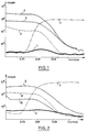
- the profile obtained is shown diagrammatically in FIG. 1 where the depth of the analysis is shown on the abscissa and the number of hits or impacts received on the ordinate; it should be noted in the first place that these curves must be considered above all as qualitative, the correlation number of strokes-quantity of an ion being very difficult to establish and that on the other hand this analytical technique and the chosen operating mode do not allow the presence of oxygen and / or hydrogen ions to be observed.
- curve 1 in thick solid lines represents the background and is not significant in the context of the invention except to define a zero level.
- Curve 2 in dashed lines corresponds to indium ions; curve 3 dotted with nickel ions and curves 4 and 5 with lithium ions, curve 4 in thin solid lines being obtained for a quantity of current Q of 10 milliCoulombs per square centimeter (10 mC / cm2) and curve 5 (small circles) for a quantity of current two times lower.
- curves 4 and 5 are parallel to curve 3, which indicates a uniform distribution of the lithium ions in the nickel oxide layer.
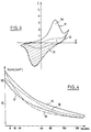
- the layers of nickel oxide just prepared are therefore layers in a metastable state, which advantageously has the maximum capacity for insertion of lithium ions (see FIG. 4), but which involves assembly of the system fairly quickly after the deposition of the nickel oxide layer to maintain this preferred low oxygen / nickel ratio.
- Ni [O] B is capable of inserting lithium.
- a layer of nickel oxide of the Ni [O] A type was prepared, under the same conditions as above and it was reduced in the potassium hydroxide by applying a voltage of -0.6 Volt relative to an electrode. of reference to calomel (equilibrium n ° 1).
- the profiles obtained by mass spectrometry of the secondary ions have been represented in FIG. 2 for which the same conventions of representation have been adopted as for FIG. 1, so that the curves 6, 7, 8.9 and 10 correspond respectively to the same elements as curves 1, 2, 3, 4 and 5.
- the general appearance of these curves is very similar of the general appearance of Figure 1 and the same conclusions therefore apply.
- the quantity of lithium inserted is much smaller than for Ni [O] A and that curve 10 presents a maximum at the surface attributed as before to an oxidation state of the surface of Ni [O] B most important.
- FIG. 4 shows the amount of current accepted by a layer of nickel oxide as a function of its residence time in air.
- the different curves correspond to different deposition conditions due to different oxygen-hydrogen ratios in the plasma. For curves 15, 16, 17 and 18 these ratios are respectively 80/20, 90/10, 70/30 and 60/40.
- the first remark is that the insertion capacity decreases sharply over time and that it is therefore preferable to seal the electrochromic cell in a brief period after the deposition of the layer of nickel oxide.
- a mass spectrometry profile by secondary ions under a main bombardment of positive argon ions while working on negative secondary oxygen ions moreover highlights an extremely rapid surface oxidation of these layers.
- curves 15 to 18 also highlights the fact that the amount of current and therefore the amount of lithium ions inserted is optimal for an oxygen-hydrogen ratio close to 80/20 at the time of deposition.
- the best results are obtained with layers deposited with a plasma without hydrogen; the initial layer being in these conditions at its maximum oxidation state.
- Ni [O] A type The intensity of the coloration of a nickel layer of the Ni [O] A type naturally depends on the thickness of this layer.
- nickel oxide layers of 60 to 180 nanometers have in the isolated state (glass + ITO + NiOLi layer) a visible transmission for all the thicknesses tested substantially identical and close to 80%.
- the light transmission varies fairly linearly depending on the thickness between a value of 45% and 18% for thicknesses of 60 and 180 nanometers respectively.
- Electrochromic cells were then prepared comprising a main electrode made of tungsten trioxide and a counter electrode made of nickel oxide of the Ni (O) A type .
- a main electrode made of tungsten trioxide and a counter electrode made of nickel oxide of the Ni (O) A type .
- a layer of indium oxide doped with tin of 350 nanometers having a square resistance of 5 Ohms was deposited on a substrate of 100 cm2 of silicate glass.
- a layer of tungsten trioxide by thermal evaporation of a tungsten trioxide powder of 320 nanometers.
- a second glass plate of the same dimensions coated with a layer of indium oxide doped with tin is provided with a layer of nickel oxide of 80 nanometers, deposited by reactive sputtering with an oxygen-hydrogen ratio in 80/20 plasma.
- the oxygen-nickel atomic ratio is 1.60. This layer of nickel oxide is discolored by insertion of lithium ions.
- the two plates thus prepared are then assembled in an autoclave by means of a 50-micron polyoxyethylene film in which lithium perchlorate is dissolved.
- the visible light transmission of the system obtained is 73%.
- the cell is placed in a hot enclosure whose temperature is 80 ° C. Staining / discoloration cycles are carried out without observing degradation, with a voltage of - 1.7 volts for coloring and + 0.7 volts for discoloration.
- the response time of the system is 1 minute, which is well suited for producing building glazing or a sunroof for a motor vehicle.
- the light transmission of the system is 32%.
- Another cell was also prepared under conditions identical in all respects to the first cell. except that the electrolytic polyoxyethylene film is replaced with a conductive lithium gel obtained from titanium alkoxide in accordance with the teachings of patent application FR-A-2,593,321.
- the present invention relates more particularly to electrochromic systems operating in transmission, but it goes without saying that it can also be applied to the production of electrochromic systems operating in reflection. For this, it suffices to insert at the rear of the system, for example between the layer of nickel oxide and the transparent conductive electrode - or in substitution of the latter - a reflective metallic layer such as a silver layer. . This system can then be used in particular for producing a day and night mirror for motor vehicles.
Landscapes
- Physics & Mathematics (AREA)
- Nonlinear Science (AREA)
- General Physics & Mathematics (AREA)
- Optics & Photonics (AREA)
- Chemical & Material Sciences (AREA)
- Inorganic Chemistry (AREA)
- Crystallography & Structural Chemistry (AREA)
- Electrochromic Elements, Electrophoresis, Or Variable Reflection Or Absorption Elements (AREA)
- Devices For Indicating Variable Information By Combining Individual Elements (AREA)
- Electrodes For Compound Or Non-Metal Manufacture (AREA)
- Electrolytic Production Of Non-Metals, Compounds, Apparatuses Therefor (AREA)
- Surface Treatment Of Glass (AREA)
Claims (13)
- Elektrochromes System, welches ein durchsichtiges Substrat, insbesondere Glas, umfaßt, das aufeinanderfolgend mit einer durchsichtigen elktrisch leitenden Schicht, einer Schicht aus elektrochromem Material, die aus einem Übergangsmatelloxid, insbesondere Wolframtrioxid, besteht, einer Schicht aus einem Lithiumionen leitenden Material, einer Gegenelektrode und einer anderen durchsichtigen elektrisch leitenden Schicht beschichtet ist, dadurch gekennzeichnet, daß die Gegenelektrode aufgrund von Einlagerungs- und Freisetzungsreaktionen der Lithiumionen elektrochrome Eigenschaften aufweist und aus einer Schicht eines Oxids des Nickels besteht, das überwiegend in der Oxidationsstufe +3 vorliegt und diese Oxidationsstufe während der Einlagerungs- und Freisetzungsreaktionen beibehalten kann, wobei das elektrochrome System derart konzipiert und zusammengebaut ist, daß die Gegenelektrode unter wasserfreien Bedingungen gehalten ist.
- Elektrochromes System nach Anspruch 1, dadurch gekenn zeichnet, daß die Nickeloxidschicht ein Verhältnis von etwa 1 Nickelatom auf 1,60 Sauerstoffatome aufweist.
- Elektrochromes System nach Anspruch 1 oder 2, dadurch gekennzeichnet, daß die Nickeloxidschicht durch Reaktionskathodenzerstäubung aufgebracht ist.
- Elektrochromes System nach Anspruch 3, dadurch gekennzeichnet, daß die Zerstäubung in Gegenwart eines wasserstoffhaltigen Plasmas durchgeführt wird.
- Elektrochromes System nach Anspruch 3 oder 4, dadurch gekennzeichnet, daß die Nickeloxidschicht durch von einem Magnetfeld gestützte Reaktionskathodenzerstäubung ausgehend von einem Target aus metallischem Nickel mit einer Dicke von etwa 2 mm aufgebracht wird.
- Elektrochromes System nach Anspruch 4 oder 5, dadurch gekennzeichnet, daß das Sauerstoff/Wasserstoff-Verhältnis im Plasma etwa 80/20 beträgt.
- Elektrochromes System nach einem der Ansprüche 1 - 6, dadurch gekennzeichnet, daß die Gegenelektrode eine Dicke zwischen 60 und 300 und vorzugsweise zwischen 80 und 100 Nanometer aufweist.
- Elektrochromes System nach einem der Ansprüche 1 - 7, dadurch gekennzeichnet, daß das Litiumionen leitende Material eine Lösung aus Lithiumperchlorat in Propylencarbonat ist.
- Elektrochromes System nach einem der Ansprüche 1 - 7, dadurch gekennzeichnet, daß das ionenleitende Material ein Lithium leitender makromolekularer Stoff ist.
- Elektrochromes System nach Anspruch 9, dadurch gekennzeichnet, daß das ionenleitende Material eine feste Lösung von Litiumperchlorat in Polyethylenoxid ist.
- Elektrochromes System nach einem der Ansprüche 1 - 7, dadurch gekennzeichnet, daß das ionenleitende Material ein Lithium leitendes Gel ist, das ausgehend von einem Titanalkoholat hergestellt wird.
- Elektrochromes System nach einem der Ansprüche 1 - 11, dadurch gekennzeichnet, daß der Zusammenbau des Systems spätestens 12 Stunden nach Aufbringen der Nickeloxidschicht erfolgt.
- Elektrochromes System nach einem der Ansprüche 1 - 12, dadurch gekennzeichnet, daß die Nickeloxidschicht vor dem Zusammenbau unter streng wasserfreien Bedingungen gehalten wird.
Applications Claiming Priority (2)
| Application Number | Priority Date | Filing Date | Title |
|---|---|---|---|
| FR8815086 | 1988-11-21 | ||
| FR8815086A FR2639441A1 (fr) | 1988-11-21 | 1988-11-21 | Contre-electrode pour systemes electrochromes |
Publications (2)
| Publication Number | Publication Date |
|---|---|
| EP0373020A1 EP0373020A1 (de) | 1990-06-13 |
| EP0373020B1 true EP0373020B1 (de) | 1994-09-07 |
Family
ID=9372020
Family Applications (1)
| Application Number | Title | Priority Date | Filing Date |
|---|---|---|---|
| EP89403180A Expired - Lifetime EP0373020B1 (de) | 1988-11-21 | 1989-11-20 | Gegen-Elektrode für elektrochrome Vorrichtungen |
Country Status (10)
| Country | Link |
|---|---|
| US (1) | US5164855A (de) |
| EP (1) | EP0373020B1 (de) |
| JP (1) | JPH02199429A (de) |
| KR (1) | KR900008315A (de) |
| AT (1) | ATE111237T1 (de) |
| BR (1) | BR8905853A (de) |
| CA (1) | CA2003386A1 (de) |
| DE (1) | DE68918063T2 (de) |
| ES (1) | ES2063155T3 (de) |
| FR (1) | FR2639441A1 (de) |
Cited By (1)
| Publication number | Priority date | Publication date | Assignee | Title |
|---|---|---|---|---|
| US9581875B2 (en) | 2005-02-23 | 2017-02-28 | Sage Electrochromics, Inc. | Electrochromic devices and methods |
Families Citing this family (16)
| Publication number | Priority date | Publication date | Assignee | Title |
|---|---|---|---|---|
| US5086351A (en) * | 1989-07-13 | 1992-02-04 | M&T Chemicals, Inc. | Electrochromic elements, materials for use in such element, processes for making such elements and such materials and use of such element in an electrochromic glass device |
| US5274493A (en) * | 1989-07-13 | 1993-12-28 | Elf Atochem North America, Inc. | Electrochromic element, materials for use in such element, processes for making such element and such materials and use of such element in an electrochromic glass device |
| US5352504A (en) * | 1990-11-14 | 1994-10-04 | Saint-Gobain Vitrage International | Electrochromic glazing |
| FR2690536B1 (fr) * | 1992-04-28 | 1994-06-17 | Saint Gobain Vitrage Int | Vitrage electrochrome. |
| US5643369A (en) * | 1993-06-24 | 1997-07-01 | Fuji Xerox Co., Ltd. | Photoelectric conversion element having an infrared transmissive indium-tin oxide film |
| JP2961236B2 (ja) * | 1995-02-15 | 1999-10-12 | 工業技術院長 | 酸化ニッケル系エレクトロクロミック材料の製造方法 |
| EP0770900A1 (de) | 1995-10-26 | 1997-05-02 | Saint-Gobain Vitrage | Elektrochrome Verglasung |
| DE19824127A1 (de) * | 1998-05-29 | 1999-12-02 | Bayer Ag | Elektrochrome Anordnung auf Basis von Poly-(3,4-ethylendioxy-thiophen)-Derivaten in Kombination mit einer Gegenelektrode, die Metalloxide aus der VI. oder VIII. Nebengruppe enthält |
| FR2793888B1 (fr) * | 1999-05-20 | 2002-06-28 | Saint Gobain Vitrage | Dispositif electrochimique |
| US7042615B2 (en) * | 2002-05-17 | 2006-05-09 | The Regents Of The University Of California | Electrochromic devices based on lithium insertion |
| US9782949B2 (en) | 2008-05-30 | 2017-10-10 | Corning Incorporated | Glass laminated articles and layered articles |
| US7715082B2 (en) * | 2008-06-30 | 2010-05-11 | Soladigm, Inc. | Electrochromic devices based on lithium insertion |
| US9664974B2 (en) | 2009-03-31 | 2017-05-30 | View, Inc. | Fabrication of low defectivity electrochromic devices |
| US8525019B2 (en) | 2010-07-01 | 2013-09-03 | Primestar Solar, Inc. | Thin film article and method for forming a reduced conductive area in transparent conductive films for photovoltaic modules |
| KR20220120709A (ko) | 2011-12-12 | 2022-08-30 | 뷰, 인크. | 박막 디바이스 및 제조 |
| CN109491172B (zh) * | 2018-12-27 | 2021-06-18 | 中国建筑材料科学研究总院有限公司 | 电致变色器件的离子传导层材料筛选方法 |
Citations (1)
| Publication number | Priority date | Publication date | Assignee | Title |
|---|---|---|---|---|
| EP0253713A1 (de) * | 1986-07-04 | 1988-01-20 | Saint-Gobain Vitrage | Elektrochromes Fensterglas mit variabler Transmission |
Family Cites Families (9)
| Publication number | Priority date | Publication date | Assignee | Title |
|---|---|---|---|---|
| FR2442512A1 (fr) * | 1978-11-22 | 1980-06-20 | Anvar | Nouveaux materiaux elastomeres a conduction ionique |
| JPS59102216A (ja) * | 1982-12-06 | 1984-06-13 | Canon Inc | 全固体型エレクトロクロミツク素子の製造方法 |
| JPS6028630A (ja) * | 1983-07-27 | 1985-02-13 | Nippon Kogaku Kk <Nikon> | リチウムイオンを利用するエレクトロクロミツク表示素子 |
| US4761061A (en) * | 1985-09-19 | 1988-08-02 | Asahi Glass Company Ltd. | Method for fabrication of electrochromic device and the same fabricated by the method |
| FR2593321B1 (fr) * | 1986-01-23 | 1990-11-16 | Giers | Materiau conducteur ionique utilisable comme electrolyte solide de type gel |
| US4805996A (en) * | 1986-12-18 | 1989-02-21 | Ford Motor Company | Electrochromic optical shutter |
| DE3643690A1 (de) * | 1986-12-20 | 1988-07-07 | Dornier System Gmbh | Steuerbare scheibe |
| SE8801637D0 (sv) * | 1988-04-29 | 1988-04-29 | Jim Stevens | Electrochromic device and a method to manufacture the same |
| US4923289A (en) * | 1988-10-05 | 1990-05-08 | Ford Motor Company | Electrochromic devices having a gradient of color intensities |
-
1988
- 1988-11-21 FR FR8815086A patent/FR2639441A1/fr active Granted
-
1989
- 1989-11-17 US US07/438,566 patent/US5164855A/en not_active Expired - Fee Related
- 1989-11-20 DE DE68918063T patent/DE68918063T2/de not_active Expired - Fee Related
- 1989-11-20 JP JP1299876A patent/JPH02199429A/ja active Pending
- 1989-11-20 ES ES89403180T patent/ES2063155T3/es not_active Expired - Lifetime
- 1989-11-20 CA CA002003386A patent/CA2003386A1/fr not_active Abandoned
- 1989-11-20 EP EP89403180A patent/EP0373020B1/de not_active Expired - Lifetime
- 1989-11-20 AT AT89403180T patent/ATE111237T1/de not_active IP Right Cessation
- 1989-11-21 KR KR1019890016873A patent/KR900008315A/ko not_active Application Discontinuation
- 1989-11-21 BR BR898905853A patent/BR8905853A/pt not_active IP Right Cessation
Patent Citations (1)
| Publication number | Priority date | Publication date | Assignee | Title |
|---|---|---|---|---|
| EP0253713A1 (de) * | 1986-07-04 | 1988-01-20 | Saint-Gobain Vitrage | Elektrochromes Fensterglas mit variabler Transmission |
Cited By (3)
| Publication number | Priority date | Publication date | Assignee | Title |
|---|---|---|---|---|
| US9581875B2 (en) | 2005-02-23 | 2017-02-28 | Sage Electrochromics, Inc. | Electrochromic devices and methods |
| US10061174B2 (en) | 2005-02-23 | 2018-08-28 | Sage Electrochromics, Inc. | Electrochromic devices and methods |
| US11567383B2 (en) | 2005-02-23 | 2023-01-31 | Sage Electrochromics, Inc. | Electrochromic devices and methods |
Also Published As
| Publication number | Publication date |
|---|---|
| ES2063155T3 (es) | 1995-01-01 |
| KR900008315A (ko) | 1990-06-04 |
| FR2639441A1 (fr) | 1990-05-25 |
| DE68918063T2 (de) | 1995-05-11 |
| DE68918063D1 (de) | 1994-10-13 |
| FR2639441B1 (de) | 1993-02-26 |
| EP0373020A1 (de) | 1990-06-13 |
| ATE111237T1 (de) | 1994-09-15 |
| US5164855A (en) | 1992-11-17 |
| JPH02199429A (ja) | 1990-08-07 |
| CA2003386A1 (fr) | 1990-05-21 |
| BR8905853A (pt) | 1990-06-12 |
Similar Documents
| Publication | Publication Date | Title |
|---|---|---|
| EP0373020B1 (de) | Gegen-Elektrode für elektrochrome Vorrichtungen | |
| EP0831360B1 (de) | Elektrochemische Vorrichtung | |
| EP0408427B1 (de) | Elektrochrome Verglasung | |
| EP1012662B1 (de) | Verfahren zur behandlung einer elektrochemischen vorrichtung | |
| EP0486387B1 (de) | Elektrochromes Fenster | |
| EP0253713B1 (de) | Elektrochromes Fensterglas mit variabler Transmission | |
| EP0867752B1 (de) | Elektrochrome Vorrichtung | |
| EP0568524B1 (de) | Schichtstoff, enthaltend eine titanchalkogen- oder -oxichalkogenschicht, insbesondere zur verwendung als positive elektrode in einer dünnschicht-brennstoffzelle | |
| EP1862849A1 (de) | Elektrochrome Zelle, ihre Verwendung in Fensterscheiben und Rückspielgel, und ihre Herstellungsmethode | |
| EP3543781B1 (de) | Lithiummetalloxidmaterialien für elektrochrome vorrichtungen | |
| FR2690536A1 (fr) | Vitrage électrochrome. | |
| EP0683419A1 (de) | Elektrochromes System und Verfahren für seine Stromversorgung | |
| EP1451634A2 (de) | Elektrode für elektrochemische und/oder elektrisch-steuerbare vorrichtungen | |
| EP0338876B1 (de) | Elektrochromes Fensterglas mit variabler Transmission | |
| WO2000071777A1 (fr) | Dispositif electrochimique | |
| FR2669122A1 (fr) | Vitrage electrochrome. | |
| WO2021123267A1 (fr) | Trempe thermique d'une electrode travail | |
| FR2633609A1 (fr) | Systeme electrochrome | |
| EP0557159B1 (de) | Elektrochrome Vorrichtung | |
| FR2693563A1 (fr) | Cellule électrochrome. |
Legal Events
| Date | Code | Title | Description |
|---|---|---|---|
| PUAI | Public reference made under article 153(3) epc to a published international application that has entered the european phase |
Free format text: ORIGINAL CODE: 0009012 |
|
| AK | Designated contracting states |
Kind code of ref document: A1 Designated state(s): AT BE CH DE ES FR GB IT LI LU NL SE |
|
| 17P | Request for examination filed |
Effective date: 19901004 |
|
| 17Q | First examination report despatched |
Effective date: 19920525 |
|
| GRAA | (expected) grant |
Free format text: ORIGINAL CODE: 0009210 |
|
| AK | Designated contracting states |
Kind code of ref document: B1 Designated state(s): AT BE CH DE ES FR GB IT LI LU NL SE |
|
| REF | Corresponds to: |
Ref document number: 111237 Country of ref document: AT Date of ref document: 19940915 Kind code of ref document: T |
|
| REF | Corresponds to: |
Ref document number: 68918063 Country of ref document: DE Date of ref document: 19941013 |
|
| ITF | It: translation for a ep patent filed | ||
| REG | Reference to a national code |
Ref country code: ES Ref legal event code: FG2A Ref document number: 2063155 Country of ref document: ES Kind code of ref document: T3 |
|
| GBT | Gb: translation of ep patent filed (gb section 77(6)(a)/1977) |
Effective date: 19941213 |
|
| EAL | Se: european patent in force in sweden |
Ref document number: 89403180.6 |
|
| PLBE | No opposition filed within time limit |
Free format text: ORIGINAL CODE: 0009261 |
|
| STAA | Information on the status of an ep patent application or granted ep patent |
Free format text: STATUS: NO OPPOSITION FILED WITHIN TIME LIMIT |
|
| 26N | No opposition filed | ||
| PGFP | Annual fee paid to national office [announced via postgrant information from national office to epo] |
Ref country code: ES Payment date: 19961115 Year of fee payment: 8 |
|
| PGFP | Annual fee paid to national office [announced via postgrant information from national office to epo] |
Ref country code: CH Payment date: 19961128 Year of fee payment: 8 |
|
| PGFP | Annual fee paid to national office [announced via postgrant information from national office to epo] |
Ref country code: AT Payment date: 19961129 Year of fee payment: 8 |
|
| PGFP | Annual fee paid to national office [announced via postgrant information from national office to epo] |
Ref country code: NL Payment date: 19961130 Year of fee payment: 8 |
|
| PGFP | Annual fee paid to national office [announced via postgrant information from national office to epo] |
Ref country code: DE Payment date: 19961217 Year of fee payment: 8 |
|
| PGFP | Annual fee paid to national office [announced via postgrant information from national office to epo] |
Ref country code: SE Payment date: 19971027 Year of fee payment: 9 |
|
| PGFP | Annual fee paid to national office [announced via postgrant information from national office to epo] |
Ref country code: GB Payment date: 19971103 Year of fee payment: 9 |
|
| PGFP | Annual fee paid to national office [announced via postgrant information from national office to epo] |
Ref country code: FR Payment date: 19971113 Year of fee payment: 9 |
|
| PGFP | Annual fee paid to national office [announced via postgrant information from national office to epo] |
Ref country code: LU Payment date: 19971119 Year of fee payment: 9 |
|
| PG25 | Lapsed in a contracting state [announced via postgrant information from national office to epo] |
Ref country code: AT Free format text: LAPSE BECAUSE OF NON-PAYMENT OF DUE FEES Effective date: 19971120 |
|
| PG25 | Lapsed in a contracting state [announced via postgrant information from national office to epo] |
Ref country code: ES Free format text: LAPSE BECAUSE OF NON-PAYMENT OF DUE FEES Effective date: 19971121 |
|
| PGFP | Annual fee paid to national office [announced via postgrant information from national office to epo] |
Ref country code: BE Payment date: 19971128 Year of fee payment: 9 |
|
| PG25 | Lapsed in a contracting state [announced via postgrant information from national office to epo] |
Ref country code: LI Free format text: LAPSE BECAUSE OF NON-PAYMENT OF DUE FEES Effective date: 19971130 Ref country code: CH Free format text: LAPSE BECAUSE OF NON-PAYMENT OF DUE FEES Effective date: 19971130 |
|
| PG25 | Lapsed in a contracting state [announced via postgrant information from national office to epo] |
Ref country code: NL Free format text: LAPSE BECAUSE OF NON-PAYMENT OF DUE FEES Effective date: 19980601 |
|
| REG | Reference to a national code |
Ref country code: CH Ref legal event code: PL |
|
| PG25 | Lapsed in a contracting state [announced via postgrant information from national office to epo] |
Ref country code: DE Free format text: LAPSE BECAUSE OF NON-PAYMENT OF DUE FEES Effective date: 19980801 |
|
| NLV4 | Nl: lapsed or anulled due to non-payment of the annual fee |
Effective date: 19980601 |
|
| PG25 | Lapsed in a contracting state [announced via postgrant information from national office to epo] |
Ref country code: LU Free format text: LAPSE BECAUSE OF NON-PAYMENT OF DUE FEES Effective date: 19981120 Ref country code: GB Free format text: LAPSE BECAUSE OF NON-PAYMENT OF DUE FEES Effective date: 19981120 |
|
| PG25 | Lapsed in a contracting state [announced via postgrant information from national office to epo] |
Ref country code: SE Free format text: LAPSE BECAUSE OF NON-PAYMENT OF DUE FEES Effective date: 19981121 |
|
| PG25 | Lapsed in a contracting state [announced via postgrant information from national office to epo] |
Ref country code: BE Free format text: LAPSE BECAUSE OF NON-PAYMENT OF DUE FEES Effective date: 19981130 |
|
| BERE | Be: lapsed |
Owner name: SAINT-GOBAIN VITRAGE INTERNATIONAL Effective date: 19981130 |
|
| GBPC | Gb: european patent ceased through non-payment of renewal fee |
Effective date: 19981120 |
|
| PG25 | Lapsed in a contracting state [announced via postgrant information from national office to epo] |
Ref country code: FR Free format text: LAPSE BECAUSE OF NON-PAYMENT OF DUE FEES Effective date: 19990730 |
|
| EUG | Se: european patent has lapsed |
Ref document number: 89403180.6 |
|
| REG | Reference to a national code |
Ref country code: FR Ref legal event code: ST |
|
| REG | Reference to a national code |
Ref country code: ES Ref legal event code: FD2A Effective date: 19981212 |
|
| PG25 | Lapsed in a contracting state [announced via postgrant information from national office to epo] |
Ref country code: IT Free format text: LAPSE BECAUSE OF NON-PAYMENT OF DUE FEES;WARNING: LAPSES OF ITALIAN PATENTS WITH EFFECTIVE DATE BEFORE 2007 MAY HAVE OCCURRED AT ANY TIME BEFORE 2007. THE CORRECT EFFECTIVE DATE MAY BE DIFFERENT FROM THE ONE RECORDED. Effective date: 20051120 |