EP0367440B1 - Système de suivi automatique de la position de la tête pour des signaux vidéo enregistrés dans un format segmenté - Google Patents
Système de suivi automatique de la position de la tête pour des signaux vidéo enregistrés dans un format segmenté Download PDFInfo
- Publication number
- EP0367440B1 EP0367440B1 EP89310672A EP89310672A EP0367440B1 EP 0367440 B1 EP0367440 B1 EP 0367440B1 EP 89310672 A EP89310672 A EP 89310672A EP 89310672 A EP89310672 A EP 89310672A EP 0367440 B1 EP0367440 B1 EP 0367440B1
- Authority
- EP
- European Patent Office
- Prior art keywords
- tape
- transducer
- head
- track
- heads
- Prior art date
- Legal status (The legal status is an assumption and is not a legal conclusion. Google has not performed a legal analysis and makes no representation as to the accuracy of the status listed.)
- Expired - Lifetime
Links
- 230000000750 progressive effect Effects 0.000 claims description 2
- 230000002463 transducing effect Effects 0.000 description 21
- 238000010586 diagram Methods 0.000 description 5
- 230000004044 response Effects 0.000 description 5
- 230000001419 dependent effect Effects 0.000 description 3
- 230000000694 effects Effects 0.000 description 3
- 238000000034 method Methods 0.000 description 3
- 230000009471 action Effects 0.000 description 2
- 230000010355 oscillation Effects 0.000 description 2
- 230000011218 segmentation Effects 0.000 description 2
- 230000001360 synchronised effect Effects 0.000 description 2
- 230000001154 acute effect Effects 0.000 description 1
- 230000000903 blocking effect Effects 0.000 description 1
- 230000008859 change Effects 0.000 description 1
- 230000000295 complement effect Effects 0.000 description 1
- 238000006073 displacement reaction Methods 0.000 description 1
- 230000004886 head movement Effects 0.000 description 1
- 230000007774 longterm Effects 0.000 description 1
- 230000003287 optical effect Effects 0.000 description 1
- 238000012856 packing Methods 0.000 description 1
- 230000002441 reversible effect Effects 0.000 description 1
- 230000007723 transport mechanism Effects 0.000 description 1
Images


Classifications
-
- G—PHYSICS
- G11—INFORMATION STORAGE
- G11B—INFORMATION STORAGE BASED ON RELATIVE MOVEMENT BETWEEN RECORD CARRIER AND TRANSDUCER
- G11B5/00—Recording by magnetisation or demagnetisation of a record carrier; Reproducing by magnetic means; Record carriers therefor
- G11B5/48—Disposition or mounting of heads or head supports relative to record carriers ; arrangements of heads, e.g. for scanning the record carrier to increase the relative speed
- G11B5/58—Disposition or mounting of heads or head supports relative to record carriers ; arrangements of heads, e.g. for scanning the record carrier to increase the relative speed with provision for moving the head for the purpose of maintaining alignment of the head relative to the record carrier during transducing operation, e.g. to compensate for surface irregularities of the latter or for track following
- G11B5/584—Disposition or mounting of heads or head supports relative to record carriers ; arrangements of heads, e.g. for scanning the record carrier to increase the relative speed with provision for moving the head for the purpose of maintaining alignment of the head relative to the record carrier during transducing operation, e.g. to compensate for surface irregularities of the latter or for track following for track following on tapes
- G11B5/588—Disposition or mounting of heads or head supports relative to record carriers ; arrangements of heads, e.g. for scanning the record carrier to increase the relative speed with provision for moving the head for the purpose of maintaining alignment of the head relative to the record carrier during transducing operation, e.g. to compensate for surface irregularities of the latter or for track following for track following on tapes by controlling the position of the rotating heads
-
- G—PHYSICS
- G11—INFORMATION STORAGE
- G11B—INFORMATION STORAGE BASED ON RELATIVE MOVEMENT BETWEEN RECORD CARRIER AND TRANSDUCER
- G11B21/00—Head arrangements not specific to the method of recording or reproducing
- G11B21/02—Driving or moving of heads
- G11B21/08—Track changing or selecting during transducing operation
- G11B21/081—Access to indexed tracks or parts of continuous track
- G11B21/086—Access to indexed tracks or parts of continuous track on tapes
Definitions
- the present invention is generally directed to the recording and reproduction of signals on a magnetic medium, particularly the positioning of a record/reproduce transducer head adjacent to a track of information on a magnetic recording tape. More specifically, the invention is directed to a system for automatically positioning plural transducing heads adjacent to tracks of video signal information that is recorded in a segmented format.
- Information signals are typically recorded on a magnetic medium, such as magnetic tape, in discrete tracks of information.
- the magnetic tape is disposed around the periphery of a scanning drum and longitudinally transported relative thereto.
- One or more magnetic transducing heads rotate about the circumference of the drum.
- the tape follows a helical path around the drum, so that the rotating head transcribes a path, or track, along the tape that is disposed at an angle relative to the longitudinal direction of the tape.
- successive adjacent tracks are formed on the tape at that angle.
- the rotating transducing head will successively read the tracks in the order in which they were recorded.
- the tape is transported past the scanning head at a speed different from the normal record and play speed. Due to the change in relative speed between the tape and the rotating head, the path circumscribed by the head does not precisely follow the track recorded on the tape. More precisely, the angle at which the head traverses the tape will be different from the angle of the recorded track. The magnitude of this angular difference will be dependent upon the deviation of the tape speed from the normal record and playback speed.
- head elevation servo systems have two basic modes of operation.
- One mode which might be viewed as a "coarse" control mode, involves the general positioning of the head at a location where the recorded track is expected to be. More particularly, the longitudinal speed of the tape, relative to normal play speed, provides an indication of the deviation between the angle of a track recorded on the tape and the normal path followed by the transducing head.
- the location of the track at any point in the rotational movement of the transducing head can be predicted, and the head positioned at this predicted location.
- the elevation of the head is controlled by means of a voltage signal.
- a ramp voltage can be generated whose slope is proportional to the ratio of actual tape speed to normal tape speed and whose direction is dependent upon whether the actual tape speed is slower or faster than normal play speed.
- the general positioning of the head is carried out by generating a ramp voltage whose slope is related to the ratio of actual tape speed to normal play speed.
- the voltage must be periodically reset between tracks to assure proper positioning.
- the same field or frame of video information must be continuously reproduced.
- each field is recorded on a single track. Therefore, the same track must be continuously reproduced to display a single field, or two adjacent tracks must be alternately reproduced to display a complete frame, for a normal television signal which comprises a sequence of frames, each consisting of an odd field and an even field, according to the television standard RS170A.
- the transducing head is displaced by the head position servo system due to the fact that the tape is not being transported at its normal play speed. Therefore, at the end of each track the head must be repositioned for the beginning of the next track. This repositioning is carried out by resetting the ramp voltage to the same value at the beginning of each track.
- a similar type of operation is carried out in other viewing modes. For example, if the tape is being played at 2/3 normal speed, every other field is repeated once. Thus, the head would be positioned to reproduce two fields in succession, and then reset to reproduce the second field. Similarly, if the tape is being played at twice the normal speed, every other field must be skipped. Therefore, after each track is reproduced, the head must be reset to jump the next adjacent track and begin reproduction of the following track.
- video signals have typically been recorded on the tape in an analog format.
- each field is recorded on one track of information, which is reproduced during one revolution of the scanning drum. At the end of each revolution, the appropriate action can be carried out to properly position the head prior to the scanning of the next track of information.
- the scanning drum may have two heads which are located 180° apart from one another.
- the magnetic tape is only in contact with one half of the scanning drum in this type of arrangement.
- one head will be in contact with the tape while the other head is not.
- the other head comes into contact with the tape and begins the recording or reproduction of the next successive track.
- the systems that are in present use to position the transducer head are mechanical in nature. Typically, they might include a piezoelectric element whose physical shape is changed in response to an electrical control signal, or a voice coil which is deflected by the control signal. Being mechanical in nature, they have inherent inertia which limits the speed at which the head can be repositioned from one location to another. In addition, they may become subject to wear and/or drift after repeated use. A system which requires frequent and rapid resetting of the head position, such as that referred to above, is limited by the physical constraints of mechanical head positioning systems.
- a head position servo system which is suitable for use with digital video signals that are recorded in a segmented format. Further along these lines, it is desirable to carry out accurate elevational positioning of a magnetic transducing head in a head position servo system with a minimum number of resets being required for any particular playback mode, to thereby reduce the wear on the head positioning system.
- the invention provides an apparatus for the playback from a recorded tape of a video signal composed of a succession of fields each recorded on the tape in a plurality of segments, each segment being located on a separate one of a multiplicity of tracks each of which extends obliquely across the tape, the apparatus comprising at least two transducers which are disposed to go alternately into and out of contact with the tape, the elevation of each transducer being adjustable in a sense corresponding to a direction generally transverse the tracks, and means for applying to each transducer a ramp deflection signal which produces during the scanning of a track in a playback mode wherein the longitudinal tape speed is different from the longitudinal tape speed during recording a progressive movement of the corresponding transducer in said direction, to enable the transducer to remain adjacent the respective track, and a corresponding movement of the transducer which is not in contact with the tape, for positioning this transducer correctly for the commencement of scanning of a track;
- plural magnetic transducing heads are employed to record and reproduce video information that is stored in a segmented format.
- each field of the video signal can be divided into three segments, and two heads can alternately record and/or reproduce the segments.
- one head is in contact with the magnetic recording tape while the other head is out of contact with it.
- the positioning of both heads is carried out in a dependent fashion.
- the position of the head which is in contact with the tape is controlled by a suitable ramp voltage generated in accordance with the ratio of actual tape speed to normal play speed, to maintain the head generally aligned with a track on the tape.
- the other head, which is out of contact with the tape is also positioned in the same fashion. Thus, when this head comes into contact with the tape, it will be at the proper position to begin the recording or reproduction of the next track on the tape.
- the exemplary embodiment of the invention illustrates the use of head pairs in each channel to record two tracks of information at a time.
- the heads are angled relative to one another to provide a cross-azimuth recording format, and thereby avoid the need for guard bands between adjacent tracks.
- the invention is applicable to other arrangements of the heads for recording and reproducing video signals.
- the recording or reproducing system includes a scanning drum 10 about which the magnetic recording tape 12 is partially wrapped.
- the drum 10 includes an upper drum 14 and a lower drum 16.
- the lower drum 16 remains stationary while the upper drum 14 is rotated.
- the rotation of the drum is in a clockwise direction.
- the tape 12 is guided around a pair of guide rollers 18 and the drum 10 so that it is in contact with approximately 180° of the surface of the drum.
- the tape is longitudinally moved by a suitable transport mechanism, for example, a capstan (not shown), so that it traverses the surface of the drum.
- the direction of tape movement across the surface of the drum is counterclockwise, i.e., opposite to the direction of drum movement.
- the heads normally travel about a horizontal path.
- one head in each pair e.g., A1, A2 is oriented at an angle of about 15° relative to the horizontal plane.
- the other head, B1, B2 in each pair is oriented at the same angle but in the opposite direction, to provide a cross azimuth relationship.
- each field of the video signal is divided into three segments, and the respective pairs of transducers alternately record or reproduce each successive segment.
- the effect of such an arrangement is illustrated in Figures 2A and 2B.
- one pair of heads e.g., A1, B1
- channel 1 one pair of heads
- channel 2 the middle segment
- channel 2 the middle segment
- channel 1 pertains only to the middle segment.
- 1 1/2 revolutions of the scanning drum 10 are required.
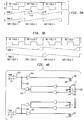
- Signal A illustrated in Figure 3A is the vertical synchronizing signal that is generated by a reference source or reproduced from the information on the tape. Basically, each pulse in the signal indicates the beginning of a new field of video information.
- Signal B in Figure 3A relates to the operation of the scanning drum tachometer. This signal is a square wave signal which is at a logic high value for one-half of the revolution of the scanning drum 10 and at a logic low value for the second half of the revolution.
- Figure 3A illustrates the need for 1-1/2 revolutions of the scanning drum to reproduce each field of the video signal.
- Signals C and D respectively relate to the channel 1 and channel 2 heads.
- a solid line indicates the time during which the head is in contact with the tape
- a dashed line relates to the time that the head is out of contact with the tape.
- the on-tape and off-tape status of the heads corresponds to the respective high and low values of the scanning drum tachometer signal.
- signals C and D shown in Figure 3A illustrate the changing elevation of each of the heads during operation.
- the specific example illustrated in Figure 3A relates to a still frame mode in which the tape is stopped. In this mode of operation, the heads are reset after each field is reproduced, to enable the same field to be continuously displayed.
- the individual portions of the tape vertical synchronizing signal A are labelled "Field 1", “Field 2", "Field 3" to indicate the time sequence of the fields. In fact, however, during the freeze frame mode, they all pertain to the same field of the video signal, as shown by the labels below signal D.
- each head is varied as respectively shown by the sloped signals C and D, to maintain the heads at the proper position to scan the tracks of information.
- the heads for channel 1 are in contact with the tape and read the information therefrom.
- the heads for channel 2 are not in contact with the tape, their elevation is varied commensurate with that of the channel 1 heads.
- the elevation of the channel 1 heads continues to be varied in the same manner as those of channel 2, so that these heads will be properly positioned when they are brought back into contact with the tape.
- Figure 3A illustrates that the heads for channel 1 are playing back the video information and the heads for channel 2 are off tape.
- the elevation of the channel 2 heads are examined to see if a track jump, i.e. an elevation reset, is required. In the example shown in Figure 3A, such a reset is to be carried out. Accordingly, during this time the elevation of the channel 2 heads is reset so that they are in the proper position to reproduce the same field once they come into contact with the tape, i.e. during the first segment of the second field.
- the channel 2 heads are off tape for one-half of the revolution of the scanning drum, it can be appreciated that the elevation resetting operation can be carried out in a somewhat leisurely fashion, as indicated by the sloped line 40 for signal D.
- the repositioning of the heads does not have to be almost instantaneous, and thus the inherent inertia associated with the head positioning system can be readily accommodated.
- the heads for channel 1 are repositioned, as shown by the line 42. Once they are reset, their elevation is varied commensurate with that of the channel 2 heads, as indicated by the sloped line 44. Thus, once the channel 1 heads come into contact with the tape they are in the appropriate position to immediately begin reproducing the second segment of information for field 2. At the end of this segment, the channel 1 heads are again reset, as indicated by the line 46, in preparation to replay the same field when they once again come on tape. Thus, during the second field, the channel 1 heads are reset two times, with both resets occurring while the heads are off tape. During this same field, the channel 2 heads are not reset at all. Preferably, since neither of the heads are reset during the second segment of each frame, their respective positions are compared with one another at this time and the position of the off-tape head is matched to that of the on-tape head.
- FIG. 3B Another illustration of the relationship of the heads during a non-standard play mode is illustrated in Figure 3B.
- This particular example relates to the situation in which the tape is played at 1 1/2 times the normal play speed. In this mode, every third field of the video signal is skipped.
- the heads of the two channels alternately reproduce the video signal in the normal fashion, and their elevational positions are coordinated with one another. Since the first and second recorded fields are played back in succession, no track jump (head reset) occurs between these two fields. However, since the third field is to be skipped, a track jump occurs after the second field in a direction opposite the direction of the jump shown in Figure 3A, where a field is repeated.
- the channel 1 heads are off tape, and their elevation is reset by a distance equal to one track jump.
- they will begin reproducing the first segment of the fourth frame.
- the heads of the other channel are reset and then moved in accordance with channel 1 heads, so that they will be in the proper position to reproduce the second segment of the fourth field.
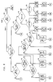
- a head position servo system for controlling the elevation of the heads in accordance with the foregoing procedure is illustrated in block diagram form in Figures 4A and 4B.
- the elevation of the heads of each channel is controlled in accordance with a voltage signal produced at a respective summing junction 20, 20′.
- the primary signal provided to the summing junction is a ramp voltage produced by a ramp generator 22.
- the ramp generator comprises an up/down counter 24 whose contents are provided to a D/A converter 26.
- the ramp generator 22 primarily functions to provide a signal related to the ratio of actual tape speed to normal playback speed.
- a capstan tachometer signal indicative of actual tape speed
- a steering logic circuit 28 receives a reference signal related to the normal play speed of the capstan tachometer.
- each pulse of the reference signal causes the up/down counter 24 to be incremented, and each pulse of the capstan tachometer causes it to be decremented.
- the number of pulses in the two signals will be equal and the contents of the up/down counter 24 will remain fixed, resulting in a ramp voltage having a zero slope.
- Another input to the summing junction 20 comprises the output signal from a dither generator 30.
- the dither generator produces a low amplitude signal having a frequency approximately twenty times the vertical synchronizing frequency of the television signal.
- the result of this dither signal is to produce a slight oscillation of the heads about the position determined by the ramp voltage. In accordance with well known principles, this oscillation induces an envelope in the RF signal that is reproduced by the heads.
- This RF signal is fed to an envelope detector 32 to produce a signal indicative of the shape of the envelope.
- the signal passes through a synchronous detector 33 to detect the dither signal present on the envelope.
- the output signal from the synchronous detector is supplied to a threshold detector, or slicer circuit, 34 which determines an offset or centering error for the head. If an error is present, as indicated by a non-symmetry in the RF envelope, the threshold detector provides an add or subtract input signal to the steering logic in dependence upon the direction of the offset.
- These input signals cause a pulse from a clock 35 to be sent to the up or down input terminal of the counter 24, to thereby "bump" the ramp signal in the appropriate direction to center the head on the track.
- only one or two pulses of this type might be applied for each field of the video signal, to provide a slow rate correction.
- the output signal from the envelope detector 32 is also applied to a track curvature filter 36.
- This filter integrates the output signal of the envelope detector over several tracks of the tape, to provide an output signal indicative of the general shape of a number of tracks.
- This signal is provided as a third input signal to the summing junction 20, and compensates for long-term effects such as stretching of the tape.
- the elevation control signals from the summing junctions 20 and 20′ are applied to one input terminal of respective operational amplifiers 100,101.
- the output signal from each amplifier is summed with a position signal on a line 102,103 amplified in an amplifier 104,105, and applied to a voice coil 106,107.
- the voice coils 106,107 comprise respective actuators which operate in a magnetic field for controlling the elevational position of the magnetic transducing heads (not shown in Figure 4B).
- each head is sensed and fed back as the position signal which appears on the lines 102,103.
- This position signal can be provided by means of an optical sensor.
- the arm or other support upon which the magnetic heads are mounted can include a blade 108 or other suitable light blocking device, which is disposed between an LED 110 and a pair of photodiodes 112,114.
- the blade 108 equally shades each of the photodiodes 112,114.
- the signal from each photodiode is provided to a differential amplifier 116. Since they are equally shaded, they will produce equal output signals, and thus the position signal provided on line 102 will be at a null value.
- the blade 108 When the heads are moved from their normal position, the blade 108 will allow more of the light from the LED 110 to shine on one photosensor than the other. Thus, the differential amplifier 116 will become unbalanced, and provide an appropriate position signal 102 to be summed with the output signal from the operational amplifier 100. This summing results in an error signal that is applied by the amplifier 104 to the voice coil 106. In other words, if the heads are at the desired position indicated by the signal from the summing junction 20, the position signal 102 will be equal to the output signal from the operational amplifier 100 but of opposite polarity, so they cancel one another, and a very small error signal will be applied to the voice coil 106.
- the positioning system for the channel 2 heads operates in a similar fashion.
- the steering logic 28 ( Figure 4A) also receives track jump, or reset, signals for repositioning the head upon completion of the reproduction of a video field. More particularly, as the speed of the tape deviates from normal play speed, the output signal from the ramp generator 22 is a voltage signal having a positive or negative slope, depending upon whether the speed of the tape is greater than or less than normal play speed. The greater the deviation between normal and actual speeds, the greater the slope of the ramp voltage signal. As a result, the elevation of the head continues to be displaced farther from its normal play position, and it must be periodically reset at the completion of the scan of a video field to properly position it for the scanning of the next subsequent field, in accordance with well known principles.
- the head must be repositioned a distance related to one field on the tape after each field is reproduced.
- the head would be repositioned a distance related to the width of one track.
- the head In recording systems which use a segmented format, however, the head must be repositioned by a distance related to the width of a multiple number of tracks. This multiple is determined by the number of segments per field as well as the number of heads which simultaneously scan the tape during each segment. In the presently illustrated example, a one field displacement of the head would be related to the width of six successive tracks.
- the precise amount of the jump is not exactly equal to six track widths, but is slightly less than or greater than this distance as determined by actual tape speed.
- the elevation resets must also be coordinated with the on-tape and off-tape status of the heads, and the particular segment of information, i.e. whether it pertains to the beginning or end of a field.
- This information is fed to a track jump logic circuit 50.
- the channel information could merely comprise the binary scanner tachometer signal, which indicates whether the scanning drum is in the first or second half of its revolution, and thus whether the channel 1 or channel 2 heads are on tape.
- the segment signal is obtained from the tape itself.
- each track of information recorded on the tape can contain a preamble or otherwise be encoded to identify the particular segment of the field to which it relates. This enables the first and last segments to be readily identified.
- the particular segment that is being reproduced can be determined by the tape vertical synchronizing signal and the scanner tachometer signal, or by means of information on a control track also recorded on the tape.
- the track jump logic circuit 50 produces an output signal to the steering logic 28 to indicate when an elevational reset is to occur. In particular, this information indicates the magnitude of the reset and the direction in which it is to take place.
- the signal from the track jump logic circuit 50 is applied to the steering logic 28 through a set of timer chips 52.
- the track jump logic loads one of these chips with the number of ramp bits to jump, and the other chip is loaded with the rate at which the jump is to occur.
- the steering logic feeds an appropriate number of pulses to the up or down counting input of the counter 24, in accordance with the magnitude and direction of the reset that is to occur.
- the track jump logic circuit 50 is most preferably implemented in a suitably programmed microprocessor. More particularly, a number of the operations that are carried out in video tape recording machines are controlled by a central microprocessor.
- a microprocessor-controlled video tape recording and reproducing machine is disclosed, for example, in U.S. Patent No. 4,536,806.
- a microprocessor of the type disclosed in that patent can also be used to provide track jump information to the steering logic circuit 28.
- a flow chart of a subroutine for controlling a microprocessor to perform the track jump operation is illustrated in Figure 5.
- This subroutine might be entered by means of an interrupt to the microprocessor that is generated each time the scanning drum tachometer signal B changes state, for example, to indicate that one pair of heads has just gone off tape.
- the subroutine begins with a determination at step 60 of the heads which are presently on the tape. Such a determination can be made, for example, with reference to the scanner tachometer signal B shown in Figure 3A. Once this determination has been made, the program then checks at step 62 whether the particular segment that is being reproduced relates to the beginning of a field. If not, the program checks at step 64 whether the segment pertains to the end of a field.
- the program determines at step 66 whether the elevation of the heads is above a first predetermined upper limit. Such a determination can be made, for example, with reference to the ramp value generated by the up/down counter 24. If the heads are positioned above this limit, the program instructs the channel 2 steering logic, at step 68, to carry out a frame jump in a downward direction.
- this instruction can be the data loaded into the timer chips 52.
- each field comprises 6 tracks on the tape.
- a frame jump which encompasses two fields, would cause the heads to be moved downwardly a distance related to the width of 12 tracks on the tape, plus or minus a correction factor related to tape speed.
- Flag A is set to a value of 1 to indicate that a jump has occurred.
- Flag B is set to a value of 0 or 1 in dependence upon the direction of the jump. For example, a downward jump might be indicated by setting the flag B to a value of 0.
- the flag C is set to a 0 or a 1 in dependence upon whether a field (6 track) or frame (12 track) jump has been carried out. In the present case, the flag C could be set to a value of 1 to indicate a frame jump.
- step 70 determines whether the heads are located above a second upper limit which is lower than the first upper limit. If the heads are located above this second limit, the program proceeds to step 72 and instructs the steering logic for channel 2 to perform a field jump in the downward direction. Again, the flags A, B and C are set, except that the value for flag C differs from the value to which it is set in step 68.
- step 70 if the program determines that the head elevation is not above the second upper limit, it then proceeds to step 74 to determine whether the heads are located below a first lower limit. If so, the steering logic is instructed at step 76 to do a frame jump in the upward direction. Again, the flags A, B and C are set as appropriate. If the heads are not below the first lower limit, a determination is made in step 78 whether they are below a second lower limit which is above the height of the first lower limit. If so, the steering logic is instructed at step 80 to do a field jump in the upward direction, and the flags A, B and C are appropriately set. If the heads are not below the second lower limit, i.e. they are situated between the second upper limit and the second lower limit, no jump is required and the routine ends.
- step 82 determines whether the heads for the other channel were previously reset. This determination is made by checking the status of the flag A. If no jump was previously carried out, the routine ends. If, however, a jump has occurred, the program examines flag B in step 84 to determine the direction of the jump. In response thereto, the program proceeds to step 86 or 88, as appropriate, to examine flag C and determine whether a field or frame jump was carried out. In response to the status of this flag, the steering logic 28 for the channel 1 heads are instructed to carry out the appropriate jump in one of the steps 90, 92, 94 or 96. Then, the flags for channel 2 are cleared and the routine ends.
- the present invention provides an approach for the automatic positioning of video heads which are used to reproduce information that is recorded in a segmented format.
- the elevational position of the off-tape head in accordance with that of the on-tape head, the need for quick resetting of the heads at the beginning and end of each segment is avoided.
- resetting operations that are required by non-standard playback modes are coordinated with the on-tape and off-tape status of the heads to enable such resetting to be carried out at a reasonable rate that does not unduly stress the mechanical system which effects the head movement.
Landscapes
- Adjustment Of The Magnetic Head Position Track Following On Tapes (AREA)
- Television Signal Processing For Recording (AREA)
Claims (6)
- Appareil pour la lecture, sur une bande enregistrée, d'un signal vidéo composé d'une succession de trames, chacune enregistrée sur la bande dans plusieurs segments, chaque segment étant situé sur l'une distincte de multiples pistes dont chacune s'étend obliquement par rapport à la bande, l'appareil comprenant au moins deux transducteurs (A1, A2) qui sont disposés pour aller alternativement en, et hors de, contact avec la bande, l'élévation de chaque transducteur étant réglable dans un sens correspondant à une direction globalement transversale aux pistes, et un moyen (22, 24) pour appliquer à chaque transducteur un signal de déviation en rampe qui produit, pendant le balayage d'une piste dans un mode de lecture dans lequel la vitesse longitudinale de bande est différente de la vitesse longitudinale de bande pendant l'enregistrement, un déplacement progressif du transducteur correspondant, dans ladite direction, pour permettre au transducteur de demeurer adjacent à la piste respective, et un déplacement correspondant du transducteur qui n'est pas en contact avec la bande, pour positionner ce transducteur correctement pour le commencement du balayage d'une piste ;caractérisé par:un moyen de commande (50, 28, 28a) (a) pour détecter si un premier transducteur est en train de lire le dernier segment d'une trame et si l'autre transducteur est en train de lire le premier segment de la trame qui suit, (b) pour, pendant la lecture dudit dernier segment par ledit premier transducteur, faire effectuer, si nécessaire, à l'autre transducteur un déplacement de saut de piste, pour permettre audit autre transducteur de commencer correctement le balayage du premier segment de la trame qui suit, et (c) pour, pendant la lecture dudit premier segment de la trame qui suit par ledit autre transducteur, faire effectuer audit premier transducteur un déplacement de saut de piste correspondant.
- Appareil selon la revendication 1, dans lequel la bande est guidée suivant un trajet hélicoïdal autour d'un support de déplacement qui comprend un tambour rotatif (10) ; et dans lequel lesdits transducteurs (A1, A2) sont placés dans des positions qui sont espacées sensiblement de 180° suivant la circonférence dudit tambour.
- Appareil selon la revendication 1 ou 2, dans lequel chaque transducteur est l'une d'une paire respective de têtes de lecture adjacentes (A1, B1 ; A2, B2) disposées suivant une relation azimutale croisée.
- Appareil selon l'une quelconque des revendications précédentes, dans lequel le moyen de commande (50, 28, 28a) détermine si un déplacement de saut de piste est nécessaire pour un transducteur et le sens et l'amplitude d'un tel déplacement de saut de piste, et délivre des signaux d'indication correspondants pour commander le saut de piste de l'autre transducteur.
- Appareil selon l'une quelconque des revendications précédentes, dans lequel le moyen (22, 24) pour appliquer le signal en rampe est conçu pour produire le signal en rampe en fonction du rapport de la vitesse longitudinale réelle de la bande et d'une vitesse de lecture normale.
- Appareil selon l'une quelconque des revendications précédentes, dans lequel chaque trame est divisée en trois ou quatre segments, et dans lequel le signal lu est composé de segments lus alternativement par lesdits deux transducteurs.
Applications Claiming Priority (2)
| Application Number | Priority Date | Filing Date | Title |
|---|---|---|---|
| US07/265,189 US4933784A (en) | 1988-10-31 | 1988-10-31 | Automatic head position tracking system for video signals recorded in a segmented format |
| US265189 | 1988-10-31 |
Publications (3)
| Publication Number | Publication Date |
|---|---|
| EP0367440A2 EP0367440A2 (fr) | 1990-05-09 |
| EP0367440A3 EP0367440A3 (fr) | 1991-05-29 |
| EP0367440B1 true EP0367440B1 (fr) | 1996-05-29 |
Family
ID=23009389
Family Applications (1)
| Application Number | Title | Priority Date | Filing Date |
|---|---|---|---|
| EP89310672A Expired - Lifetime EP0367440B1 (fr) | 1988-10-31 | 1989-10-17 | Système de suivi automatique de la position de la tête pour des signaux vidéo enregistrés dans un format segmenté |
Country Status (5)
| Country | Link |
|---|---|
| US (1) | US4933784A (fr) |
| EP (1) | EP0367440B1 (fr) |
| JP (1) | JPH0821169B2 (fr) |
| KR (1) | KR0159499B1 (fr) |
| DE (1) | DE68926565T2 (fr) |
Families Citing this family (19)
| Publication number | Priority date | Publication date | Assignee | Title |
|---|---|---|---|---|
| JP2606308B2 (ja) * | 1988-07-28 | 1997-04-30 | ソニー株式会社 | デジタルvtrのダイナミックトラッキング方法 |
| US5210663A (en) * | 1989-04-10 | 1993-05-11 | Matsushita Electric Industrial Co., Ltd. | Tracking control device and magnetic recording and reproducing apparatus using the device |
| JP2580341B2 (ja) * | 1989-09-29 | 1997-02-12 | 三菱電機株式会社 | 磁気記録再生装置 |
| US5239430A (en) * | 1989-09-29 | 1993-08-24 | Sony Corporation | Digital information signal reproducing apparatus for reproducing a digital audio signal at a reproducing speed different from the recording speed |
| US5448540A (en) * | 1990-09-21 | 1995-09-05 | Victor Company Of Japan, Ltd. | Device for detecting the position of a recording/reproducing element |
| US5384642A (en) * | 1991-02-02 | 1995-01-24 | Samsung Electronics Co., Ltd. | Tracking and picture quality in a VTR |
| KR930001645B1 (ko) * | 1991-02-13 | 1993-03-08 | 삼성전자주식회사 | 자동 트랙킹 방법 |
| WO1994011991A1 (fr) * | 1992-11-16 | 1994-05-26 | Ampex Systems Corporation | Format de bande magnetique permettant l'enregistrement de signaux audio-video et audio numeriques |
| US6246551B1 (en) * | 1998-10-20 | 2001-06-12 | Ecrix Corporation | Overscan helical scan head for non-tracking tape subsystems reading at up to 1X speed and methods for simulation of same |
| US6307701B1 (en) | 1998-10-20 | 2001-10-23 | Ecrix Corporation | Variable speed recording method and apparatus for a magnetic tape drive |
| US6381706B1 (en) | 1998-10-20 | 2002-04-30 | Ecrix Corporation | Fine granularity rewrite method and apparatus for data storage device |
| US6367047B1 (en) | 1998-10-20 | 2002-04-02 | Ecrix | Multi-level error detection and correction technique for data storage recording device |
| US6421805B1 (en) | 1998-11-16 | 2002-07-16 | Exabyte Corporation | Rogue packet detection and correction method for data storage device |
| US6367048B1 (en) | 1998-11-16 | 2002-04-02 | Mcauliffe Richard | Method and apparatus for logically rejecting previously recorded track residue from magnetic media |
| US6603618B1 (en) | 1998-11-16 | 2003-08-05 | Exabyte Corporation | Method and system for monitoring and adjusting tape position using control data packets |
| US6308298B1 (en) | 1998-11-16 | 2001-10-23 | Ecrix Corporation | Method of reacquiring clock synchronization on a non-tracking helical scan tape device |
| US6364234B1 (en) | 2000-03-10 | 2002-04-02 | Michael Donald Langiano | Tape loop/slack prevention method and apparatus for tape drive |
| US6624960B1 (en) | 2000-03-10 | 2003-09-23 | Exabyte Corporation | Current sensing drum/cleaning wheel positioning method and apparatus for magnetic storage system |
| US8873194B1 (en) * | 2014-04-01 | 2014-10-28 | Lsi Corporation | Touchdown detection in magnetic disk storage devices |
Citations (1)
| Publication number | Priority date | Publication date | Assignee | Title |
|---|---|---|---|---|
| EP0067562A1 (fr) * | 1981-06-09 | 1982-12-22 | Sony Corporation | Appareil de reproduction magnétique |
Family Cites Families (21)
| Publication number | Priority date | Publication date | Assignee | Title |
|---|---|---|---|---|
| JPS5650329B2 (fr) * | 1972-05-22 | 1981-11-28 | ||
| US4151570A (en) * | 1976-03-22 | 1979-04-24 | Ampex Corporation | Automatic scan tracking using a magnetic head supported by a piezoelectric bender element |
| JPS5492308A (en) * | 1977-12-29 | 1979-07-21 | Sony Corp | Head tracking device in recorder-reproducer |
| DE2751180C2 (de) * | 1977-11-16 | 1979-11-15 | Grundig E.M.V. Elektro-Mechanische Versuchsanstalt Max Grundig, 8510 Fuerth | Verfahren und Anordnung zur störungsfreien Standbildwiedergabe |
| JPS5497007A (en) * | 1978-01-17 | 1979-07-31 | Sony Corp | Head supporting structure |
| JPS6125071Y2 (fr) * | 1978-03-03 | 1986-07-28 | ||
| JPS54148421A (en) * | 1978-05-15 | 1979-11-20 | Sony Corp | Automatic tracking device for rotary magnetic head |
| JPS5538649A (en) * | 1978-09-07 | 1980-03-18 | Sony Corp | Tracking unit of magnetic head |
| JPS5539478A (en) * | 1978-09-14 | 1980-03-19 | Sony Corp | Regenerator of video signal |
| AU539426B2 (en) * | 1979-03-15 | 1984-09-27 | Sony Corporation | Automatic head height control apparatus |
| JPS5668922A (en) * | 1979-11-06 | 1981-06-09 | Sony Corp | Magnetic recording and reproducing device |
| JPS5683835A (en) * | 1979-12-07 | 1981-07-08 | Matsushita Electric Ind Co Ltd | Tracking device |
| DE3160763D1 (en) * | 1980-04-08 | 1983-09-22 | Minnesota Mining & Mfg | Automatic track following feature for helical video recorder |
| JPS56157182A (en) * | 1980-05-07 | 1981-12-04 | Victor Co Of Japan Ltd | Tracking system |
| JPS56159858A (en) * | 1980-05-10 | 1981-12-09 | Sony Corp | Tracking control unit in magnetic recording and reproducing device |
| DE3045543A1 (de) * | 1980-12-03 | 1982-07-01 | Robert Bosch Gmbh, 7000 Stuttgart | Verfahren und anordnung zur wiedergabe von auf einem aufzeichnungstraeger in einzelnen spuren aufgezeichneten videosignalen |
| DE3045541A1 (de) * | 1980-12-03 | 1982-07-01 | Robert Bosch Gmbh, 7000 Stuttgart | Verfahren und anordnung zur wiedergabe von auf einenaufzeichnungstraeger in einzelnen spuren aufgezeichneten videosignalen |
| GB2111288B (en) * | 1981-11-20 | 1985-04-11 | Sony Corp | Magnetic tape recording and reproducing arrangements |
| JPH0749524Y2 (ja) * | 1984-12-17 | 1995-11-13 | ナカミチ株式会社 | 移動体の移動制御装置 |
| JPH0695377B2 (ja) * | 1985-03-12 | 1994-11-24 | ソニー株式会社 | バイモルフヘツドのバイモルフ駆動装置 |
| JP2606308B2 (ja) * | 1988-07-28 | 1997-04-30 | ソニー株式会社 | デジタルvtrのダイナミックトラッキング方法 |
-
1988
- 1988-10-31 US US07/265,189 patent/US4933784A/en not_active Expired - Lifetime
-
1989
- 1989-10-17 EP EP89310672A patent/EP0367440B1/fr not_active Expired - Lifetime
- 1989-10-17 DE DE68926565T patent/DE68926565T2/de not_active Expired - Fee Related
- 1989-10-30 KR KR1019890015705A patent/KR0159499B1/ko not_active IP Right Cessation
- 1989-10-31 JP JP1284635A patent/JPH0821169B2/ja not_active Expired - Lifetime
Patent Citations (1)
| Publication number | Priority date | Publication date | Assignee | Title |
|---|---|---|---|---|
| EP0067562A1 (fr) * | 1981-06-09 | 1982-12-22 | Sony Corporation | Appareil de reproduction magnétique |
Also Published As
| Publication number | Publication date |
|---|---|
| JPH02172013A (ja) | 1990-07-03 |
| EP0367440A2 (fr) | 1990-05-09 |
| JPH0821169B2 (ja) | 1996-03-04 |
| EP0367440A3 (fr) | 1991-05-29 |
| KR900006914A (ko) | 1990-05-09 |
| DE68926565T2 (de) | 1997-01-23 |
| KR0159499B1 (ko) | 1999-01-15 |
| DE68926565D1 (de) | 1996-07-04 |
| US4933784A (en) | 1990-06-12 |
Similar Documents
| Publication | Publication Date | Title |
|---|---|---|
| EP0367440B1 (fr) | Système de suivi automatique de la position de la tête pour des signaux vidéo enregistrés dans un format segmenté | |
| EP0368497B1 (fr) | Contrôle d'asservissement dynamique de la position d'une tête pour un système de lecture à bande magnétique | |
| EP0004476B1 (fr) | Correcteur d'erreurs de la base de temps pour un appareil de lecture de disque optique | |
| US4044388A (en) | Interactive servo control system for use with a rotating-head magnetic tape player | |
| JPH02107079A (ja) | 磁気記録再生装置 | |
| NL8100740A (nl) | Apparaat voor weergave van op een registratiemedium opgenomen informatiesignalen. | |
| KR870001119B1 (ko) | 비데오 디스크 및 비데오 디스크 플레이어에서 편심률을 측정하는 방법 | |
| CA1235221A (fr) | Enregistrement video numerique | |
| US4120008A (en) | Overlap track servo for dynamic position correction in a rotary-head tape recorder | |
| EP0103463B1 (fr) | Appareil et méthode de positionnement d'enregistrements ultérieurs sur une bande vidéo par rapport à un enregistrement existant | |
| US4268876A (en) | Magnetic reproducing device | |
| US4426665A (en) | Automatic track following feature for helical video recorder | |
| CA1193005A (fr) | Systeme de centrage automatique pour magnetoscope a balayage helicoidal | |
| EP0364986B1 (fr) | Appareil de réproduction de signaux vidéo et audio | |
| US4432026A (en) | Apparatus and method for determining read head position | |
| EP0119201A1 (fr) | Asservissement ameliore de suivi automatique de la position de la tete pour un dispositif d'enregistrement et de reproduction sur bande magnetique a tete rotative. | |
| JPS62234222A (ja) | 予め記録された基準トラツクを使用する情報信号記録及び/または再生方式並びに方法 | |
| US4734799A (en) | Apparatus for tracking magnetic head on rotary magnetic recording medium by envelope detection | |
| AU640183B2 (en) | System for controlling positions of record tracks relative to a scanning trace of a head device | |
| EP0119199B1 (fr) | Procede et dispositif de production d'un signal artificiel de synchronisation verticale pour l'enregistrement video sur bande magnetique | |
| EP0240288A2 (fr) | Appareil et méthode de mesure d'avancement de bande pour un appareil d'enregistrement/reproduction de signaux vidéo à têtes rotatives | |
| KR880000396B1 (ko) | 트래킹 제어방식 | |
| JP2674205B2 (ja) | 映像信号再生装置 | |
| JPS6177187A (ja) | ウエブ位置制御装置 | |
| JPH02281453A (ja) | 磁気記録再生装置 |
Legal Events
| Date | Code | Title | Description |
|---|---|---|---|
| PUAI | Public reference made under article 153(3) epc to a published international application that has entered the european phase |
Free format text: ORIGINAL CODE: 0009012 |
|
| AK | Designated contracting states |
Kind code of ref document: A2 Designated state(s): AT DE FR GB NL |
|
| PUAL | Search report despatched |
Free format text: ORIGINAL CODE: 0009013 |
|
| AK | Designated contracting states |
Kind code of ref document: A3 Designated state(s): AT DE FR GB NL |
|
| 17P | Request for examination filed |
Effective date: 19910824 |
|
| 17Q | First examination report despatched |
Effective date: 19930407 |
|
| RAP1 | Party data changed (applicant data changed or rights of an application transferred) |
Owner name: AMPEX SYSTEMS CORPORATION |
|
| GRAH | Despatch of communication of intention to grant a patent |
Free format text: ORIGINAL CODE: EPIDOS IGRA |
|
| GRAA | (expected) grant |
Free format text: ORIGINAL CODE: 0009210 |
|
| RBV | Designated contracting states (corrected) |
Designated state(s): DE GB |
|
| AK | Designated contracting states |
Kind code of ref document: B1 Designated state(s): DE GB |
|
| REF | Corresponds to: |
Ref document number: 68926565 Country of ref document: DE Date of ref document: 19960704 |
|
| PLBE | No opposition filed within time limit |
Free format text: ORIGINAL CODE: 0009261 |
|
| STAA | Information on the status of an ep patent application or granted ep patent |
Free format text: STATUS: NO OPPOSITION FILED WITHIN TIME LIMIT |
|
| 26N | No opposition filed | ||
| REG | Reference to a national code |
Ref country code: GB Ref legal event code: 732E |
|
| REG | Reference to a national code |
Ref country code: GB Ref legal event code: IF02 |
|
| PGFP | Annual fee paid to national office [announced via postgrant information from national office to epo] |
Ref country code: DE Payment date: 20061012 Year of fee payment: 18 |
|
| PG25 | Lapsed in a contracting state [announced via postgrant information from national office to epo] |
Ref country code: DE Free format text: LAPSE BECAUSE OF NON-PAYMENT OF DUE FEES Effective date: 20080501 |
|
| PGFP | Annual fee paid to national office [announced via postgrant information from national office to epo] |
Ref country code: GB Payment date: 20081015 Year of fee payment: 20 |
|
| REG | Reference to a national code |
Ref country code: GB Ref legal event code: PE20 Expiry date: 20091016 |
|
| PG25 | Lapsed in a contracting state [announced via postgrant information from national office to epo] |
Ref country code: GB Free format text: LAPSE BECAUSE OF EXPIRATION OF PROTECTION Effective date: 20091016 |