EP0367290A2 - Méthode pour commander le déplacement d'un curseur et appareil pour sa mise en oeuvre - Google Patents
Méthode pour commander le déplacement d'un curseur et appareil pour sa mise en oeuvre Download PDFInfo
- Publication number
- EP0367290A2 EP0367290A2 EP89120405A EP89120405A EP0367290A2 EP 0367290 A2 EP0367290 A2 EP 0367290A2 EP 89120405 A EP89120405 A EP 89120405A EP 89120405 A EP89120405 A EP 89120405A EP 0367290 A2 EP0367290 A2 EP 0367290A2
- Authority
- EP
- European Patent Office
- Prior art keywords
- cursor
- positions
- keyboard
- registration
- move control
- Prior art date
- Legal status (The legal status is an assumption and is not a legal conclusion. Google has not performed a legal analysis and makes no representation as to the accuracy of the status listed.)
- Withdrawn
Links
Images


Classifications
-
- G—PHYSICS
- G06—COMPUTING OR CALCULATING; COUNTING
- G06F—ELECTRIC DIGITAL DATA PROCESSING
- G06F3/00—Input arrangements for transferring data to be processed into a form capable of being handled by the computer; Output arrangements for transferring data from processing unit to output unit, e.g. interface arrangements
- G06F3/01—Input arrangements or combined input and output arrangements for interaction between user and computer
- G06F3/048—Interaction techniques based on graphical user interfaces [GUI]
- G06F3/0487—Interaction techniques based on graphical user interfaces [GUI] using specific features provided by the input device, e.g. functions controlled by the rotation of a mouse with dual sensing arrangements, or of the nature of the input device, e.g. tap gestures based on pressure sensed by a digitiser
- G06F3/0489—Interaction techniques based on graphical user interfaces [GUI] using specific features provided by the input device, e.g. functions controlled by the rotation of a mouse with dual sensing arrangements, or of the nature of the input device, e.g. tap gestures based on pressure sensed by a digitiser using dedicated keyboard keys or combinations thereof
- G06F3/04892—Arrangements for controlling cursor position based on codes indicative of cursor displacements from one discrete location to another, e.g. using cursor control keys associated to different directions or using the tab key
Definitions
- the present invention generally relates to a method of controlling the move of a cursor on a screen of a display apparatus used in combination with a computer or the like and an apparatus for carrying out the method. More particularly, the present invention relates to a cursor move control method as well as a cursor move control apparatus for use in a document processing system, a drawing system or the like which can be implemented by making use of a computer.
- the means for moving a cursor on a display screen of a display apparatus has been generally and conventionally realized by the keys arrayed on a keyboard and labeled with arrows (known as arrow keys or cursor move keys).
- arrow keys or cursor move keys
- positioning of the cursor at the aimed position on the display screen through operation of the arrow keys requires unexpectedly a lot of time and more or less troublesome manipulation.
- the arrow key(s) must be successively operated or depressed many times in order to move the cursor to the destination.
- the cursor on the screen is moved on the display screen from the current position of the cursor to the aimed position or destination by following the shortest path between them in response to actuation of the arrow key(s) by the operator. Consequently, the abovementioned techniques also suffer from the inconvenience that the arrow key(s) has to be successively depressed many times in dependence on the distance intervening between the current cursor position and the destination to which the cursor is to be moved.
- An object of the present invention is to provide a cursor move control method and an apparatus for carrying out the same which can assure a facilitated operation for moving the cursor from one position to another within a relatively short time, thereby enhancing and improving the manipulatability of the document and/or graphics processing apparatus.
- At least one desired position on the screen of a display apparatus used in combination with a document and/or graphics processing apparatus is previously registered in registration means, wherein upon actuation of a predetermined key such as a TAB key or a BACK TAB key, positional difference between the current cursor position and the desired cursor destination (i.e. the position to which the cursor is to be moved) registered in the registration means is arithmetically determined, whereon the cursor is moved from the current position to the desired destination in accordance with or on the basis of the difference thus determined.
- a predetermined key such as a TAB key or a BACK TAB key
- pairs of first and second desired positions on the display screen are previously registered in a registration table.
- the cursor is moved to the second position which is paired with the first position. In this manner, the cursor having been moved to the first position is automatically moved to the second position in succession.
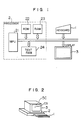
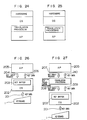
- Fig. 1 is a block diagram showing a general arrangement of a data processing apparatus which may be constituted by a relatively small size computer of such species as is generally called the personal computer and to which the present invention is applied
- Fig. 2 is a view showing, by way of example only, an outer appearance of the apparatus shown in Fig. 1.
- reference numeral 1 denotes a keyboard
- 2 denotes a processing unit or processor constituting the main part of the data processing apparatus
- numeral 3 denotes a display unit.
- the key board 1 there are arrayed a multiplicity of keys.
- the processing unit 2 which includes a microprocessor (MPU) 21, a read-only memory (ROM in abbreviation), a read/write memory (or random access memory hereinafter also referred to as RAM) 23 and a read/write memory for storing text information corresponding to the display to be generated on the screen of the display unit 3 (this memory will also be referred to as TEXT RAM) 24.
- the RAM is implemented in a structure corresponding to that of the display screen (SC) of the display unit 3 in such a manner that the characters written in the TEXT RAM 24 can be displayed at the positions corresponding to the addresses at which the characters are written.
- the microprocessor (MPU) 21 reads out a program from the ROM or the RAM for executing a predetermined processing in accordance with the program.
- the results of the processing is displayed on the display unit 3 which is also adapted to display the data inputted with the aid of the keyboard 1.
- the display unit 3 has the screen for display, as designated by SC.
- a cursor CS which serves to indicate those locations or positions on the screen at which the processing or operation is to be performed.
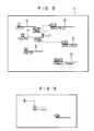
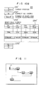
- Fig. 3 is a view for illustrating in the manner in which the cursor is moved according to the teaching of the present invention incarnated in the first embodiment.
- reference numeral 4 designates a text displayed on the display screen of the display unit 3 shown in Figs. 1 and 2.
- This text is assumed to be of a document having a predetermined format such as, for example, a booking slip which is prepared by the operator through operation of the keyboard 1 and stored in the TEXT RAM 24. It is further assumed that this text or document is to be repeatedly reused or issued. Accordingly, sentences of predetermined formulae which can be used in common to all the documents to be issued are inputted once and held constantly.
- the corresponding regions located above solid line segments designated by 5 to 10, respectively, in Fig. 3 are reserved in blank.
- the operator reads out the relevant text or document information from the TEXT RAM 24 to display it on the screen SC of the display unit 3 and inputs the desired character data in the blank regions one by one while viewing the document being displayed.
- Manipulation and move of the cursor according to the instant embodiment of the invention is such as follows.
- the depression of the TAB key makes it possible to input the desired character data sequentially in the individual blank regions in the increasing order of the numerals shown enclosed with the rectangles at the left ends of the blank regions, respectively.
- the character data can be inputted in the blank regions sequentially in the reversed order, i.e. in the decreasing order of the abovementioned numerals.
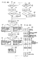
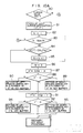
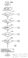
- Fig. 4A is a flow chart for illustrating a cursor move control method according to the instant embodiment of the invention
- Fig. 4B is a view showing various areas provided within the RAM 23 incorporated in the processing unit 2 (Fig. 1).
- reference numeral 231 designates an area for storing the coordinate values (X, Y) representing the current position of the cursor on an X-Y coordinate system
- numeral 232 designates an area for storing the current number (No.) of a variable N
- numeral 233 designates an area for storing the maximum value of the variable N, i.e. the number of registrations of the tab cursor
- reference numeral 235 designates a work area for the variables k and X′ and Y′ which will be explained in the course of the description which follows.
- step 30 shown in Fig. 4A it is decided whether or not the TAB key has been depresses or not.
- the variable N is incremented by "1" (one) at a step 31.
- the variable N incremented is compared with the value Max. N representing the number of the tab cursor registrations at a step 32.
- the value of the variable N incremented is greater than that of Max. N, the variable N is initialized to 1 at a step 32.
- value N is equal to or smaller than Max.
- the X-coordinate value X of the current cursor position is subtracted from the X-coordinate value X N of the start position corresponding to the value of N resulting from the incrementation, whereon the difference X′ resulting from the subtraction is stored in the work area 235.
- comparison is made between the values X′ and 0.
- X′ is greater than 0, i.e. when X′ is positive, then a right-heading arrow key is set in a number equal to the value of X′ in a key buffer for storing temporarily the character data for display at a step 36.
- X′ is smaller than 0, i.e.
- a left-heading arrow key is set in a number equal to the value of X′ in the key buffer at a step 37.
- the processing similar to the steps 34 to 37 mentioned above is performed for the Y-coordinate value. More specifically, the Y-coordinate value Y of the current cursor position is subtracted from the Y-coordinate value Y N of the start position corresponding to the value of the variable N incremented at the step 38, whereon the value of difference Y′ resulting from the above subtraction is stored in the work area 235 allocated to the value Y′.
- the value Y′ is compared with 0. When the value Y′ is greater than 0, i.e.
- a down-heading arrow key is set in a number equal to the value of Y′ in the key buffer.
- an up-heading arrow key is set in a number equal to the value of Y′ in the key buffer.
- the cursor is automatically moved on the display screen (SC) from the current position (X N , Y N ) displayed before operation of the TAB key to the start position (X N+1 , Y N+1 ) of the destination blank region.
- ordinary key input processing can be performed for the blank region into which the cursor has now been moved.
- step 42 when decision is made at the step 30 that the TAB key is not yet actuated, it is then decided at a step 42 whether or not the BACK TAB key has been depressed.
- the answer of the decision step 42 is negative (N)
- ordinary character data input operation can be performed.
- the content (N) of the current number (No.) storage area 232 is decremented by "1" at a step 43, being followed by a step 54 at which the decremented value of the variable N is compared with "1".
- N is smaller than "1"
- the maximum value (Max Max.
- the processing steps 34 to 41 are executed with the content of the current number (No.) storage area 232 being held at (N - 1).
- the cursor is automatically moved from the current position (XN, YN) occupied by the cursor before actuation of the BACK TAB key to the start position (X N-1 , Y N-1 ) of the destination blank region on the display screen.
- FIG. 5 is a view for illustrating a cursor manipulating procedure for setting the tabs
- Fig. 6 is a flow chart for illustrating a tab setting method according to the instant embodiment of the invention.
- the cursor located at the home position is first moved to the position designated by the numeral 1 enclosed with the rectangle by operating correspondingly the keys labeled with the arrow marks.
- the tab setting is performed by depressing the associated key or keys to thereby set the tab at the position designated by the numeral 1 enclosed with the rectangle or tetragon.
- the keys for enabling the tab setting may be, for example, those marked "CTRL (or CONTROL)" and O. By touching these keys with fingers simultaneously, the tab setting can be accomplished.
- the arrow-marked keys are operated again to thereby move the cursor from the position designated by the numeral 1 enclosed with the tetragon to the position designated by the numeral 2 also enclosed with a tetragon, whereon the tab setting input keys are pressed simultaneously to thereby set the tab at the position designated by the tetragon-enclosed numeral 2.
- a key labeled "CTRL” (abbreviation of CONTROL) and an alphabetic key “T", by way of example, are simultaneously pressed down at a step 50 to initialize a variable k to "1".
- the cursor is moved to a desired position (X, Y) by means of the arrow-marked keys, whereon the X- and Y-coordinate values are registered in a registration table 234 at an area (X1, Y1) by actuating the tab setting input keys at a step 52.
- the input operation for the tab setting can be achieved by touching simultaneously the keys labeled, for example, "CTRL" and O.
- a corresponding message is issued to the processing unit 2 (Fig. 1) by actuating, for example, a key labeled "ESC” (an abbreviation of "ESCAPE"). So long as the ESC key remains not actuated, the variable k is incremented by "1" at a step 55, and the step 51 is then regained to register another desired position.
- the ESC key is pressed. Subsequently, the current value of the variable k is stored in the Max. N area 233 at a step 56. Next, at a step 57, the value of N stored in the current number (No.) registration area 232 is initialized to "0". Then, the procedure for registering the desired tab positions comes to an end.
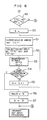
- Fig. 7 is a block diagram showing a structure of the cursor move control apparatus according to a second exemplary embodiment of the present invention.
- the display unit 3 connected to the keyboard 1 is provided with a cursor controller 300, a key buffer 301 and a display device 302.
- the controller 300 stores sequentially in the key buffer 301 the character strings inputted through the keyboard 1.
- the display device 302 displays the character data read out from the key buffer 301 sequentially.
- a start position registration controller 60 executes the processing steps 50 to 57 described above to thereby store the requisite information in the RAM 23 at the areas 231 to 235.
- the current number (No.) storage area controller 61 serves to increment and decrement the variable N at the steps 31 and 43 as well as for the setting of N at the steps 33 and 45, as described hereinbefore.
- a comparator 62 serves for comparison between the variable N and the maximum value Max. N thereof and comparison of the variable N with "1".
- An arithmetic unit 63 performs the calculation of X N - X at the step 34, while the other arithmetic unit 64 performs the calculation of Y N - Y at the step 38.
- a key buffer controller 65 receives the output from the arithmetic unit 63 for executing the processing steps 35 to 37.
- the key buffer controller 65 causes the cursor controller 300 to load the key buffer 301 with the right-heading arrow key data or the left-heading arrow key data representing the number corresponding to the result of the arithmetic operation performed by the arithmetic unit 63.
- the key buffer controller 66 receives the output from the arithmetic unit 64 to execute the processing steps 39 to 41. More specifically, the key buffer controller 66 causes the cursor controller 300 to store in the key buffer 301 the down-heading arrow key data or the up-heading arrow key data representing the number corresponding to the result of the arithmetic operation performed by the arithmetic unit 64.
- the key buffer controllers are provided in a pair. However, it goes without saying that only one key buffer controller may be provided. In that case, the data processing is performed serially in the X- and Y-axial directions, respectively.
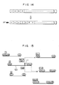
- Fig. 8 is a diagram for illustrating in the manner in which the key data are stored in the key buffer 301. Referring to Fig. 8, description will be made of operation of the first and second embodiments in particular with regard to the key buffer. It is assumed that a key input request is issued from an application program running on a data processing apparatus which is operated as the document processing apparatus according to the invention. In that case, when the input key is the TAB key or BACK TAB key, the key data arithmetically determined through the procedure described above (the arrow key data in numbers corresponding to the values X′ and Y′, respectively) are once stored in the key buffer and subsequently transferred sequentially to the application program, whereby the automatic move of the cursor is realized.
- the mark indicating the start position is not displayed. It should however be understood that a more human-friendly document processing apparatus can be implemented by displaying the start position mark.
- This mark may be allocated with a space corresponding to one character. However, with a view to ensuring the comfortable character input operation, the mark may also be displayed by using an area corresponding only to a part of one character space.
- Fig. 9 is a schematic diagram for illustrating the moves of the cursor according to the teaching of the invention incarnated in the third embodiment.
- Reference numeral 4′ designates a text generated on the screen of the display 3 shown in Figs. 1 and 2. This text is similar to that described hereinbefore in conjunction with the first embodiment. Thus, upon generation of the text, those regions located above the line segments 70 to 74 are left blank. According to the instant embodiment, the move of the cursor is performed in such a manner that the cursor moved to a specific position is automatically moved to another specific position which is paired with the former. More specifically, let's suppose that the cursor 11 located at the position in the blank region overlying the line segment 72 shown in Fig.
- the cursor arrives at the end (rightmost) position given by the coordinates (IX N+1 , IY N+1 ) of the blank region lying above the line segment 73. Then, the cursor is automatically moved again to the start position D(N + 1) given by the coordinates (DX N+1 , DY N+1 of the blank region overlying the line segment 74, which start position D(N + 1) is paired with the end position I(N + 1) mentioned above.
- the cursor is automatically moved sequentially from the position I(1) to the position D(1), I(2) to D(N), I(N) to D(N), I(N + 1) to D(N + 1), and then I(Max. N) to D(Max. N).
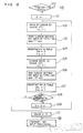
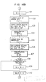
- Fig. 10A shows a flow chart for illustrating the cursor move control method according to the third embodiment of the invention
- Fig. 10B is a schematic diagram showing individual areas of the RAM 23 incorporated in the processing unit 2 (Fig. 1) to be used for carrying out the cursor move control method.
- reference numeral 231′ designates an area for storing the value of the current cursor position (X, Y) on an X-Y coordinate system
- numeral 232′ denotes a work area for storing the current number (No.) of a variable M
- numeral 233′ denotes an area for storing the maximum value of the variable M, i.e.
- numeral 234′ designates an end/start position registration table area in which the coordinate values of the end positions of the individual blank regions and those of the start positions of the destination blank regions to which the cursor arrived at the end positions are to be subsequently moved are registered in pairs, respectively, and reference numeral 235′ designates a work area for the coordinate values X′ and Y′ and the variable k , the roles of which will be made apparent in the course of the following description.
- a step 80 decision is made to whether or not a cursor move key is actuated.
- the answer of this decision step is negative (N)
- the ordinary typewriting operation can be performed in continuation.
- the decision step 80 results in the affirmative answer (Y)
- the destination position (X′, Y′) to which the cursor is to be moved is detected at a step 81, being then followed by a step 82 where the variable k is initialized to "1".
- the variable k is compared with the maximum value M of the registered number of the end/start positions.
- the processing proceeds to a step 84 where it is checked whether or not the position coordinates (X′, Y′) are equal to the coordinates (IX1, IY1) registered in the registration table 234′. Unless the equality is found, the variable k is incremented by "1" at a step 85, whereon the step 82 is regained. In this manner, through the steps 82 to 85, it is checked whether or not the destination (X′, Y′) of the cursor coincides with any one of the end positions registered in the registration table 234′.
- the variable k is stored in the current number (No.) storage area 232′ at a step 86, whereon a step 87 is executed.
- the X-coordinate value X of the end position for which the coincidence is detected is subtracted from the X-coordinate DX M of the start position which is set in a pair with the abovementioned end position.
- the result of the subtraction i.e. DX M - X is then stored in the area assigned to the coordinates X′ in the work area 235′ at a step 87.
- the value X′ stored in the work area 235′ is then compared with 0 (zero) at a step 88. If X′ is greater than 0, this means that the start position is located on the right hand side of the end position. Accordingly, the right-heading arrow key data is placed in the key buffer in a number equal to the value of X′. On the other hand, when the value of X′ is smaller than 0, this means that the start position lies on the left hand side of the end position. Accordingly, the left-heading arrow key data is placed in the key buffer in a number equal to the value of X′ at a step 90.
- the Y-coordinate value Y of the end position for which the coincidence is detected at the step 84 is subtracted from the Y-coordinate DY M of the start position paired with the abovementioned position at a step 91, the result of the subtraction (DY M - Y) being then stored in the area assigned to Y′ of the work area 235′.
- the value of Y′ stored in the work area 235′ is compared with 0 (zero). When Y′ is greater than 0, this means that the start position is located on the lower side of the end position. Accordingly, the down-heading arrow key data is placed in the key buffer in a number equal to the value of Y′.
- the up-heading arrow key is set in the key buffer in a number equal to the value of Y′.
- Fig. 11 is a schematic diagram for illustrating the cursor manipulation involved in setting the end/start cursor positions
- Fig. 12 is a flow chart for illustrating a method of setting the end/start cursor positions.
- Fig. 11 it is assumed that the end positions and the start positions are to be set up sequentially at locations I(1) and D(1), I(2) and D(2), and so forth, respectively.
- the cursor located at the home position is moved to the position I(1) by operating first a corresponding cursor move key.
- an input key commanding the setting of the end cursor position is depressed to thereby register the position I(1) in the end/start cursor position registration table 234′.
- the command for setting the end cursor position may be inputted by pressing, for example, the CTRL key and the I key, simultaneously.
- the cursor is moved from the position I(1) to the position D(1) by operating a corresponding cursor move key, whereon the input keys for commanding the setting of the start cursor position are operated to thereby register the position D(1) in the registration table 234′.
- the command for setting the start cursor position can be validated by depressing simultaneously the CTRL key and the O key, by way of example. In this way, the individual end and start positions are registered successively one by one.
- step 100 it is first decided at a step 100 whether or not the end/start cursor position setting mode has been validated in response to simultaneous actuation of the keys labeled, for example, "CTRL" and "S".
- the answer of the decision step 100 is negative (N)
- the ordinary typewriting operation can be performed in succession.
- the variable k is initialized to "1" (one) at a step 101.
- the cursor is moved to a desired end position with the aid of a corresponding arrow key.
- the desired end position (X, Y) is registered in the registration table 234′ at an area (IX k ,IY k ) at a step 104. Subsequently, the cursor is moved from the desired end position mentioned above to the start position of a desired destination blank region by operating a corresponding arrow key at a step 105. Thereafter, the CTRL key and the O key, by way of example, are depressed simultaneously to thereby register the start position (X, Y) in the registration table at a location (DX k , DY k ) at a step 105.
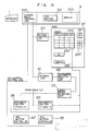
- Fig. 13 is a block diagram showing an arrangement of the cursor move control apparatus according to the third embodiment of the present invention.
- the structure of the keyboard 1 and the display unit 3 is similar to that of the apparatus according to the second embodiment described hereinbefore in conjunction with Fig. 7.
- a setting controller 120 is provided for executing the processings at the steps 100 to 110.
- a decision unit 121 is provided for executing the processing of the step 80, i.e. for making decision as to the operation (depression) of the cursor move keys.
- a destination position arithmetic unit 122 performs the processing at the step 81.
- a coincidence detector 123 executes the processing corresponding to the steps 83 to 85 for checking whether or not the cursor position (X′, Y′) coincides with any one of the end cursor positions stored in the registration table 234′.
- An arithmetic unit 124 executes the processing corresponding to the step 87 while a key buffer controller 125 responds to the output of the arithmetic unit 124 to thereby execute the processing steps 88 to 90.
- the key buffer controller 125 causes the cursor move controller 300 to store in the key buffer 301 the number of the right-heading arrow key data or the left-heading arrow key data which corresponds to the result of the arithmetic operation performed by the arithmetic unit 124.
- the other arithmetic unit 126 executes the processing of the step 91, while the other key buffer controller 127 receives the output of the arithmetic unit 126 to execute the processings at the steps 92 to 94. More specifically, the key buffer controller 127 causes the cursor move controller 300 to store in the buffer 301 the number of the up-heading arrow key data or down-heading arrow key data, which number corresponds to the result of the arithmetic operation performed by the arithmetic unit 126.
- Fig. 14 is a diagram for illustrating in the manner in which the key data are stored in the key buffer. Referring to Fig. 14, description will be made of operation of the third and fourth embodiments in particular with regard to the key buffer. It is assumed that a key input request is issued from an application program running on the data processing apparatus which is operated as a document processing apparatus according to the invention. In that case, when the input key is a cursor move key, the next cursor position is obtained through the procedure described above.
- the differences X′ and Y′ between the coinciding end position and the start position paired therewith along the X-coordinate axis and the Y-coordinate axis, respectively, are arithmetically determined in the manner described hereinbefore, whereupon the key data required for moving the cursor from the end position to the start position mentioned above, i.e. the arrow-marked key data in the numbers corresponding to the differences X′ and Y′, respectively, are once stored in the key buffers before being sequentially transferred to the application program. In this way, the automatic move of the cursor can be realized.
- steps of arithmetically determining the differences X′ and Y′ and registering them in the registration table 234′ are additionally provided between the steps 107 and 108 shown in Fig. 12.
- steps 87 and 91 shown in Fig. 10A are replaced by those for reading out the values X′ and Y′, respectively, from the registration table 234′.
- the arithmetic units 124 and 126 shown in Fig. 13 will have to be replaced by reading means for reading out the values X′ and Y′ from the registration table 234′.
- FIG. 15 A fifth embodiment of the present invention will be described by referring to Fig. 15 and Figs. 16A to 16B.
- Fig. 15 is a schematic diagram illustrating the move of the cursor according to the fifth embodiment which substantially corresponds to a combination of the first and third embodiments of the invention described hereinbefore. It is now assumed that the cursor 11 is positioned in a blank region overlying a line segment 130 and having a start position n (corresponding to the start position n in the case of the first embodiment and the start position D(N) in the case of the third embodiment). At this time, upon actuation of the TAB key or BACK key, the cursor 11 is moved to the start position of the region (n + 1) or (n - 1) as in the case of the first embodiment. When the cursor 11 is moved to the position I(N + 1) without the aid of the TAB key or BACK TAB key, the cursor is then moved to the start position D(N + 1) as in the case of the third embodiment.
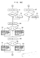
- Figs. 16A to 16E are flow chart for illustrating the cursor move control method according to the fifth embodiment of the present invention.
- a step 140 it is decided at a step 140 whether or not both the CTRL key and the S key are pressed down simultaneously. If the answer of this decision step 140 is affirmative (Y), the processing steps 101 to 110 shown in Fig. 16B are executed for thereby registering the start and end positions of the individual blank regions in the registration table. Since the processings at these step 101 to 110 have been described hereinbefore by reference to Fig. 12, repeated description will be unnecessary. On the other hand, when the decision step 140 results in the negative answer (N), the ordinary key input processing can be performed.
- step 141 decision is made as to whether or not both the CTRL and T keys are simultaneously depressed. If this decision step 141 results in the affirmative answer (Y), then the processing steps 50 to 57 shown in Fig. 16C are executed thereby to register the start positions of the individual blank regions in another registration table. Since these steps have also been described hereinbefore by reference to Fig. 6, repeated description will be unnecessary. On the other hand, if the answer of the decision step 141 is negative (N), the ordinary key input processing is performed. Next at a step 142, decision is made as to whether any cursor move key is touched. If the answer of this decision step 142 is affirmative (Y), the processing steps 81 to 94 shown in Fig.
- step 16D are executed, whereby the cursor, if it resides at any one of the end positions, is automatically moved to the start position paired with that end position.
- step 142 results in the negative answer (N)
- the ordinary key input processing is performed. Since these steps have also been described hereinbefore in conjunction with Figs. 10A and 10B, any further description will be unnecessary.
- step 143 it is decided whether or not the TAB key is pressed down. If the answer is affirmative (Y), the processing steps 31 to 41 shown in Fig. 16E are executed thereby to move the cursor to the start position (n + 1) shown in Fig. 15, by way of example.
- step 144 it is decided whether or not the BACK TAB key is depressed. If the answer is affirmative (N), the steps 43 to 45 and 34 to 41 shown in Fig. 16E are executed, as the result of which the cursor is moved to the start position, for example, (n - 1) shown in Fig. 15. On the other hand, when the answer of the above decision step is negative (N), the ordinary key input processing can be performed. Since the steps 43 to 45 and 34 to 41 shown in Fig. 16E have also been descried hereinbefore in conjunction with Figs. 4A and 4B, repetition thereof is omitted.
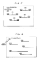
- Fig. 17 is a schematic diagram for illustrativelying the cursor move procedure according to a sixth embodiment of the present invention which is a modification of the third embodiment described previously.
- the teaching of the invention incarnated in the sixth embodiment there are provided in addition to the start and end positions D(1) and I(5), D(2) and I(6), D(3) and I(7), and D(4) and I(8) defining the blank regions overlying the line segments 150 to 153, respectively, those positions mentioned below.
- a common start position D(5, 6, 7, 8) which is a common destination to which the cursor can be moved from the end positions I(5), I(6), I(7) and I(8) and the individual end positions I(1), I(2), I(3) and I(4) which can be reached from the common start position through at least a single operation of the cursor move key and which are paired with the start positions D(1), D(2), D(3) and D(4) of the individual blank regions, respectively.
- the cursor when the cursor arrives at the position I(5) as the result of the character input operation or through the actuation of a cursor move key, the cursor is automatically moved back to the common start position. In other words, the cursor can be moved from the common start position D(5, 6, 7, 8) to any desired one of the blank regions through at least the single key operation.
- the regions overlying the lines 150 to 153 define the first blank regions in which desired character data are to be written, while the regions lying between the common start position and respective end positions I(1), I(2), I(3) and I(4) define the second blank regions.
- the method and the apparatus for realizing the instant embodiment are similar to those of the third embodiment described hereinbefore. Accordingly, description thereof will be unnecessary.
- Fig. 18 is a schematic diagram for illustrativelying the cursor move control according to a seventh embodiment of the invention. This embodiment corresponds to a combination of the first and third embodiments of the invention.
- a common end position I(1, 2, 3, 4, 5) 1 enclosed with a circle and a start position shown enclosed with a rectangle are provided at a same location.
- depression of a selected one of the ten keys (digit keys) "1", “2”, “3”, “4" and "5" causes the cursor to be automatically moved to the corresponding one of the start positions D(1), D(2), D(3), D(4) and D(5).
- the cursor upon depression of the TAB key or the BACK TAB key, the cursor is moved to the start position 1 enclosed with the rectangle. Accordingly, by depressing a selected or desired one of the ten keys "1" to "5", the cursor is moved to the corresponding start position.
- Figs. 19 to 23 show an eighth embodiment of the present invention.
- the cursor move control is carried out by regarding two given discrete points to be one position. More specifically, a pair of symbolic characters are set for the two different points on the screen of the display unit which are regarded to be one and the same position, wherein upon positioning of the cursor on one of the symbolic characters, the cursor is moved to the position of the counterpart symbolic character which is paired with the abovementioned one character.
- the instant embodiment is characterized by symbolic character input means for inputting in correspondence relation with the display screen the pairs of symbolic characters each indicating two given points on the display screen which are logically regarded to lie at a same position, position storage means for storing the positional information of each of the abovementioned symbolic characters, first cursor move control means for controlling the move of the cursor on the display screen in predetermined directions in accordance with the cursor move command information supplied from cursor move command means, and second cursor move control means for reading the content of the position storage means and detecting coincidence between a destination position to which the cursor is to be moved and one position of the abovementioned symbolic characters to thereby move the cursor to the position of the counterpart symbolic character paired with the one symbolic character mentioned above.
- the corresponding positional information is stored in the positional information storage means.
- the cursor in response to the command issued by the cursor move command means, the cursor is moved on the display screen in a predetermined direction under the control of the first cursor move control means.
- the destination of the cursor move controlled by the first cursor move control means is monitored or supervised by the second cursor move control means, wherein upon occurrence of coincidence between the position of one symbolic character and that of the destination, the second cursor move control means moves the cursor to the position of the counterpart symbolic character which is set in a pair with the one symbolic character mentioned above.
- the cursor when the cursor is moved to one of the symbolic character positions, it is instantaneously moved to the position of the counterpart symbolic character position paired with the one symbolic character position.
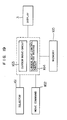
- Fig. 19 is a block diagram showing a general arrangement of the cursor move control apparatus according to the eighth embodiment of the present invention.
- reference numeral 166 denotes a display unit such as a cathode ray tube (CRT) or the like
- 161 denotes a selector circuit for selecting one from the cursor and a plurality of cursor move control characters as the object to be moved
- numeral 165 denotes a storage circuit for storing the positional information of the cursor and the plurality of the cursor move control characters.
- reference numeral 164 denotes a cursor move circuit which responds to the selection of the cursor move control character by the selector circuit 161 for thereby arithmetically determining the next position for displaying the character in accordance with the move command information supplied prom the move command circuit 162 and the positional information set and stored in the storage circuit 165 and moving the cursor move control character displayed on the display 3 to the determined next position.
- Numeral 163 denotes a cursor move circuit which responds to the selection of the cursor by the selector circuit 161 for thereby arithmetically determines or calculates the next position at which the cursor is to be displayed and moving the cursor displayed on the screen of the display unit 3 to the calculated position in accordance with the move command information obtained from the move command circuit 162, the positional information stored in the storage circuit 165 and the position information of the plurality of cursor control characters.
- the calculation of the destination to which the cursor is to be moved is made on the basis of the current cursor position and the information indicating the destination. In that case, if the cursor move control character happens to be located at the position of the destination as calculated, the cursor move circuit 163 performs such control operation that the cursor is moved to the position of the counterpart cursor move control character which is paired with the abovementioned character.
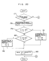
- Fig. 20 is a flow chart for illustrating in detail the cursor move outlined above.
- the position (x, Y) at which the cursor display is to be generated is arithmetically determined at a step 178.
- the positions (X1, Y1) and (X2, Y2) at which the cursor move control characters are being displayed are collated with the position (X, Y) at which the cursor is next to be displayed (at steps 179, 180).
- the position (X, Y) where the cursor is to be displayed is same as the character position (X1, Y1)
- the position (X, Y) where the cursor is to be displayed is altered to the position (X2, Y2) of the counterpart cursor move control character at a step 181.
- the cursor position (X, Y) to be displayed is altered to the position (X1, Y1) of the counterpart cursor move control character.
- the alteration of the position (X, Y) mentioned above is not validated.
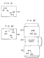
- Fig. 21 is a schematic diagram illustrating a manner in which the cursor is moved in association with the cursor move control characters (hereinafter referred to as the cursor holes). It is assumed that the positions of the cursor holes 196 and 197 are being displayed on the screen 194 and that the cursor located at the position 195 is moved to the right through depression of the right-heading arrow key. When the cursor has reached the cursor hole position 196, it is then moved toward the other cursor hole position 197 to attain the position 198. Selection of the object to be moved is realized through corresponding keyboard operation for selecting one from the cursor and the plural cursor holes.
- Fig. 22 is a schematic diagram illustrating a manner in which the cursor hole is moved.
- the cursor holes are being displayed at the positions 200 and 201 on the screen 199.
- the cursor hole at the position 200 is selected as the object to be moved through the corresponding input operation of the keyboard, it is then possible to move the selected cursor hole by depressing the arrow (cursor) keys or other.
- the cursor hole at the position 200 can be discriminated from the other by displaying that cursor hole in a color or blink.
- the cursor hole can be moved from the position 200 to a position 202 by operating several times the right-heading arrow key and the up-heading arrow key as in the case of validating the ordinary cursor move.
- Fig. 23 is a schematic diagram for illustrating the cursor move performed by making use of the cursor hole function in the course of the creation of sentences with a word processor or the like.
- reference numeral 203 designates a text being currently edited, wherein a start portion of the text is displayed on the screen 204.
- only one cursor hole position 207 makes appearance.
- this cursor hole is not set at a fixed position on the display screen but at a certain position in the text.
- the counterpart cursor hole paired with the abovementioned cursor hole is located at a position toward the end of the text.
- the pair of the cursor holes can not simultaneously be viewed in one and the same picture frame.
- the display is changed over to a picture frame 205 because of the move of the cursor to the cursor hole positioned toward the end of the text.
- the picture frame 205 is dimensioned such that the last mentioned cursor hole can be displayed at an appropriate position 208 in the renewed picture frame 205.
- the cursor is moved to a position 209 to be displayed.
- the symbolic characters or the cursor holes are not limited to the shapes as shown but many other shapes may be used, as described herein strictlybefore.
- a cursor move control which facilitates the cursor move manipulation, allowing the cursor move between two distanced points to be performed within a short period, thus enhancing the manipulatability of the cursor.
- OS operating system
- AP application programs
- the operating system plays roles of making decision for the inputs through the keyboard, displaying the results of processing on the CRT display screen and serving for management of hardware such as efficient allocation of the memories.
- the application program is software such as a word processing program, edition program or the like and usually adapted to perform processings by making use of the functions of the operating system instead of controlling directly the hardware.
- the buffer content translation or conversion processing now under consideration is implemented in the form of software which operates in response to the key input processing performed by the application program.
- the former buffer translation processing loses its function upon completion of execution of the relevant application program.
- the second mentioned buffer translation processing is capable of maintaining its function even after the completed execution of the application program. In other words, the former can provide the same function for given application programs.
- the content of the registration table set union execution of a preceding application program will be lost whenever the table content is updated by an application program activated subsequently.
- the application program is, for example, a word processor program
- the application program For performing the key input processing, the application program usually issues a key input request to the operating system to receive the key data. Upon detection of the key input request issued by the application program, the operating system checks the content of the key buffer and fetches one start key data therefrom, when the key data are stored in the key buffer, the fetched data being then transferred to the application program.
- the translation processing according to the invention intervenes between the application program and the operating system for detecting the key input request from the application program in precedence to the operating system to thereby execute the translation processing.
- the key buffer content is checked in precedence to execution of the processing by the operating system, wherein when the start data of the key buffer is the key data to be subjected to the translation processing, the content of the key buffer is rewritten. Thereafter, the function of the operating system is validated for fetching the one start data from the key buffer to transfer it to the application program.
- Fig. 26 is a block diagram showing a general arrangement of the data processing apparatus such as a conventional word processor or the like
- Fig. 27 shows an arrangement for the key buffer content translation processing according to the invention.
- a key of the keyboard 1 when a key of the keyboard 1 is depressed, key data 201 inputted thereby is sent out from the keyboard 1 and received by the operating system 202 to be placed in the key buffer 203 which can store therein a plurality of key data.
- the key data are stored in the key buffer without being lost, even when the key input request 204 is delayed in the timing of issuing the same, which may take place, for example, in case a key is actuated rapidly in succession.
- the foregoing applies in common to both arrangements shown in Figs. 26 and 27.
- the operating system 202 checks, first of all, the content of the key buffer 203 to fetch the key data 206, if present, the key data being then transferred to the application program 205.
- the key request 207 issued by the application program 205 is detected by the translation processing module 202 according to the invention in precedence to the operating system 202 to thereby check the content of the key buffer 203.
- the data to be subsequently read out from the key buffer 203 (the start data of the key buffer) is the key data to be subjected to the translation processing according to the invention, translation of the key data is effected to rewrite the content of the key buffer.
- the translation processing module 202 issues the key input request 208 to the operating system to receive the key data 209 therefrom. The received data 209 is then transferred to the application program as the key data 210.
Landscapes
- Engineering & Computer Science (AREA)
- General Engineering & Computer Science (AREA)
- Theoretical Computer Science (AREA)
- Human Computer Interaction (AREA)
- Physics & Mathematics (AREA)
- General Physics & Mathematics (AREA)
- Input From Keyboards Or The Like (AREA)
- Digital Computer Display Output (AREA)
- User Interface Of Digital Computer (AREA)
- Controls And Circuits For Display Device (AREA)
Applications Claiming Priority (2)
| Application Number | Priority Date | Filing Date | Title |
|---|---|---|---|
| JP277250/88 | 1988-11-04 | ||
| JP27725088 | 1988-11-04 |
Publications (2)
| Publication Number | Publication Date |
|---|---|
| EP0367290A2 true EP0367290A2 (fr) | 1990-05-09 |
| EP0367290A3 EP0367290A3 (fr) | 1991-07-24 |
Family
ID=17580908
Family Applications (1)
| Application Number | Title | Priority Date | Filing Date |
|---|---|---|---|
| EP19890120405 Withdrawn EP0367290A3 (fr) | 1988-11-04 | 1989-11-03 | Méthode pour commander le déplacement d'un curseur et appareil pour sa mise en oeuvre |
Country Status (2)
| Country | Link |
|---|---|
| EP (1) | EP0367290A3 (fr) |
| JP (1) | JPH02262695A (fr) |
Cited By (1)
| Publication number | Priority date | Publication date | Assignee | Title |
|---|---|---|---|---|
| EP0464742A3 (en) * | 1990-07-02 | 1992-05-27 | Xerox Corporation | Graphics display system with improved dynamic menu selection |
Families Citing this family (1)
| Publication number | Priority date | Publication date | Assignee | Title |
|---|---|---|---|---|
| JP2008176577A (ja) * | 2007-01-18 | 2008-07-31 | Sony Computer Entertainment Inc | 情報表示システム、情報表示方法及びプログラム |
Family Cites Families (3)
| Publication number | Priority date | Publication date | Assignee | Title |
|---|---|---|---|---|
| EP0092218B1 (fr) * | 1982-04-21 | 1987-04-08 | Siemens Aktiengesellschaft | Méthode et arrangement pour imprimer des formulaires dans une station de texte |
| JPS60125885A (ja) * | 1983-12-13 | 1985-07-05 | 沖電気工業株式会社 | カ−ソル移動方法 |
| JP2503423B2 (ja) * | 1986-07-15 | 1996-06-05 | ブラザー工業株式会社 | 入力制御装置 |
-
1989
- 1989-11-02 JP JP1284745A patent/JPH02262695A/ja active Pending
- 1989-11-03 EP EP19890120405 patent/EP0367290A3/fr not_active Withdrawn
Cited By (1)
| Publication number | Priority date | Publication date | Assignee | Title |
|---|---|---|---|---|
| EP0464742A3 (en) * | 1990-07-02 | 1992-05-27 | Xerox Corporation | Graphics display system with improved dynamic menu selection |
Also Published As
| Publication number | Publication date |
|---|---|
| EP0367290A3 (fr) | 1991-07-24 |
| JPH02262695A (ja) | 1990-10-25 |
Similar Documents
| Publication | Publication Date | Title |
|---|---|---|
| US5481278A (en) | Information processing apparatus | |
| EP0243925B1 (fr) | Système d'entrée d'instructions pour un ordinateur électronique | |
| KR100197037B1 (ko) | 정보 처리 장치 및 정보 처리 방법 | |
| US6938220B1 (en) | Information processing apparatus | |
| US4860372A (en) | Real time handwritten character input system | |
| US5091866A (en) | Information processing apparatus displaying multiple windows and distinguishing indicia | |
| US4692858A (en) | Visual interface between user and computer system | |
| US5502803A (en) | Information processing apparatus having a gesture editing function | |
| EP0740245B1 (fr) | Méthode d'entrée de données manuscrites et de commandes de geste et appareil | |
| JPH06131110A (ja) | 情報処理装置 | |
| JP4077959B2 (ja) | 文字処理装置及びその方法、及びそのプログラムを記憶した記憶媒体 | |
| EP0367290A2 (fr) | Méthode pour commander le déplacement d'un curseur et appareil pour sa mise en oeuvre | |
| EP0853271A1 (fr) | Méthode d'engendrement d'une fonction d'une unité de traitement d'information et système de lecture de coordonnées | |
| EP0383306B1 (fr) | Appareil et procédé de traitement de données | |
| JPH06131109A (ja) | 情報処理装置 | |
| JP2738851B2 (ja) | 複数カーソルによる入力データ処理表示方法 | |
| JP2637440B2 (ja) | カーソル制御方式 | |
| JP2851834B2 (ja) | 情報処理装置 | |
| JP3198754B2 (ja) | Cadシステム用図形指示受取装置 | |
| JP2703608B2 (ja) | 文書処理方法及び装置 | |
| JP2578747B2 (ja) | 手書情報処理方法 | |
| JPH0766381B2 (ja) | 漢字処理装置 | |
| JP3358311B2 (ja) | 表処理装置 | |
| JPH1055431A (ja) | 画像処理装置 | |
| JPH02301862A (ja) | 文書作成装置 |
Legal Events
| Date | Code | Title | Description |
|---|---|---|---|
| PUAI | Public reference made under article 153(3) epc to a published international application that has entered the european phase |
Free format text: ORIGINAL CODE: 0009012 |
|
| AK | Designated contracting states |
Kind code of ref document: A2 Designated state(s): DE FR GB IT |
|
| 17P | Request for examination filed |
Effective date: 19901122 |
|
| PUAL | Search report despatched |
Free format text: ORIGINAL CODE: 0009013 |
|
| AK | Designated contracting states |
Kind code of ref document: A3 Designated state(s): DE FR GB IT |
|
| STAA | Information on the status of an ep patent application or granted ep patent |
Free format text: STATUS: THE APPLICATION HAS BEEN WITHDRAWN |
|
| 18W | Application withdrawn |
Withdrawal date: 19920512 |