EP0366876A1 - Abgasbehandlungsapparat - Google Patents
Abgasbehandlungsapparat Download PDFInfo
- Publication number
- EP0366876A1 EP0366876A1 EP89113902A EP89113902A EP0366876A1 EP 0366876 A1 EP0366876 A1 EP 0366876A1 EP 89113902 A EP89113902 A EP 89113902A EP 89113902 A EP89113902 A EP 89113902A EP 0366876 A1 EP0366876 A1 EP 0366876A1
- Authority
- EP
- European Patent Office
- Prior art keywords
- exhaust gas
- electrodes
- reaction vessel
- cylindrical
- flat plate
- Prior art date
- Legal status (The legal status is an assumption and is not a legal conclusion. Google has not performed a legal analysis and makes no representation as to the accuracy of the status listed.)
- Granted
Links
- 239000007789 gas Substances 0.000 claims abstract description 242
- 238000006243 chemical reaction Methods 0.000 claims abstract description 164
- QGZKDVFQNNGYKY-UHFFFAOYSA-N Ammonia Chemical compound N QGZKDVFQNNGYKY-UHFFFAOYSA-N 0.000 claims abstract description 106
- MWUXSHHQAYIFBG-UHFFFAOYSA-N nitrogen oxide Inorganic materials O=[N] MWUXSHHQAYIFBG-UHFFFAOYSA-N 0.000 claims abstract description 60
- 229910021529 ammonia Inorganic materials 0.000 claims abstract description 52
- 229910052815 sulfur oxide Inorganic materials 0.000 claims abstract description 42
- XTQHKBHJIVJGKJ-UHFFFAOYSA-N sulfur monoxide Chemical class S=O XTQHKBHJIVJGKJ-UHFFFAOYSA-N 0.000 claims abstract description 19
- 239000000615 nonconductor Substances 0.000 claims abstract description 4
- 239000003989 dielectric material Substances 0.000 claims description 12
- 239000004020 conductor Substances 0.000 claims description 9
- 230000002093 peripheral effect Effects 0.000 claims description 8
- 239000012530 fluid Substances 0.000 claims description 7
- GQPLMRYTRLFLPF-UHFFFAOYSA-N Nitrous Oxide Chemical compound [O-][N+]#N GQPLMRYTRLFLPF-UHFFFAOYSA-N 0.000 description 26
- 238000002485 combustion reaction Methods 0.000 description 18
- 238000005192 partition Methods 0.000 description 18
- 239000000428 dust Substances 0.000 description 14
- 239000001272 nitrous oxide Substances 0.000 description 13
- 239000000203 mixture Substances 0.000 description 11
- 239000011521 glass Substances 0.000 description 8
- 238000010586 diagram Methods 0.000 description 7
- 239000002245 particle Substances 0.000 description 7
- 238000010891 electric arc Methods 0.000 description 6
- RYGMFSIKBFXOCR-UHFFFAOYSA-N Copper Chemical compound [Cu] RYGMFSIKBFXOCR-UHFFFAOYSA-N 0.000 description 5
- 229910052802 copper Inorganic materials 0.000 description 5
- 239000010949 copper Substances 0.000 description 5
- 230000000694 effects Effects 0.000 description 5
- 150000002500 ions Chemical class 0.000 description 5
- XAGFODPZIPBFFR-UHFFFAOYSA-N aluminium Chemical compound [Al] XAGFODPZIPBFFR-UHFFFAOYSA-N 0.000 description 4
- 229910052782 aluminium Inorganic materials 0.000 description 4
- 229910002089 NOx Inorganic materials 0.000 description 3
- VYPSYNLAJGMNEJ-UHFFFAOYSA-N Silicium dioxide Chemical compound O=[Si]=O VYPSYNLAJGMNEJ-UHFFFAOYSA-N 0.000 description 3
- 239000011148 porous material Substances 0.000 description 3
- IJGRMHOSHXDMSA-UHFFFAOYSA-N Atomic nitrogen Chemical compound N#N IJGRMHOSHXDMSA-UHFFFAOYSA-N 0.000 description 2
- 239000000919 ceramic Substances 0.000 description 2
- 238000006477 desulfuration reaction Methods 0.000 description 2
- 230000023556 desulfurization Effects 0.000 description 2
- 238000007599 discharging Methods 0.000 description 2
- 230000005684 electric field Effects 0.000 description 2
- 238000000034 method Methods 0.000 description 2
- 229910052573 porcelain Inorganic materials 0.000 description 2
- 230000008569 process Effects 0.000 description 2
- 230000001737 promoting effect Effects 0.000 description 2
- XLYOFNOQVPJJNP-UHFFFAOYSA-N water Substances O XLYOFNOQVPJJNP-UHFFFAOYSA-N 0.000 description 2
- PNEYBMLMFCGWSK-UHFFFAOYSA-N aluminium oxide Inorganic materials [O-2].[O-2].[O-2].[Al+3].[Al+3] PNEYBMLMFCGWSK-UHFFFAOYSA-N 0.000 description 1
- QVGXLLKOCUKJST-UHFFFAOYSA-N atomic oxygen Chemical compound [O] QVGXLLKOCUKJST-UHFFFAOYSA-N 0.000 description 1
- 229910010293 ceramic material Inorganic materials 0.000 description 1
- 229910052681 coesite Inorganic materials 0.000 description 1
- 229910052593 corundum Inorganic materials 0.000 description 1
- 229910052906 cristobalite Inorganic materials 0.000 description 1
- 230000003009 desulfurizing effect Effects 0.000 description 1
- 238000009792 diffusion process Methods 0.000 description 1
- 239000012717 electrostatic precipitator Substances 0.000 description 1
- 230000002708 enhancing effect Effects 0.000 description 1
- -1 for example Substances 0.000 description 1
- 238000004817 gas chromatography Methods 0.000 description 1
- XLYOFNOQVPJJNP-ZSJDYOACSA-N heavy water Substances [2H]O[2H] XLYOFNOQVPJJNP-ZSJDYOACSA-N 0.000 description 1
- 230000006872 improvement Effects 0.000 description 1
- 229910010272 inorganic material Inorganic materials 0.000 description 1
- 239000011147 inorganic material Substances 0.000 description 1
- 239000011810 insulating material Substances 0.000 description 1
- 239000000463 material Substances 0.000 description 1
- 230000007246 mechanism Effects 0.000 description 1
- 230000004048 modification Effects 0.000 description 1
- 238000012986 modification Methods 0.000 description 1
- 230000007935 neutral effect Effects 0.000 description 1
- 229910052757 nitrogen Inorganic materials 0.000 description 1
- 229910000069 nitrogen hydride Inorganic materials 0.000 description 1
- 239000001301 oxygen Substances 0.000 description 1
- 229910052760 oxygen Inorganic materials 0.000 description 1
- 230000004044 response Effects 0.000 description 1
- 239000000377 silicon dioxide Substances 0.000 description 1
- 235000012239 silicon dioxide Nutrition 0.000 description 1
- 125000006850 spacer group Chemical group 0.000 description 1
- 230000006641 stabilisation Effects 0.000 description 1
- 238000011105 stabilization Methods 0.000 description 1
- 230000000087 stabilizing effect Effects 0.000 description 1
- 229910052682 stishovite Inorganic materials 0.000 description 1
- 229910052905 tridymite Inorganic materials 0.000 description 1
- 229910001845 yogo sapphire Inorganic materials 0.000 description 1
- 229910052845 zircon Inorganic materials 0.000 description 1
- GFQYVLUOOAAOGM-UHFFFAOYSA-N zirconium(iv) silicate Chemical compound [Zr+4].[O-][Si]([O-])([O-])[O-] GFQYVLUOOAAOGM-UHFFFAOYSA-N 0.000 description 1
Images


Classifications
-
- B—PERFORMING OPERATIONS; TRANSPORTING
- B01—PHYSICAL OR CHEMICAL PROCESSES OR APPARATUS IN GENERAL
- B01D—SEPARATION
- B01D53/00—Separation of gases or vapours; Recovering vapours of volatile solvents from gases; Chemical or biological purification of waste gases, e.g. engine exhaust gases, smoke, fumes, flue gases, aerosols
- B01D53/34—Chemical or biological purification of waste gases
- B01D53/46—Removing components of defined structure
- B01D53/60—Simultaneously removing sulfur oxides and nitrogen oxides
-
- B—PERFORMING OPERATIONS; TRANSPORTING
- B01—PHYSICAL OR CHEMICAL PROCESSES OR APPARATUS IN GENERAL
- B01D—SEPARATION
- B01D53/00—Separation of gases or vapours; Recovering vapours of volatile solvents from gases; Chemical or biological purification of waste gases, e.g. engine exhaust gases, smoke, fumes, flue gases, aerosols
- B01D53/32—Separation of gases or vapours; Recovering vapours of volatile solvents from gases; Chemical or biological purification of waste gases, e.g. engine exhaust gases, smoke, fumes, flue gases, aerosols by electrical effects other than those provided for in group B01D61/00
-
- Y—GENERAL TAGGING OF NEW TECHNOLOGICAL DEVELOPMENTS; GENERAL TAGGING OF CROSS-SECTIONAL TECHNOLOGIES SPANNING OVER SEVERAL SECTIONS OF THE IPC; TECHNICAL SUBJECTS COVERED BY FORMER USPC CROSS-REFERENCE ART COLLECTIONS [XRACs] AND DIGESTS
- Y02—TECHNOLOGIES OR APPLICATIONS FOR MITIGATION OR ADAPTATION AGAINST CLIMATE CHANGE
- Y02A—TECHNOLOGIES FOR ADAPTATION TO CLIMATE CHANGE
- Y02A50/00—TECHNOLOGIES FOR ADAPTATION TO CLIMATE CHANGE in human health protection, e.g. against extreme weather
- Y02A50/20—Air quality improvement or preservation, e.g. vehicle emission control or emission reduction by using catalytic converters
Definitions
- the present invention relates an apparatus for denitrating and/or desulfurizing exhaust gas discharged from boilers for power plants, diesel engines, gas turbines, various kinds of combustion furnaces, etc. by utilization of a glow-discharge plasma.
- Figs. 32 and 33 show the arrangement of a typical conventional exhaust gas treating apparatus that employs a glow-discharge plasma.
- the prior art will next be explained by way of an example in which NO x in exhaust gas from a diesel engine is treated by the illustrated apparatus.
- exhaust gas from a diesel engine 01 is introduced into a plasma reaction vessel 05 through an exhaust pipe 02 via an exhaust pipe 04 of a cyclone collector 03.
- the plasma reaction vessel 05 has an internal electrode 010 disposed inside a cylindrical glass reaction vessel 09, an external electrode 011 disposed outside the reaction vessel 09, and a power supply 06 for applying a glow-discharge voltage between the internal and external electrodes 010 and 011.
- the exhaust gas introduced into the plasma reaction vessel 05 is formed into a plasma in the glow- discharge region to remove NO x from the exhaust gas on the basis of the following principle.
- NO x causes the following chemical reactions: 2NO2 ⁇ 2NO + O2 (1) 2NO + O2 ⁇ N2 + 2O2 (2)
- the plasma is an ionized gas mixture of excited molecules, excited atoms, free radicals, ions and neutral particles which is generated by collision of high-energy electrons accelerated by an external electric field with gas molecules.
- NO x which are given an energy of from several eV to several tens of eV changes into chemically active species and cause complicated reactions to become N2 and O2.
- the exhaust gas from an engine is formed into a plasma by utilization of the atmospheric-pressure glow-discharge phenomenon as described above to treat, for example, NO and NO2, it is possible to attain an NO x removal rate of 80 to 90% when the concentration of (NO+NO2) is in the range of from about 50 to 200ppm, the flow rate of exhaust gas is in the range of from about 30 to 60l/min and the plasma generating power, that is, the power supplied from the power supply 06, is in the range of several W to several tens of W.
- the above-described apparatus has heretofore been utilized as being a public nuisance countermeasure for apparatuses accompanied with various kinds of combustion, for example, boilers, gas turbines and diesel engines.
- the prior art utilizes a glow-discharge plasma reaction chamber which is arranged such that the exhaust gas axially moves through the area defined between a rod-shaped internal electrode and a cylindrical external electrode with a cylindrical glass vessel interposed therebetween, the amount of exhaust gas treated is limited by the cross-sectional area between the internal and external electrodes, that is, the spacing between the two electrodes. Therefore, the prior art has the following problems:
- an exhaust gas treating apparatus for treating an exhaust gas containing nitrogen oxides and/or sulfur oxides by means of a glow-discharge plasma which is capable of removing nitrogen oxides and/or sulfur oxides at high rate even if the flow rate of exhaust gas is relatively high.
- the present invention provides the following means:
- the present invention provides an exhaust gas treating apparatus for making nitrogen oxides and/or sulfur oxides contained in exhaust gas harmless by the use of a glow-discharge plasma, comprising: a cylindrical reaction vessel both ends of which are open and which is made of an electrical insulator; a plurality of porous electrodes provided inside the reaction vessel in such a manner that the planes of the electrodes extend substantially perpendicular to the axis of the reaction vessel; a porous dielectric member installed between each pair of adjacent porous electrodes with a predetermined space provided between the same and one of the two electrodes; a power supply for applying a voltage for glow discharge to the porous electrodes; and an ammonia supply means connected to an inlet pipe of the reaction vessel.
- the present invention provides an exhaust gas treating apparatus that utilizes a glow discharge plasma, comprising: a plurality of flat plate electrodes and a plurality of sawtooth electrodes each constituted by a flat plate with corrugated surfaces, the flat plate and sawtooth electrodes being disposed alternately and parallel to each other; and a power supply connected to the flat plate and sawtooth electrodes; wherein a fluid which is to be treated is arranged to flow between each pair of adjacent flat plate and sawtooth electrodes, preferably in a direction perpendicular to the edges of the crests of the corrugations formed on the sawtooth electrodes.
- the present invention provides an exhaust gas treating apparatus having the above-described flat plate and sawtooth electrodes, further including a flate plate made of a dielectric material which is disposed between each pair of adjacent sawtooth and flat plate electrodes and in contact with the flat plate electrode.
- the present invention provides an exhaust gas treating apparatus having the above-described flat plate and sawtooth electrodes, wherein there are provided a plurality of flat plate electrodes each sandwiched between flat dielectric plates and a plurality of sawtooth electrodes each constituted by a flat plate with corrugated surfaces, the flat plate and sawtooth electrodes being alternately disposed; a voltage is applied between the flat plate and sawtooth electrodes; and a fluid which is to be treated is arranged to flow between each pair of adjacent flat plate and sawtooth electrodes.
- the present invention provides an exhaust gas treating apparatus for treating nitrogen oxides and/or sulfur oxides contained in exhaust gas by the use of a glow-discharge plasma, comprising: a cylindrical reaction vessel both ends of which are closed and which is made of a dielectric material, the reaction vessel having openings provided in the side wall; a cylindrical internal electrode coaxially extending through the reaction vessel and having a plurality of bores provided in the peripheral wall, the internal electrode being supplied with exhaust gas mixed with ammonia; an external electrode provided in such a manner as to surround the outer periphery of the reaction vessel; an exhaust gas outlet or outlets extending through the external electrode; and means for applying a voltage for glow discharge between the internal and external electrodes.
- the present invention provides an exhaust gas treating apparatus as defined in (e), comprising: a cylindrical reaction vessel made of a dielectric material and having a plurality of bores for gas passage provided in the side wall; a first cylindrical electrode made of an electrical conductor and having a plurality of bores for gas passage provided in the side wall, the first cylindrical electrode covering the side wall of the cylindrical reaction vessel; a second cylindrical electrode made of an electrical conductor, the second cylindrical electrode having threads formed on the outer peripheral surface and a plurality of bores for gas passage provided along the crests and/or roots of the threads, and the second cylindrical electrode being coaxially provided inside the cylindrical reaction vessel; and a power supply connected to the first and second cylindrical electrodes; wherein a plurality of units each comprising the cylindrical reaction vessel and the first and second cylindrical electrodes are disposed parallel to each other and an exhaust gas mixed with ammonia which is to be treated is introduced into the second cylindrical electrodes.
- the present invention provides an exhaust gas treating apparatus as defined in (e), comprising: a cylindrical reaction vessel made of a dielectric material and having a plurality of bores for gas passage provided in the side wall; a first cylindrical electrode made of an electrical conductor and having a plurality of bores for gas passage provided in the side wall, the first cylindrical electrode covering the side wall of the cylindrical reaction vessel; a second cylindrical electrode made of an electrical conductor, the second cylindrical electrode having a plurality of bores for gas passage provided in the side wall, each bore having a cylindrical outward projection provided around it, and the second cylindrical electrode being coaxially provided inside the cylindrical reaction vessel; and a power supply connected to the first and second cylindrical electrodes; wherein a plurality of units each comprising the cylindrical reaction vessel and the first and second cylindrical electrodes are disposed parallel to each other and an exhaust gas mixed with ammonia which is to be treated is introduced into the second cylindrical electrodes.
- an exhaust gas which is to be treated is mixed with a very small amount of ammonia as a buffer gas for promoting chemical reactions and the resulting mixture is introduced into the reaction vessel.
- a glow discharge occurs between the porous electrodes inside the reaction vessel, so that the gas mixture is formed into a plasma.
- nitrogen oxides and/or sulfur oxides actively cause chemical reactions to form N2 and/or S.
- the glow discharge taking place inside the reaction vessel is stabilized by virtue of the porous electrodes.
- porous dielectric member enables a large amount of exhaust gas to come into contact with the plasma at high efficiency.
- the exhaust gas flows between the flat plate and sawtooth electrodes which are generating glow discharge in response to a high voltage applied thereto from the power supply, the exhaust gas being preferably arranged to flow in a direction perpendicular to the edges of the crests of the corrugations formed on the sawtooth electrodes.
- the exhaust gas is activated by the plasma to cause chemical reactions, thus removing nitrogen oxides and sulfur oxides.
- the corrugations formed on the electrode enables a glow discharge to occur easily and also permits an increase in the area of contact with the exhaust gas, which results in an improvement in the exhaust gas treating effectiveness. Since the corrugations cause turbulence in the flow of exhaust gas, ions are diffused and it is therefore possible to suppress generation of an arc discharge.
- a glow-discharge plasma is generated between the flat plate and sawtooth electrodes by application of a voltage and the fluid to be treated is activated by the plasma, so that nitrogen oxides and sulfur oxides contained in the fluid are readily decomposed into nitrogen and oxygen.
- the dielectric plate provided on the surface of the flat plate electrode prevents the glow discharge from changing into an arc discharge. In this way, the exhaust gas is readily treated.
- the means for stabilizing the generation of plasma is constituted by bores which are provided in the peripheral wall of the internal electrode extending through the reaction vessel so as to stabilize the glow discharge.
- a voltage is applied between the internal and external electrodes while a gas containing nitrogen oxides and/or sulfur oxides and ammonia is being discharged from the bores provided in the internal electrode, thereby generating a plasma of the gas mixture.
- an exhaust gas mixed with ammonia flows into the cylindrical reaction vessel through the bores provided in the second cylindrical electrode. Then, the gas is discharged to the outside through the bores respectively provided in the cylindrical reaction vessel and the first cylindrical electrode.
- a glow discharge occurs between the first and second cylindrical electrodes. Accordingly, the gas inside the reaction vessel is formed into a plasma and actively performs chemical reactions. Through the chemical reactions, NO x and SO x contained in the exhaust gas are readily removed.
- the generation of glow discharage is facilitated by the threads formed on the second cylindrical electrode. Since the gas mainly flows in the radial direction, there is no fear of the glow discharge dying and there is no lowering in the treating efficiency even if a large amount of gas is supplied. Further, since bores for gas passage are provided in the discharge section, ions are carried by the gas, so that generation of a spark is suppressed. Accordingly, the glow discharge is maintained stably.
- the present invention thus provides an apparatus which is useful for practical application.
- an exhaust gas mixed with ammonia flows into the cylindrical reaction vessel through the bores provided in the second cylindrical electrode. Then, the gas is discharged to the outside through the bores respectively provided in the cylindrical reaction vessel and the first cylindrical electrode. On the other hand, a glow discharge occurs between the first and second cylindrical electrodes. Accordingly, the gas passing there is formed into a plasma and actively performs chemical reactions. Through the chemical reactions, NO x and SO x contained in the exhaust gas are removed.
- the generation of glow discharage in the cylindrical reaction vessel is facilitated by the cylindrical projections formed on the second cylindrical electrode. Since the gas mainly flows in the radial direction, there is no fear of the glow discharge dying and there is no lowering in the treating efficiency even if a large amount of gas is supplied.
- the present invention thus provides an apparatus which is useful for practical application.
- the reference numeral 1 denotes a general-purpose combustion furnace which is an object of exhaust emission control.
- the reference numeral 3 denotes a dust collector (e.g., cyclone collector), and 2 an exhaust pipe for carrying the exhaust gas from the combustion furnace 1 to the dust collector 3. In the dust collector 3, particles that are contained in the exhaust gas are removed.
- the reference numeral 5 denotes a plasma reaction vessel, 4 an exhaust pipe for carrying the exhaust gas from the dust collector 3 to the plasma reaction vessel 5.
- the reference numeral 6 denotes a power supply for applying a plasma generating voltage to the electrodes of the plasma reaction vessel 5, and 7 an outlet pipe for discharging the treated gas which is connected to plasma reaction vessel 5.
- the reference numeral 16 denotes an ammonia supply device that supplies ammonia at a flow rate which may be set as desired within the range of from several l/min to several tens of l/min, and 17 a supply pipe which connects the ammonia supply device 16 to the inlet of the plasma reaction vessel 5.
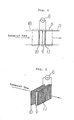
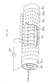
- Fig. 3 is a perspective view showing the arrangement of the plasma reaction vessel 5 shown in Fig. 2.
- the plasma reaction vessel 5 which is a cylindrical vessel both ends of which are open, has a pair of first and second plate-shaped porous electrodes 10 and 11 which are provided therein in such a manner that the planes of the electrodes 10 and 11 extend substantially perpendicular to the axis of the plasma reaction vessel 5.
- the porous electrodes 10 and 11 are connected to the power supply 6.
- a porous dielectric member 9 is installed between the porous electrodes 10 and 11 with a space provided between the same and one of the two electrodes 10 and 11.
- the porous dielectric member 11 is formed from a porous ceramic material.
- the plasma reaction vessel 5 having the above-described arrangement is supplied with a gas mixture of the exhaust gas from the combustion furnace 1 and ammonia from the ammonia supply pipe 17.
- the gas mixture is introduced into the space provided in front of the porous dielectric member 9 through the pores in the porous electrode 10, formed into a plasma by means of a glow discharge, made harmless through the reactions described later, and then discharged to the outside through the respective pores in the porous dielectric member 9 and the porous electrode 11.
- the flow rate of ammonia supplied from the ammonia supply device 16 is in the range of from several l/min to several tens of l/min.
- the above-described plasma is a glow-discharge plasma whereby gas molecules such as ammonia, NO x and SO x are excited and dissociated, thus the gas molecules being brought into a chemically active state.
- gas molecules such as ammonia, NO x and SO x
- the following chemical reactions are caused: NH3+ electronic energy of about 6.4eV ⁇ NH2+H (3) 2NO2+ electronic energy of about 9.5eV ⁇ 2NO+O2 (4) NH2+NO ⁇ N2+H2O (5) 2NH2+SO2 ⁇ S+N2+2H2O (6)
- the plasma is unstable if the flow rate of exhaust gas is higher than about 60l/min, and therefore the upper limit of the flow rate range within which the exhaust gas can be effectively treated is about 100l/min.
- the porous electrodes and the porous dielectric member which have a large number of pores, are installed parallel to a plane perpendicular to the direction of flow of the exhaust gas and it is, therefore, possible to enable a large amount of exhaust gas to come into contact with the plasma in an instant.
- this embodiment it is possible with this embodiment to treat the exhaust gas supplied even at a flow rate of about 1,000l/min without a lowering in the rate of removal of NO x and SO x .
- the apparatus of this embodiment provides a treating capacity which is 10 or more times that of the prior art.
- the number of porous electrodes is two, the number of porous electrodes may be three or more.
- the plasma reaction vessel 5 in the apparatus shown in Fig. 1 is arranged as follows.
- the reference numeral 6 denotes a power supply for supplying electric power for generation of a plasma to a plasma reaction vessel 5.
- the plasma reaction vessel 5 has a duct-shaped casing 111 as shown in Figs. 4 and 5.
- the casing 111 has spaces 111a and 111b provided therein at the front and rear ends, respectively.
- a flat plate anode 101 and a sawtooth cathode 102 constituted by a flat plate having corrugated surfaces are alternately placed horizontally in the casing 111 at predetermined spacings, the cathodes 102 being disposed in such a manner that the edges of the crests of the corrugations extend perpendicular to the direction of flow of the gas, that is, the longitudinal axis.
- the flat plate anodes 101 are disposed so that the uppermost and lowermost layers of the stack of anodes 101 and cathodes 102 are constituted by anodes 101, respectively.
- the power supply 6 is connected to the anodes 101 and the cathodes 102.
- the exhaust gas containing NO x and SO x from the combustion furnace 1 is first supplied to the dust collector 3 where particulate dusts are removed and then mixed with ammonia which is supplied from the ammonia supply device 16 at a flow rate which is about 1% of that of the exhaust gas, before being introduced into the plasma reaction vessel 5.
- the gas mixture of the exhaust gas and ammonia is distributed in the front space 111a so as to pass through the spaces defined between the adjacent flat plate anodes 101 and the corrugated cathodes 102, causing chemical reactions (described later) therein, and thus NO x and SO x being removed. Thereafter, the treated gas comes out to the rear space 111b and flows into the discharge pipe 7.
- a glow discharge occurs between each pair of adjacent anode 101 and cathode 102 by a high voltage applied therebetween, thus generating a plasma of the exhaust gas mixed with ammonia.
- This plasma is a glow-discharge plasma whereby gas molecules such as ammonia, NO x and SO x are excited and dissociated to form a chemically active state, thereby performing denitration and desulfurization represented by the formulae (3) to (6) described in connection with the first embodiment.
- the corrugations of the cathode 102 enable an increase in the area of contact with the exhaust gas mixed with ammonia, thus enhancing the treating efficiency.
- the corrugations also enable a glow discharge to occur easily and cause turbulence in the flow of the exhaust gas, which causes diffusion of ions to suppress generation of an arc discharge. Thus, efficient chemical reactions are maintained.
- Figs. 6 and 7 show NO x (50 to 200ppm) and SO x (about 100ppm) removing conditions attained by this embodiment.
- the chain lines show the results obtained by the prior art, while the solid lines show the results by this embodiment. It will be understood that the exhaust gas treating capacity has markedly increased.
- This embodiment is an exhaust gas treating apparatus which is suitable for treating nitrous oxide (N2O) contained in exhaust gas.
- Exhaust gas from a combustion furnace 201 is carried to a dust collector 203 through an exhaust pipe 202.
- the dust collector 203 which is, for example, a cyclone collector or an electrostatic precipitator, collects particles contained in the exhaust gas.
- the exhaust gas from the dust collector 203 is carried to a dehumidifier 205 through an exhaust pipe 204.
- water contained in the exhaust gas is removed.
- the exhaust gas from the dehumidifier 205 is carried to a plasma reaction vessel 211 through an exhaust pipe 206.
- first and second gas analyzers 209 and 210 are connected to the exhaust pipe 206 and the outlet pipe 207, respectively. These gas analyzers 209 and 210 are, for example, gas chromatographies, for measuring the concentration of N2O gas.
- a power supply 208 supplies a plasma generating power to the plasma reaction vessel 211.
- the plasma reaction vessel 211 has a duct-shaped casing 212.
- the casing 212 has spaces 211a and 211b provided therein at the front and rear ends, respectively.
- a flat plate electrode 300 which is sandwiched between a pair of flat dielectric plates 302 and a sawtooth electrode 301 constituted by a flat plate having corrugated surfaces are alternately placed horizontally in the casing 212 at predetermined spacings, the sawtooth electrodes 301 being disposed in such a manner that the edges of the crests of the corrugations extend parallel to the direction of flow of the gas, that is, the longitudinal axis.
- the flat plate electrodes 300 are disposed so that the uppermost and lowermost layers of the stack of electrodes 300 and 301 are constituted by flat plate electrodes 300, respectively, and the uppermost and lowermost plates 302 are removed.
- the power supply 208 is connected to the electrodes 300 and 301.
- the reference numeral 303 in Fig. 10 denotes mounts each serving also as a spacer, the mounts 303 being made of an insulating material.
- the flat plate electrodes 300 and the sawtooth electrodes 301 are made of a conductor, for example, SUS 304, copper or Al.
- the pitch of the sawtooth corrugations of the electrodes 301 is set at 1 to 5mm and the depth thereof at 0.5 to 5mm with a view to enabling a plasma to be generated easily.
- the dielectric plates 302 are made of an inorganic material which has a dieletric constant of 3 to 10 in the temperature range of from 100 to 600°C and an electric resistivity of 1 x 10¹⁰ to 1 x 10¹⁸ ⁇ cm, for example, quartz glass, aluminous porcelain (Al2O3 ceramics), zircon porcelain or SiO2.
- the exhaust gas containing N2O which is generated from the combustion furnace 201 is carried through the exhaust pipe 202 to the dust collector 203 where particles are removed from the exhaust gas and then the exhaust gas is carried to the dehumidifier 205 through the exhaust pipe 204.
- the dehumidifier 205 water is removed from the exhaust gas so that a plasma will be readily generated.
- the dehumidified gas is then carried through the exhaust pipe 206 to the front space 211a in the plasma reaction vessel 211.
- the concentration of N2O contained in the exhaust gas carried to the plasma reaction vessel 211 is measured with the first gas analyzer 209.
- the N2O concentration was about 80 to 120ppm.
- the exhaust gas carried to the front space 211a in the plasma reaction vessel 211 is then carried to the rear space 211b through a glow-discharge region, that is, an exhaust gas passage 304, which is defined between each pair of adjacent dielectric plate 302 and sawtooth electrode 301.
- a glow-discharge region that is, an exhaust gas passage 304, which is defined between each pair of adjacent dielectric plate 302 and sawtooth electrode 301.
- the exhaust gas that is present in each exhaust gas passage 304 is formed into a plasma. More specifically, when a high electric field is applied to the exhaust gas containing N2O from the power supply 208 with the thickness of each dielectric plate 302 set at a proper value, the exhaust gas is formed into a plasma by means of glow discharge.
- dielectric plates 302 In this embodiment, quarts glass plates having a thickness of 5mm were employed as dielectric plates 302 and the applied voltage was set at 10 to 17KV to obtain a glow-discharge plasma.
- the dielectric plates 302 prevent the glow discharge from becoming an arc discharge.
- the N2O concentation in the exhaust gas outlet pipe 207 is measured with the second gas analyzer 210.
- the N2O concentation was 3 to 5ppm. This means that the N2O gas which first had a concentration of 80 to 120ppm was decomposed substantially completely through the plasma reaction vessel 211.
- the mechanism may be considered as follows.
- the above-described plasma is a glow-discharge plasma of exhaust gas containing N2O gas
- the gas molecules in the exhaust gas are excited or dissociated by collision of electrons.
- a chemical reaction such as that represented by the formula (7) takes place: 2N2O+ electronic energy of about 12.94eV ⁇ 2N2+O2 (7)
- Fig. 11 is a graph showing N2O (80 to 120ppm) removing conditions attained by this embodiment. It will be understood from the figure that an N2O removal rate of 90% or more is obtained in the exhaust gas flow rate range of from 100 to 2,000l/min.
- Fig. 12 is a block diagram showing the general arrangement of this embodiment
- Fig. 13 is a transverse sectional view of the plasma reaction vessel in this embodiment. It should be noted that description of the same members or portions as those in the third embodiment is omitted and members and portions which are different from those in the third embodiment will be mainly explained below.
- Fig. 13 shows the arrangement of electrodes inside the plasma reaction vessel 211′.
- a sawtooth corrugated electrode 301 is provided in the center of the casing 112′, and a pair of flat plate electrodes 300 are provided so as to face both the surfaces, respectively, of the corrugated electrode 301 with a predetermined space.
- a flat plate 302 made of a dielectric material is provided between the sawtooth electrode 301 and each flat plate electrode 300 and in contact with the electrode 300.
- the flat plate electrodes 300 and the sawtooth electrodes 301 are connected to a power supply 208.
- the reference numeral 401 denotes a general-purpose combustion furnace which is an object of exhaust emission control.
- the reference numeral 402 denotes an exhaust pipe for carrying the exhaust gas from the combustion furnace 401 to a dust collector (e.g., cyclone collector) 403. In the dust collector 403, particles that are contained in the exhaust gas are removed.
- the reference numeral 404 denotes an exhaust pipe for carrying the exhaust gas from the dust collector 403 to an inlet pipe 418 of a plasma reactor 405.
- the reference numeral 406 denotes a power supply for applying a plasma generating voltage to the electrodes of the plasma reactor 405.
- the reference numerals 407a and 407b denote exhaust gas outlet pipes which are connected to the plasma reactor 405.
- the reference numeral 416 denotes an ammonia supply device that supplies ammonia at a flow rate which may be set as desired within the range of from several l/min to several tens of l/min, the ammonia being supplied to an exhaust gas inlet pipe 418 through an ammonia supply pipe 417 which is connected to the exhaust pipe 404.
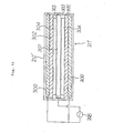
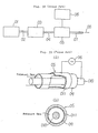
- Fig. 16 is a sectional view taken along the line X-X of Fig. 15.
- a cylindrical internal electrode 410 extends through a cylindrical reaction vessel 409 both ends of which are closed and which has openings in the side wall.
- the internal electrode 410 has a plurality of bores 412 provided in the peripheral wall.
- An external electrode 411 is provided on the outer periphery of the reaction vessel 409 so as to surround it, and a pair of exhaust gas outlet pipes 407a and 407b are connected to the respective openings provided in the side wall of the reaction vessel 409 in such a manner that outlet pipes 407a and 407b extend through the external electrode 411.
- the reaction vessel 409 is made of glass in this embodiment. However, the material for the reaction vessel 409 is not necessarily limited to glass and any desired dielectric material, for example, ceramics, may be used.
- the reference numeral 418 denotes an exhaust gas inlet pipe which is connected to the internal electrode 410 through an electrical insulating pipe 413.
- ammonia is supplied through the ammonia supply pipe 417 to the exhaust pipe 404 where it is mixed with the exhaust gas from the combustion furnace 401.
- the gas mixture is then introduced via the electrical insulating pipe 413 into the reaction vessel 409 through the bores 412 in the internal electrode 410.
- the reaction vessel 409 the gas mixture is made harmless through the above-described reactions caused by a voltage applied to the electrodes from the power supply 406.
- the treated exhaust gas is then discharged to the outside from the exhaust gas outlet pipes 407a and 407b.
- the exhaust gas containing NO x and SO x generated from the combustion furnace 401 is carried through the exhaust pipe 402 to the dust collector 403 where particles are removed from the exhaust gas and the gas is then introduced into the internal electrode 410 through the exhaust pipe 404 and the exhaust gas inlet pipe 418 and the electrical insulating pipe 413 of the plasma reactor 405.
- the exhaust gas enters the reaction vessel 409 through the bores 412 provided in the internal electrode 410 and is then discharged to the outside through the exhaust gas outlet pipes 407a and 407b.
- ammonia is supplied from the ammonia supply device 416 through the ammonia supply pipe 417 and the exhaust gas inlet pipe 418 and introduced into the reaction vessel 409 through the bores 412 in the internal electrode 410 at a flow rate in the range of from several l/min to several tens of l/min.
- This plasma is a glow-discharge plasma whereby gas molecules such as ammonia, NO x and SO x are excited and dissociated to form a chemically active state, thereby performing denitration and desulfurization represented by the formulae (3) to (6) described in connection with the first embodiment.
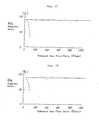
- Figs. 17 and 18 show NO x (50 to 200ppm) and SO x (about 100ppm) removing conditions attained by the apparatus of this embodiment.
- the chain lines show the results obtained by the prior art, while the solid lines show the result obtained by this embodiment.
- Fig. 17 is a graph showing the relationship between the NO x removal rate and the flow rate of the exhaust gas.
- the apparatus of this embodiment is capable of treating exhaust gas even at a flow rate of 1,000l/min without a lowering in the rate of removal of NO x .
- Fig. 18 is a graph showing the relationship between the SO x removal rate and the flow rate of the exhaust gas.
- the apparatus of this embodiment is capable of treating exhaust gas even at a flow rate of 1,000l/min without a lowering in the rate of removal of SO x .
- the apparatus of this embodiment has a treating capacity which is about 10 times that of the prior art.
- the present invention may also be applied to the treatment of an exhaust gas containing only NO x or SO x as a harmful gas component.
- the reference numeral 501 denotes a combustion furnace which is an object of exhaust emission control.
- the exhaust gas from the combustion furnace 501 is carried to a cyclone collector 503 through an exhaust pipe 502.
- the dust collector 503 particles that are contained in the exhaust gas are removed.
- the exhaust gas from the cyclone collector 503 is carried to a plasma reaction vessel (described later) 510 through a cylcone collector exhaust pipe 504.
- An ammonia supply device 505 supplies ammonia at a flow rate which may be set as desired within the range of from several l/min to several tens of l/min to the intermediate portion of the cylcone collector exhaust pipe 504 through an ammonia supply pipe 506.
- the gas that is discharged from the plasma reaction vessel 510 is released to the outside through a discharge pipe 508.
- a power supply 509 supplies electric power for plasma generation to the plasma reaction vessel 510.
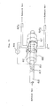
- the plasma reaction vessel 510 has a duct-shaped casing 511.
- Transverse partition walls 511a and 511b are provided in the forward and rearward end portions, respectively, of the casing 511.
- Between the partition walls 511a and 511b are provided a plurality of first cylindrical electrodes 603 each having a cylindrical reaction vessel (described later), the electrodes 603 extending parallel to the axis of the casing 511 (see Fig. 21).
- each first cylindrical electrode 603 is made of aluminum or copper and has a plurality of first bores 603a for gas passage which are provided in the side wall at predetermined spacings.
- a cylindrical reaction vessel 602 made of glass is provided inside the first cylindrical electrode 603 in such a manner that the outer periphery of the reaction vessel 602 is in contact with the inner periphery of the first cylindrical electrode 603.
- the side wall of the reaction vessel 602 is provided with a plurality of bores which are coaxial with the corresponding bores 603a and which have a slightly smaller diameter than that of the bores 603a.
- a second cylindrical electrode 601 made of aluminum or copper is coaxially provided inside the first cylindrical electrode 603.
- the second cylindrical electrode 601 has threads formed on the outer periphery thereof, and a plurality of radial second and third bores 601a and 601b are provided along the roots and crests, respectively, of the threads (see Fig. 23). It is preferable that the second and third bores 601a and 601b have a diameter of from 1 to 5mm, the pitch of the threads be from 1 to 5mm and the depth of the threads be not greater than about 30mm. It should be noted that either second bores 601a or third bores 601b alone may be provided.
- the first and second cylindrical electrodes 603 and 601 are disposed between the partition walls 511a and 511b inside the casing 511 as follows (see Fig. 20):
- the exhaust gas containing NO x and SO x from the combustion furnace 501 is supplied to the cyclone collector 503 where particulate dusts are removed, and the exhaust gas is then mixed with ammonia supplied from the ammonia supply device 505 at a flow rate which is about 1% of that of the exhaust gas.
- the gas mixture is then introduced into the plasma reaction vessel 510.
- the exhaust gas is distributed in the space 510a in front of the forward partition wall 511a so as to enter each second cylindrical electrode 601 through the corresponding bore e and then comes out of the second bores 601a and the third bores 601b into the space within the cylindrical reaction vessel 602 (see Figs. 20 and 22).
- a glow discharge occurs in each cylindrical reaction vessel 602 in respone to a high voltage applied between the first and second cylindrical electrodes 603 and 601, thus generating a plasma of the exhaust gas mixed with ammonia.
- chemical reactions such as those represented by the formulae (3) to (6) described in connection with the first embodiment take place, thus NO x and SO x being removed.
- the exhaust gas emerges into the space inside the casing 511 through the first bores 603a, further emerges into the rear space 510 through the bores f and then flows into the gas discharge pipe 508.
- the glow discharge is maintained without a fear of dying even if the flow rate of exhaust gas which is to be treated is increased higher than in the case where the exhaust gas flows axially as in the prior art. There is no lowering in the removal efficiency, either.
- the glow-discharge region is provided with bores for gas passage, ions are carried by the gas, so that generation of a spark is suppressed.
- the thread-shaped projections on the second cylindrical electrode 603 are provided with a view to enabling a glow discharge to occur easily.
- the reason why the cylindrical reaction vessel 602 made of a dielectric material is disposed between the first and second cylindrical electrodes 603 and 601 and the reason why the diameter of the first bores 601a is greater than that of the bores of the reaction vessel 602 are to control the discharge current so that no arc discharge will be generated.
- Figs. 24 and 25 show NO x (50 to 200ppm) and SO x (about 100ppm) removing conditions attained by this embodiment.
- the chain lines show the results obtained by the prior art, while the solid lines show the results by this embodiment. It will be understood that the exhaust gas treating capacity has increased by a large margin.
- a plasma reaction vessel 710 shown in Fig. 26 is supplied with the exhaust gas and ammonia from the combustion furnace 501 and the ammonia supply device 505, respectively, which are shown in Fig. 19, through the cyclone collector exhaust pipe 504 and then discharged to the outside from the plasma reaction vessel 710 through the exhaust gas discharge pipe 508, in the same way as in the sixth embodiment.
- the power supply 509 shown in Fig. 19 supplies electric power for plasma generation to the plasma reaction vessel 710.
- the plasma reaction vessel 710 has a duct-shaped caing 711.
- Transverse partition walls 711a and 711b are provided in the forward and rearward end portions, respectively, of the casing 711.
- a plurality of reactor units each comprising a cylindrical reaction vessel, a first cylindircal electrode 803 and a second cylindrical electrode 801 (described later), the reactor units extending parallel to the axis of the casing 711 (see Fig. 27).
- each first cylindrical electrode 803 is made of aluminum or copper and has a plurality of first bores 803a for gas passage which are provided in the side wall at predetermined spacings.
- a cylindrical reaction vessel 802 made of glass is provided inside the first cylindrical electrode 803 in such a manner that the outer periphery of the reaction vessel 802 is in contact with the inner periphery of the first cylindrical electrode 803.
- the side wall of the reaction vessel 802 is provided with a plurality of bores which are coaxial with the corresponding bores 803a and which have a slightly smaller diameter than that of the bores 803a.
- a second cylindrical electrode 801 made of aluminum or copper is coaxially provided inside the cylindrical reaction vessel 802.
- a plurality of second bores 801a for gas passage are provided in the side wall of the second cylindrical electrode 801.
- the periphery of each bore 801a is formed in the shape of a cylindrical projection which projects outward (see Fig. 29).
- second bores 801a have a diameter of from 1 to 5mm and the height of the projections is 2 to 4 times the bore diameter.
- the number of first bores 803a is about 1/10 to 1/50 of that of second bores 801a.
- the first and second cylindrical electrodes 803 and 801 are disposed between the partition walls 711a and 711b inside the casing 711 as follows (see Fig. 26):
- the exhaust gas containing NO x and SO x from the combustion furnace is supplied to the cyclone collector where particulate dusts are removed, and the exhaust gas is then mixed with ammonia supplied from the ammonia supply device at a flow rate which is about 1% of that of the exhaust gas.
- the gas mixture is then introduced into the plasma reaction vessel 710.
- the exhaust gas is distributed in the space 710a in front of the forward partition wall 711a so as to enter each second cylindrical electrode 801 through the corresponding bore e and then comes out of the second bores 801a into the space within the cylindrical reaction vessel 802 through the second bores 801a (see Figs. 26 and 28).
- the projections around the second bores 801a are provided with a view to enabling a glow discharge to occur easily.
- the reason why the cylindrical reaction vessel 802 made of a dielectric material is disposed between the first and second cylindrical electrodes 803 and 801 and the reason why the diameter of the first bores 803a is greater than that of the bores of the reaction vessel 802 are to control the discharge current so that no arc discharge will be generated.
- Figs. 30 and 31 show NO x (50 to 200ppm) and SO x (about 100ppm) removing conditions attained by this embodiment.
- the chain lines show the results obtained by the prior art, while the solid lines show the results by this embodiment. It will be understood that the exhaust gas treating capacity has increased by a large margin.
Landscapes
- Chemical & Material Sciences (AREA)
- Engineering & Computer Science (AREA)
- Analytical Chemistry (AREA)
- General Chemical & Material Sciences (AREA)
- Oil, Petroleum & Natural Gas (AREA)
- Chemical Kinetics & Catalysis (AREA)
- Health & Medical Sciences (AREA)
- Biomedical Technology (AREA)
- Environmental & Geological Engineering (AREA)
- Treating Waste Gases (AREA)
Priority Applications (1)
| Application Number | Priority Date | Filing Date | Title |
|---|---|---|---|
| AT89113902T ATE89187T1 (de) | 1988-10-05 | 1989-07-27 | Abgasbehandlungsapparat. |
Applications Claiming Priority (12)
| Application Number | Priority Date | Filing Date | Title |
|---|---|---|---|
| JP129946/88U | 1988-10-05 | ||
| JP129948/88U | 1988-10-05 | ||
| JP129947/88U | 1988-10-05 | ||
| JP12994688 | 1988-10-05 | ||
| JP12994788 | 1988-10-05 | ||
| JP12994888U JPH0611073Y2 (ja) | 1988-10-05 | 1988-10-05 | 脱硝・脱硫装置 |
| JP267184/88 | 1988-10-25 | ||
| JP63267184A JPH02115024A (ja) | 1988-10-25 | 1988-10-25 | 脱亜酸化窒素装置 |
| JP63282566A JPH02131123A (ja) | 1988-11-10 | 1988-11-10 | 排ガス処理装置 |
| JP282566/88 | 1988-11-10 | ||
| JP64012/89U | 1989-06-02 | ||
| JP6401289U JPH02104830U (de) | 1988-10-05 | 1989-06-02 |
Publications (2)
| Publication Number | Publication Date |
|---|---|
| EP0366876A1 true EP0366876A1 (de) | 1990-05-09 |
| EP0366876B1 EP0366876B1 (de) | 1993-05-12 |
Family
ID=27550956
Family Applications (1)
| Application Number | Title | Priority Date | Filing Date |
|---|---|---|---|
| EP89113902A Expired - Lifetime EP0366876B1 (de) | 1988-10-05 | 1989-07-27 | Abgasbehandlungsapparat |
Country Status (2)
| Country | Link |
|---|---|
| EP (1) | EP0366876B1 (de) |
| DE (1) | DE68906508T2 (de) |
Cited By (35)
| Publication number | Priority date | Publication date | Assignee | Title |
|---|---|---|---|---|
| EP0578863A1 (de) * | 1991-01-25 | 1994-01-19 | Takuma Co., Ltd. | Verfahren zur Reduzierung des Stickoxidgehaltes in Gas |
| WO1994003263A1 (en) * | 1992-08-04 | 1994-02-17 | Public Health Laboratory Service Board | Improvements in the conversion of chemical moieties |
| EP0597206A1 (de) * | 1992-10-27 | 1994-05-18 | Dornier Gmbh | Verfahren zur Minderung von Russpartikeln in Abgasströmen |
| EP0608619A1 (de) * | 1993-01-20 | 1994-08-03 | United Kingdom Atomic Energy Authority | Abgasreinigung |
| WO1995031271A1 (de) * | 1994-05-11 | 1995-11-23 | Siemens Aktiengesellschaft | Vorrichtung zur entgiftung von abgasen aus mobilen anlagen |
| WO1997003746A1 (de) * | 1995-07-14 | 1997-02-06 | Siemens Aktiengesellschaft | Verfahren und vorrichtung zur plasmachemischen zersetzung und/oder vernichtung von schadstoffen |
| WO1998000221A1 (en) * | 1996-06-28 | 1998-01-08 | Low Emissions Technologies Research And Development Partnership | Exhaust system with emissions storage device and plasma reactor |
| WO1998048922A1 (de) * | 1997-04-28 | 1998-11-05 | Institut für Niedertemperatur-Plasmaphysik e.V. an der Ernst-Moritz-Arndt-Universität Greifswald | Vorrichtung und verfahren zur zersetzung von schadstoffen in abgasen von verbrennungsprozessen |
| WO1999005400A1 (en) | 1997-07-23 | 1999-02-04 | Aea Technology Plc | Gas purification device |
| EP0885647A3 (de) * | 1997-06-17 | 1999-04-07 | Carl Maria Prof. Dr. Fleck | Vorrichtung zur Dissoziation von im Abgas von Verbrennungskraftmaschinen enthaltenen Stickstoffoxiden |
| WO1999043933A1 (de) | 1998-02-26 | 1999-09-02 | Siemens Aktiengesellschaft | Verfahren und vorrichtung zur abgasreinigung |
| WO1999047242A1 (en) * | 1998-03-18 | 1999-09-23 | Scientific Research Center 'amt' Of Central Research Institute For Materials | Method and device for cleaning combustion exhaust gas using a plasma |
| WO2000001469A1 (en) * | 1998-07-03 | 2000-01-13 | Applied Plasma Physics As | Electrode and reaction chamber for use in generation of non-thermal plasma |
| WO2000029727A1 (en) * | 1998-11-13 | 2000-05-25 | Engelhard Corporation | PLASMA FUEL PROCESSING FOR NOx CONTROL OF LEAN BURN ENGINES |
| WO2000043645A2 (en) | 1999-01-21 | 2000-07-27 | Accentus Plc | Power supply for processing of gaseous media |
| WO2000051714A1 (en) * | 1999-03-02 | 2000-09-08 | Accentus Plc | Plasma-assisted processing of gaseous media |
| WO2000071866A1 (en) * | 1999-05-21 | 2000-11-30 | Accentus Plc | Dielectric barrier gas reactors with non-axial flow |
| US6253544B1 (en) | 1994-05-18 | 2001-07-03 | Lockheed Martin Corporation | Method and apparatus for reducing pollutants |
| EP1114434A1 (de) * | 1998-09-16 | 2001-07-11 | Trustees Of The Stevens Institute Of Technology | Wechselstrom-glühplasmaentladungsvorrichtung mit einer mit gelocthem dielektrikum überzogener elektrode |
| US6264899B1 (en) | 1996-06-28 | 2001-07-24 | Litex, Inc. | Method and apparatus for using hydroxyl to reduce pollutants in the exhaust gases from the combustion of a fuel |
| EP1155599A1 (de) * | 1999-02-01 | 2001-11-21 | Sigma Technologies International, Inc. | Atmosphärische stationäre glimmentladungsplasma |
| US6321531B1 (en) | 1996-12-18 | 2001-11-27 | Litex, Inc. | Method and apparatus for using free radicals to reduce pollutants in the exhaust gases from the combustion of a fuel |
| US6330794B1 (en) | 1996-12-18 | 2001-12-18 | Litex, Inc. | Method and apparatus for using free radicals to reduce pollutants in the exhaust gases from the combustion of a fuel |
| US6357223B1 (en) | 1996-12-18 | 2002-03-19 | Litex, Inc. | Method and apparatus for enhancing the rate and efficiency of gas phase reactions |
| EP1541821A1 (de) * | 2003-12-11 | 2005-06-15 | Peugeot Citroen Automobiles S.A. | Nicht thermischer Plasmareaktor und Kraftfahrzeugabgasanlage mit einem solchen Reaktor |
| DE10355227A1 (de) * | 2003-11-26 | 2005-06-30 | Fricke, Uwe Stefan | Vorrichtung zum Erzeugen wenigstens eines fluiden Reaktionsproduktes aus wenigstens einem fluiden Ausgangsstoff mittels chemischer Reaktion im Plasma dielektrisch behinderter Entladungen |
| WO2007048998A1 (en) * | 2005-10-26 | 2007-05-03 | Edwards Limited | Apparatus for treating a gas stream |
| EP2120514A1 (de) | 2008-05-14 | 2009-11-18 | Electricité de France | Vorrichtung zur Gasbehandlung mit Kaltplasma, entsprechende Anwendungs- und Herstellungsverfahren |
| CN102274680A (zh) * | 2011-07-22 | 2011-12-14 | 广东佳德环保科技有限公司 | 流光放电氨法烟气脱硫脱硝除雾一体化方法 |
| US9532826B2 (en) | 2013-03-06 | 2017-01-03 | Covidien Lp | System and method for sinus surgery |
| US9555145B2 (en) | 2013-03-13 | 2017-01-31 | Covidien Lp | System and method for biofilm remediation |
| EP2434975B1 (de) * | 2008-05-30 | 2018-07-11 | Colorado State University Research Foundation | Plasmavorrichtung für grossflächige oberflächenbehandlung von gewebe |
| WO2020040654A1 (en) * | 2018-08-24 | 2020-02-27 | YELKIN lhar | Method and device for the reduction of contaminants in a plasma reactor, especially contamination by lubricants |
| CN111389196A (zh) * | 2020-03-24 | 2020-07-10 | 安吉旺能再生资源利用有限公司 | 烟气低温等离子协同处理方法及其系统 |
| CN112588092A (zh) * | 2020-11-25 | 2021-04-02 | 肖康 | 一种具有限流功能的脱硫脱硝除尘器 |
Families Citing this family (2)
| Publication number | Priority date | Publication date | Assignee | Title |
|---|---|---|---|---|
| AU2002313279A1 (en) * | 2001-12-21 | 2003-07-09 | Furrex Co., Ltd. | Discharging method for gas decomposition and discharging device for gas decomposition |
| CN102160961A (zh) * | 2011-02-25 | 2011-08-24 | 华北电力大学 | 介质阻挡放电反应器、烟气脱硫脱硝系统及脱硫脱硝工艺 |
Citations (2)
| Publication number | Priority date | Publication date | Assignee | Title |
|---|---|---|---|---|
| EP0158823A2 (de) * | 1984-04-14 | 1985-10-23 | BROWN, BOVERI & CIE Aktiengesellschaft | Verfahren und Vorrichtung zur Reinigung von Abgasen |
| US4650555A (en) * | 1985-10-03 | 1987-03-17 | General Electric Company | Method for corona discharge enhanced flue gas clean-up |
-
1989
- 1989-07-27 DE DE8989113902T patent/DE68906508T2/de not_active Expired - Fee Related
- 1989-07-27 EP EP89113902A patent/EP0366876B1/de not_active Expired - Lifetime
Patent Citations (2)
| Publication number | Priority date | Publication date | Assignee | Title |
|---|---|---|---|---|
| EP0158823A2 (de) * | 1984-04-14 | 1985-10-23 | BROWN, BOVERI & CIE Aktiengesellschaft | Verfahren und Vorrichtung zur Reinigung von Abgasen |
| US4650555A (en) * | 1985-10-03 | 1987-03-17 | General Electric Company | Method for corona discharge enhanced flue gas clean-up |
Non-Patent Citations (1)
| Title |
|---|
| PATENT ABSTRACTS OF JAPAN * |
Cited By (50)
| Publication number | Priority date | Publication date | Assignee | Title |
|---|---|---|---|---|
| EP0578863A1 (de) * | 1991-01-25 | 1994-01-19 | Takuma Co., Ltd. | Verfahren zur Reduzierung des Stickoxidgehaltes in Gas |
| US5324492A (en) * | 1991-01-25 | 1994-06-28 | Takuma Co., Ltd. | Method of reducing nitrogen oxide content in gas |
| WO1994003263A1 (en) * | 1992-08-04 | 1994-02-17 | Public Health Laboratory Service Board | Improvements in the conversion of chemical moieties |
| EP0597206A1 (de) * | 1992-10-27 | 1994-05-18 | Dornier Gmbh | Verfahren zur Minderung von Russpartikeln in Abgasströmen |
| EP0608619A1 (de) * | 1993-01-20 | 1994-08-03 | United Kingdom Atomic Energy Authority | Abgasreinigung |
| US5440876A (en) * | 1993-01-20 | 1995-08-15 | United Kingdom Atomic Energy Authority | Exhaust gas purification |
| WO1995031271A1 (de) * | 1994-05-11 | 1995-11-23 | Siemens Aktiengesellschaft | Vorrichtung zur entgiftung von abgasen aus mobilen anlagen |
| US5746051A (en) * | 1994-05-11 | 1998-05-05 | Siemens Aktiengesellschaft | Device for detoxifying exhaust fumes from mobile equipment |
| US6253544B1 (en) | 1994-05-18 | 2001-07-03 | Lockheed Martin Corporation | Method and apparatus for reducing pollutants |
| WO1997003746A1 (de) * | 1995-07-14 | 1997-02-06 | Siemens Aktiengesellschaft | Verfahren und vorrichtung zur plasmachemischen zersetzung und/oder vernichtung von schadstoffen |
| US5746984A (en) * | 1996-06-28 | 1998-05-05 | Low Emissions Technologies Research And Development Partnership | Exhaust system with emissions storage device and plasma reactor |
| US6264899B1 (en) | 1996-06-28 | 2001-07-24 | Litex, Inc. | Method and apparatus for using hydroxyl to reduce pollutants in the exhaust gases from the combustion of a fuel |
| WO1998000221A1 (en) * | 1996-06-28 | 1998-01-08 | Low Emissions Technologies Research And Development Partnership | Exhaust system with emissions storage device and plasma reactor |
| US6357223B1 (en) | 1996-12-18 | 2002-03-19 | Litex, Inc. | Method and apparatus for enhancing the rate and efficiency of gas phase reactions |
| US6330794B1 (en) | 1996-12-18 | 2001-12-18 | Litex, Inc. | Method and apparatus for using free radicals to reduce pollutants in the exhaust gases from the combustion of a fuel |
| US6321531B1 (en) | 1996-12-18 | 2001-11-27 | Litex, Inc. | Method and apparatus for using free radicals to reduce pollutants in the exhaust gases from the combustion of a fuel |
| WO1998048922A1 (de) * | 1997-04-28 | 1998-11-05 | Institut für Niedertemperatur-Plasmaphysik e.V. an der Ernst-Moritz-Arndt-Universität Greifswald | Vorrichtung und verfahren zur zersetzung von schadstoffen in abgasen von verbrennungsprozessen |
| US6517786B1 (en) | 1997-04-28 | 2003-02-11 | Institute Fuer Niedertemperatur-Plasmaphysik E. V. An Der Ernst-Moritz-Arndt-Universitaet Greifswald | Device and method for decomposing harmful substances contained in flue gas |
| EP0885647A3 (de) * | 1997-06-17 | 1999-04-07 | Carl Maria Prof. Dr. Fleck | Vorrichtung zur Dissoziation von im Abgas von Verbrennungskraftmaschinen enthaltenen Stickstoffoxiden |
| WO1999005400A1 (en) | 1997-07-23 | 1999-02-04 | Aea Technology Plc | Gas purification device |
| WO1999043933A1 (de) | 1998-02-26 | 1999-09-02 | Siemens Aktiengesellschaft | Verfahren und vorrichtung zur abgasreinigung |
| WO1999047242A1 (en) * | 1998-03-18 | 1999-09-23 | Scientific Research Center 'amt' Of Central Research Institute For Materials | Method and device for cleaning combustion exhaust gas using a plasma |
| WO2000001469A1 (en) * | 1998-07-03 | 2000-01-13 | Applied Plasma Physics As | Electrode and reaction chamber for use in generation of non-thermal plasma |
| EP1114434A1 (de) * | 1998-09-16 | 2001-07-11 | Trustees Of The Stevens Institute Of Technology | Wechselstrom-glühplasmaentladungsvorrichtung mit einer mit gelocthem dielektrikum überzogener elektrode |
| EP1114434A4 (de) * | 1998-09-16 | 2005-06-29 | Stevens Inst Technology | Wechselstrom-glühplasmaentladungsvorrichtung mit einer mit gelocthem dielektrikum überzogener elektrode |
| US6363716B1 (en) | 1998-11-13 | 2002-04-02 | Engelhard Corporation | Plasma fuel processing for NOx control lean burn engines |
| US6176078B1 (en) | 1998-11-13 | 2001-01-23 | Engelhard Corporation | Plasma fuel processing for NOx control of lean burn engines |
| WO2000029727A1 (en) * | 1998-11-13 | 2000-05-25 | Engelhard Corporation | PLASMA FUEL PROCESSING FOR NOx CONTROL OF LEAN BURN ENGINES |
| WO2000043645A2 (en) | 1999-01-21 | 2000-07-27 | Accentus Plc | Power supply for processing of gaseous media |
| EP1155599A4 (de) * | 1999-02-01 | 2007-03-28 | Sigma Technologies Internation | Atmosphärische stationäre glimmentladungsplasma |
| EP1155599A1 (de) * | 1999-02-01 | 2001-11-21 | Sigma Technologies International, Inc. | Atmosphärische stationäre glimmentladungsplasma |
| US6890495B1 (en) * | 1999-03-02 | 2005-05-10 | Accentus Plc | Plasma-assisted processing of gaseous media |
| WO2000051714A1 (en) * | 1999-03-02 | 2000-09-08 | Accentus Plc | Plasma-assisted processing of gaseous media |
| WO2000071866A1 (en) * | 1999-05-21 | 2000-11-30 | Accentus Plc | Dielectric barrier gas reactors with non-axial flow |
| DE10355227A1 (de) * | 2003-11-26 | 2005-06-30 | Fricke, Uwe Stefan | Vorrichtung zum Erzeugen wenigstens eines fluiden Reaktionsproduktes aus wenigstens einem fluiden Ausgangsstoff mittels chemischer Reaktion im Plasma dielektrisch behinderter Entladungen |
| EP1541821A1 (de) * | 2003-12-11 | 2005-06-15 | Peugeot Citroen Automobiles S.A. | Nicht thermischer Plasmareaktor und Kraftfahrzeugabgasanlage mit einem solchen Reaktor |
| FR2863656A1 (fr) * | 2003-12-11 | 2005-06-17 | Peugeot Citroen Automobiles Sa | Reacteur plasma non-thermique et ligne d'echappement de vehicule automobile comprenant ce reacteur |
| WO2007048998A1 (en) * | 2005-10-26 | 2007-05-03 | Edwards Limited | Apparatus for treating a gas stream |
| EP2120514A1 (de) | 2008-05-14 | 2009-11-18 | Electricité de France | Vorrichtung zur Gasbehandlung mit Kaltplasma, entsprechende Anwendungs- und Herstellungsverfahren |
| FR2931083A1 (fr) * | 2008-05-14 | 2009-11-20 | Electricite De France | Dispositif de traitement d'un gaz, procedes d'utilisation et de fabrication associes |
| EP2434975B1 (de) * | 2008-05-30 | 2018-07-11 | Colorado State University Research Foundation | Plasmavorrichtung für grossflächige oberflächenbehandlung von gewebe |
| CN102274680A (zh) * | 2011-07-22 | 2011-12-14 | 广东佳德环保科技有限公司 | 流光放电氨法烟气脱硫脱硝除雾一体化方法 |
| US9532826B2 (en) | 2013-03-06 | 2017-01-03 | Covidien Lp | System and method for sinus surgery |
| US10524848B2 (en) | 2013-03-06 | 2020-01-07 | Covidien Lp | System and method for sinus surgery |
| US9555145B2 (en) | 2013-03-13 | 2017-01-31 | Covidien Lp | System and method for biofilm remediation |
| WO2020040654A1 (en) * | 2018-08-24 | 2020-02-27 | YELKIN lhar | Method and device for the reduction of contaminants in a plasma reactor, especially contamination by lubricants |
| US11322344B2 (en) | 2018-08-24 | 2022-05-03 | PLASMA INVESTMENT SP. z o.o. | Method and device for the reduction of contaminants in a plasma reactor, especially contamination by lubricants |
| CN111389196A (zh) * | 2020-03-24 | 2020-07-10 | 安吉旺能再生资源利用有限公司 | 烟气低温等离子协同处理方法及其系统 |
| CN111389196B (zh) * | 2020-03-24 | 2022-02-15 | 安吉旺能再生资源利用有限公司 | 烟气低温等离子协同处理方法及其系统 |
| CN112588092A (zh) * | 2020-11-25 | 2021-04-02 | 肖康 | 一种具有限流功能的脱硫脱硝除尘器 |
Also Published As
| Publication number | Publication date |
|---|---|
| DE68906508T2 (de) | 1993-09-09 |
| DE68906508D1 (de) | 1993-06-17 |
| EP0366876B1 (de) | 1993-05-12 |
Similar Documents
| Publication | Publication Date | Title |
|---|---|---|
| EP0366876B1 (de) | Abgasbehandlungsapparat | |
| JPH06509266A (ja) | 排気処理システムおよび方法 | |
| JP2008194670A (ja) | ガス処理装置 | |
| JPH06106025A (ja) | 窒素酸化物分解装置のプラズマ反応容器 | |
| JPH0615143A (ja) | 窒素酸化物分解装置のプラズマ反応容器 | |
| JP3101744B2 (ja) | 排ガス処理方法および排ガス処理装置 | |
| JPH02115024A (ja) | 脱亜酸化窒素装置 | |
| US20090095619A1 (en) | Gas treating apparatus | |
| JPH06178914A (ja) | 排ガス処理装置 | |
| JPH05115746A (ja) | 排ガス処理装置 | |
| JP3156185B2 (ja) | 排ガス処理方法及び装置 | |
| JPH04219123A (ja) | グロ−放電プラズマによる排ガス処理装置 | |
| JP2554161B2 (ja) | 排ガス処理装置 | |
| JPH04338215A (ja) | 排ガス処理装置 | |
| JP5416012B2 (ja) | ガス処理装置 | |
| JPH05309231A (ja) | 排ガス処理装置 | |
| JPH01148329A (ja) | 排ガスの放電処理装置 | |
| JPH02131123A (ja) | 排ガス処理装置 | |
| JPH05261242A (ja) | 排ガス処理装置 | |
| JPH0639241A (ja) | プラズマによる排ガス処理装置 | |
| JPH01236924A (ja) | グロー放電プラズマによる排ガス処理装置 | |
| JPH04363115A (ja) | 排ガス処理装置 | |
| JPH07116460A (ja) | 排ガス処理装置 | |
| JPH047019A (ja) | 排ガス処理装置 | |
| RU2105439C1 (ru) | Газоразрядная камера |
Legal Events
| Date | Code | Title | Description |
|---|---|---|---|
| PUAI | Public reference made under article 153(3) epc to a published international application that has entered the european phase |
Free format text: ORIGINAL CODE: 0009012 |
|
| 17P | Request for examination filed |
Effective date: 19890824 |
|
| AK | Designated contracting states |
Kind code of ref document: A1 Designated state(s): AT BE DE FR GB IT NL SE |
|
| 17Q | First examination report despatched |
Effective date: 19911202 |
|
| ITF | It: translation for a ep patent filed | ||
| GRAA | (expected) grant |
Free format text: ORIGINAL CODE: 0009210 |
|
| AK | Designated contracting states |
Kind code of ref document: B1 Designated state(s): AT BE DE FR GB IT NL SE |
|
| REF | Corresponds to: |
Ref document number: 89187 Country of ref document: AT Date of ref document: 19930515 Kind code of ref document: T |
|
| REF | Corresponds to: |
Ref document number: 68906508 Country of ref document: DE Date of ref document: 19930617 |
|
| PGFP | Annual fee paid to national office [announced via postgrant information from national office to epo] |
Ref country code: SE Payment date: 19930709 Year of fee payment: 5 |
|
| PGFP | Annual fee paid to national office [announced via postgrant information from national office to epo] |
Ref country code: GB Payment date: 19930716 Year of fee payment: 5 |
|
| PGFP | Annual fee paid to national office [announced via postgrant information from national office to epo] |
Ref country code: AT Payment date: 19930720 Year of fee payment: 5 |
|
| ET | Fr: translation filed | ||
| PGFP | Annual fee paid to national office [announced via postgrant information from national office to epo] |
Ref country code: FR Payment date: 19930728 Year of fee payment: 5 Ref country code: BE Payment date: 19930728 Year of fee payment: 5 |
|
| PGFP | Annual fee paid to national office [announced via postgrant information from national office to epo] |
Ref country code: DE Payment date: 19930729 Year of fee payment: 5 |
|
| PGFP | Annual fee paid to national office [announced via postgrant information from national office to epo] |
Ref country code: NL Payment date: 19930731 Year of fee payment: 5 |
|
| PG25 | Lapsed in a contracting state [announced via postgrant information from national office to epo] |
Ref country code: GB Effective date: 19940727 Ref country code: AT Effective date: 19940727 |
|
| PG25 | Lapsed in a contracting state [announced via postgrant information from national office to epo] |
Ref country code: SE Effective date: 19940728 |
|
| PG25 | Lapsed in a contracting state [announced via postgrant information from national office to epo] |
Ref country code: BE Effective date: 19940731 |
|
| BERE | Be: lapsed |
Owner name: MITSUBISHI JUKOGYO K.K. Effective date: 19940731 |
|
| EUG | Se: european patent has lapsed |
Ref document number: 89113902.4 Effective date: 19950210 |
|
| PG25 | Lapsed in a contracting state [announced via postgrant information from national office to epo] |
Ref country code: NL Effective date: 19950201 |
|
| NLV4 | Nl: lapsed or anulled due to non-payment of the annual fee | ||
| GBPC | Gb: european patent ceased through non-payment of renewal fee |
Effective date: 19940727 |
|
| PG25 | Lapsed in a contracting state [announced via postgrant information from national office to epo] |
Ref country code: FR Effective date: 19950331 |
|
| PG25 | Lapsed in a contracting state [announced via postgrant information from national office to epo] |
Ref country code: DE Effective date: 19950401 |
|
| EUG | Se: european patent has lapsed |
Ref document number: 89113902.4 |
|
| REG | Reference to a national code |
Ref country code: FR Ref legal event code: ST |
|
| PG25 | Lapsed in a contracting state [announced via postgrant information from national office to epo] |
Ref country code: IT Free format text: LAPSE BECAUSE OF NON-PAYMENT OF DUE FEES;WARNING: LAPSES OF ITALIAN PATENTS WITH EFFECTIVE DATE BEFORE 2007 MAY HAVE OCCURRED AT ANY TIME BEFORE 2007. THE CORRECT EFFECTIVE DATE MAY BE DIFFERENT FROM THE ONE RECORDED. Effective date: 20050727 |
|
| PLBE | No opposition filed within time limit |
Free format text: ORIGINAL CODE: 0009261 |
|
| STAA | Information on the status of an ep patent application or granted ep patent |
Free format text: STATUS: NO OPPOSITION FILED WITHIN TIME LIMIT |