EP0366594B1 - Actionneur linéaire à came - Google Patents
Actionneur linéaire à came Download PDFInfo
- Publication number
- EP0366594B1 EP0366594B1 EP89630128A EP89630128A EP0366594B1 EP 0366594 B1 EP0366594 B1 EP 0366594B1 EP 89630128 A EP89630128 A EP 89630128A EP 89630128 A EP89630128 A EP 89630128A EP 0366594 B1 EP0366594 B1 EP 0366594B1
- Authority
- EP
- European Patent Office
- Prior art keywords
- drive
- cam
- slide
- linear actuator
- cam member
- Prior art date
- Legal status (The legal status is an assumption and is not a legal conclusion. Google has not performed a legal analysis and makes no representation as to the accuracy of the status listed.)
- Expired - Lifetime
Links
Images

Classifications
-
- F—MECHANICAL ENGINEERING; LIGHTING; HEATING; WEAPONS; BLASTING
- F16—ENGINEERING ELEMENTS AND UNITS; GENERAL MEASURES FOR PRODUCING AND MAINTAINING EFFECTIVE FUNCTIONING OF MACHINES OR INSTALLATIONS; THERMAL INSULATION IN GENERAL
- F16H—GEARING
- F16H25/00—Gearings comprising primarily only cams, cam-followers and screw-and-nut mechanisms
- F16H25/18—Gearings comprising primarily only cams, cam-followers and screw-and-nut mechanisms for conveying or interconverting oscillating or reciprocating motions
- F16H25/20—Screw mechanisms
- F16H25/22—Screw mechanisms with balls, rollers, or similar members between the co-operating parts; Elements essential to the use of such members
- F16H25/2247—Screw mechanisms with balls, rollers, or similar members between the co-operating parts; Elements essential to the use of such members with rollers
- F16H25/2261—Screw mechanisms with balls, rollers, or similar members between the co-operating parts; Elements essential to the use of such members with rollers arranged substantially perpendicular to the screw shaft axis
-
- B—PERFORMING OPERATIONS; TRANSPORTING
- B23—MACHINE TOOLS; METAL-WORKING NOT OTHERWISE PROVIDED FOR
- B23Q—DETAILS, COMPONENTS, OR ACCESSORIES FOR MACHINE TOOLS, e.g. ARRANGEMENTS FOR COPYING OR CONTROLLING; MACHINE TOOLS IN GENERAL CHARACTERISED BY THE CONSTRUCTION OF PARTICULAR DETAILS OR COMPONENTS; COMBINATIONS OR ASSOCIATIONS OF METAL-WORKING MACHINES, NOT DIRECTED TO A PARTICULAR RESULT
- B23Q5/00—Driving or feeding mechanisms; Control arrangements therefor
- B23Q5/22—Feeding members carrying tools or work
- B23Q5/34—Feeding other members supporting tools or work, e.g. saddles, tool-slides, through mechanical transmission
- B23Q5/341—Feeding other members supporting tools or work, e.g. saddles, tool-slides, through mechanical transmission cam-operated
-
- F—MECHANICAL ENGINEERING; LIGHTING; HEATING; WEAPONS; BLASTING
- F16—ENGINEERING ELEMENTS AND UNITS; GENERAL MEASURES FOR PRODUCING AND MAINTAINING EFFECTIVE FUNCTIONING OF MACHINES OR INSTALLATIONS; THERMAL INSULATION IN GENERAL
- F16H—GEARING
- F16H25/00—Gearings comprising primarily only cams, cam-followers and screw-and-nut mechanisms
- F16H25/18—Gearings comprising primarily only cams, cam-followers and screw-and-nut mechanisms for conveying or interconverting oscillating or reciprocating motions
- F16H25/20—Screw mechanisms
- F16H2025/2062—Arrangements for driving the actuator
- F16H2025/2084—Perpendicular arrangement of drive motor to screw axis
-
- F—MECHANICAL ENGINEERING; LIGHTING; HEATING; WEAPONS; BLASTING
- F16—ENGINEERING ELEMENTS AND UNITS; GENERAL MEASURES FOR PRODUCING AND MAINTAINING EFFECTIVE FUNCTIONING OF MACHINES OR INSTALLATIONS; THERMAL INSULATION IN GENERAL
- F16H—GEARING
- F16H25/00—Gearings comprising primarily only cams, cam-followers and screw-and-nut mechanisms
- F16H25/18—Gearings comprising primarily only cams, cam-followers and screw-and-nut mechanisms for conveying or interconverting oscillating or reciprocating motions
- F16H25/20—Screw mechanisms
- F16H25/22—Screw mechanisms with balls, rollers, or similar members between the co-operating parts; Elements essential to the use of such members
- F16H25/2204—Screw mechanisms with balls, rollers, or similar members between the co-operating parts; Elements essential to the use of such members with balls
-
- Y—GENERAL TAGGING OF NEW TECHNOLOGICAL DEVELOPMENTS; GENERAL TAGGING OF CROSS-SECTIONAL TECHNOLOGIES SPANNING OVER SEVERAL SECTIONS OF THE IPC; TECHNICAL SUBJECTS COVERED BY FORMER USPC CROSS-REFERENCE ART COLLECTIONS [XRACs] AND DIGESTS
- Y10—TECHNICAL SUBJECTS COVERED BY FORMER USPC
- Y10T—TECHNICAL SUBJECTS COVERED BY FORMER US CLASSIFICATION
- Y10T74/00—Machine element or mechanism
- Y10T74/18—Mechanical movements
- Y10T74/18056—Rotary to or from reciprocating or oscillating
- Y10T74/18296—Cam and slide
- Y10T74/18304—Axial cam
- Y10T74/18312—Grooved
-
- Y—GENERAL TAGGING OF NEW TECHNOLOGICAL DEVELOPMENTS; GENERAL TAGGING OF CROSS-SECTIONAL TECHNOLOGIES SPANNING OVER SEVERAL SECTIONS OF THE IPC; TECHNICAL SUBJECTS COVERED BY FORMER USPC CROSS-REFERENCE ART COLLECTIONS [XRACs] AND DIGESTS
- Y10—TECHNICAL SUBJECTS COVERED BY FORMER USPC
- Y10T—TECHNICAL SUBJECTS COVERED BY FORMER US CLASSIFICATION
- Y10T74/00—Machine element or mechanism
- Y10T74/18—Mechanical movements
- Y10T74/18568—Reciprocating or oscillating to or from alternating rotary
- Y10T74/18792—Reciprocating or oscillating to or from alternating rotary including worm
-
- Y—GENERAL TAGGING OF NEW TECHNOLOGICAL DEVELOPMENTS; GENERAL TAGGING OF CROSS-SECTIONAL TECHNOLOGIES SPANNING OVER SEVERAL SECTIONS OF THE IPC; TECHNICAL SUBJECTS COVERED BY FORMER USPC CROSS-REFERENCE ART COLLECTIONS [XRACs] AND DIGESTS
- Y10—TECHNICAL SUBJECTS COVERED BY FORMER USPC
- Y10T—TECHNICAL SUBJECTS COVERED BY FORMER US CLASSIFICATION
- Y10T74/00—Machine element or mechanism
- Y10T74/19—Gearing
- Y10T74/19642—Directly cooperating gears
- Y10T74/19698—Spiral
- Y10T74/19819—Driven rack or shaft
Definitions
- This invention relates to cam-driven linear actuator mechanisms, and more particularly, to a linear actuator where an aligned series of roller follower members are positionally fixed, while the rotating drive cam is caused to move linearly along an axis parallel to the aligned follower members.
- point-to-point linear transfer devices are numerous, i.e., where it is desired to convert rotary motion to linear motion on an economical basis.
- Typical applications for such linear transfer devices include loaders and unloaders for machine presses, transfer devices for automated machine tools and welding lines, and the like.
- the rotating drive cams or screws are held stationary, while the cam followers are mounted on a moveable carriage.
- the cam would have to run the full length of the linear slide mechanism. This would necessitate expensive elongated cam structure; further, such elongated cams inherently had a high moment of inertia requiring large drive motors in order to actuate them.
- One type prior art linear drive actuator utilized a conventional acme screw mechanism, i.e., a large diameter lead drive screw running the full length of the actuator.
- Another prior device was the so-called ball screw mechanism, where again the shaft was maintained stationary, and the ball screw slide would move linearly relative to the shaft.
- ball screw mechanisms have substantial speed limitations, i.e., typically in the range of 500 r.p.m. or less.
- ball screw type linear actuators have a relatively low load capacity.
- Another type prior device was the so-called band-type linear actuator, where a flexible band member, connected at each end to a tooling slide plate, was entrained about two or more drive wheels.
- a linear actuator according to the precharacterizing portions of independent claim 1.
- the known actuator has a drive cam driven by a motor by means of an intermediate synchronous belt.
- a plurality of pairs of cam follower members are spaced from one another along the length of an elongated track assembly for a load carriage means.
- the pairs of follower members are spaced a substantial distance from one another and during a substantial portion of the travel of the load carriage and cam along the elongated track assembly the cam is engaged at one location only by a single pair of cam follower members.
- US-A-3 798 984 discloses a manually driven rotary clothes hoist comprising a cam member having a helical groove driven by a rotatable shaft.
- the cam member is disposed in a tubular housing carrying two sets of aligned pins extending into the helical groove.
- the pins cause simultaneous translation of the cam member in the tubular housing to thereby rotate and vertically move a post carried by the cam member.
- the object of the invention is to provide an improved linear actuator apparatus having a low moment of inertia to permit use of a relative small drive motor.
- a linear actuator apparatus comprising a drive motor assembly, a drive cam member operatively coupled to said drive motor assembly to be driven thereby and provided with a helical cam lobe having a plurality of convolutions, a plurality of aligned cam follower members each positionally fixed and respectively engageable with said cam drive member, and load carriage means journalled for sliding movement on an elongated track assembly along a path parallel to said plurality of aligned cam follower members, said load carriage means being journalably supported relative to said drive cam member, whereby rotation of said drive motor assembly causes rotation of said drive cam member whereupon said engagement of said positionally fixed cam follower members with said drive cam member causes said drive cam member and said load carriage means to move linearly, characterized by comprising a slide mechanism means driven by said drive motor assembly, said slide mechanism means comprising an elongated shaft having its ends rotatably supported in said elongated track assembly and a slide means disposed about said elongated shaft and being rotatably driven thereby and
- This unique arrangement allows the drive cam to be of a relatively short overall length thereby providing a low moment of inertia and permitting use of a small drive motor, while providing contact with a plurality of cam roller followers at axially spaced locations of the cam at any given instant, and yet retaining a preload therewith to prevent backlash.
- FIG. 1 an illustration of the preferred embodiment of the cam-driven linear actuator apparatus of the present invention, generally denoted by reference numeral 20.
- the linear actuator 20 comprises a motor 22 connected by an adaptor 24 to a reducer 26 which is mounted at one end of a linear track assembly, generally denoted by reference numeral 28.
- the reducer is preferably of the minimum backlash type.
- the track assembly 28 includes end plates 30A, 30B and a base plate 32.
- the base plate 32 carries adjacent its one edge (see Fig. 2) a linear guide track 34A, and adjacent its other edge, as mounted upon a track support 36 in an elevated manner, a linear guide track 34B.
- Stationary cam roller followers, generally denoted by reference numeral 38, are each affixed to and supported by the track support 36 in an aligned series (see Figs. 1 and 2).
- a load carriage assembly is slidably mounted by bearings 42 upon the guide tracks 34A, 34B for linear movement therealong; however, the load carriage 40 cannot angularly rotate.
- the housing for the load carriage assembly 40 comprises a lower housing wall 44 and an upper tooling mounting plate 46.
- the bearings 42 are so-called Thompson linear roller bearings, but any suitable type bearing can be used.
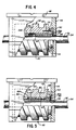
- a barrel-type drive cam is mounted (either directly or indirectly, as discussed below in relation to Figs. 4 and 5) by bearings 50 to the carriage housing walls 44, such that it is rotatable within the load carriage 40.
- the drive cam 48 comprises a constant lead-type barrel cam.
- an index cam, variable velocity cam, or an oscillating cam could be used for drive cam 48.
- the drive cam 48 is formed as a relatively short cam member. That is, in the preferred embodiment, the drive cam could be from 10 to 25 cm (four to ten inches) in length, for example, yet provide a linear stroke of several feet or more. This is contrasted to the prior art devices where the drive cam necessarily extended the entire length of the desired linear stroke. Thus, it was not uncommon for such prior devices' cams to be several meters (feet) or more in length.
- bearings 50 can be roller bearings, ball bearings, tapered roller bearings, or any other type bearing which gives proper rotational support on the carriage wall 44 to the drive cam 48.
- the drive cam 48 is rotatably driven by a ball slide mechanism, generally denoted by reference numeral 49, which mechanism also permits the cam 48 to move linearly along the cam's axis of rotation (which as seen in Fig. 1 is parallel to the aligned series of cam followers 38).
- a ball slide mechanism generally denoted by reference numeral 49
- the left end of ball spline shaft 52 is connected to and rotatably driven by the output (not shown) of the reducer 26.
- the ball spline shaft 52 is of the type having radially-protruding and longitudinally-extending drive ribs 54 (see Figs. 1 and 2).
- the other half of the ball slide mechanism comprises a flanged spline nut 56.
- the spline nut 56 comprises two separate halves 56A, 56B.
- the ball slide mechanism 49 is a commercially available ball spline shaft mechanism sold under the THK brand.
- the ball spline shaft 52 along with the flanged spline nuts 56A, 56B, extend through the central bore 58 of drive cam 48.
- the flanged spline nuts 56A, 56B are journalled directly by the bearings 50 and are fastened via threaded fasteners 60 and dowel pin 61 to the drive cam 48, such that rotation of the flanged spline nut 56 effects rotation of the drive cam 48 and vice versa.
- the recirculating drive balls 62 of the ball slide mechanism 49 are retained by a retainer ring 64 on the interior of the spline nut 56. So as to prevent unwanted backlash for actuator 20, the drive balls 62 are pre-loaded during assembly against the respective drive ribs 54 of ball spline shaft 52. Also it will be understood that other configurations for the ball slide mechanism 49 will work in the present invention, as long as both rotary motion and linear sliding movement is provided by the particular mechanism's slide member to the drive cam 48.
- each of the cam roller followers 38 comprises a threaded stud portion 66 which extends through an appropriate opening 68 of the track support 36.
- the threaded stud 66 terminates at one end in an enlarged head portion 70 against which is seated the cam roller 72 and the needle bearings 74; these are retained by a retainer ring 76.
- the other end of the stud 66 is retained against the track support 36 by a fastener 78.
- the cam followers 38 thus, provide high load-carrying capacity for the linear slide actuator 20. Also, so as to prevent unwanted backlash during operation, the drive cam is pre-loaded as is well-known against the cam followers 38 during assembly of the linear actuator 20.
- Each of the aligned and equally-spaced cam roller followers 38 is able to engage the respective convolutions of helical cam lobe 80 of the rotating drive cam 48.
- the spacing between the centerlines of the followers 38 is equal to the pitch dimension of the helical cam lobe 80
- the followers 38 are each positionally affixed to track support 36 and thus, do not move relative to the slidable load carriage assembly 40. That is, the cam 48 moves along the line of roller followers 38, not vice versa.
- Figure 5 depicts an alternate arrangement for attaching the slide member of the ball slide mechanism 49 to the drive cam 48. That is, rather than using a flanged spline nut 56 (see Fig. 4), Fig. 5 depicts a modified spline nut 82 comprising respective spline nut halves 82A, 82B, which are separated by a spacer 84.
- the spline nut halves 82A, 82B are respectively secured to the drive cam 48 by retainer keys 88 fitted in mating keyways (see keyway 89 in Fig. 2).
- the recirculating drive balls 62 are retained to the spline nut halves 82A, 82B by retainer rings 86.
- the spline nut halves 82A, 82B are retained axially relative to the drive cam 48 by an end retainer plate 90 (only one shown).
- the motor 22 and reducer 26 operate to drivably rotate the ball spline shaft 52 in either direction, and for a specific number or degrees of rotation(s).
- the motor 22 can be a so-called stepping motor, whereupon by selectively turning on and off the motor 22 for desired periods via control means (not shown), a known rotation for ball spline shaft 52 can be achieved.
- a stepping motor would be combined with a drive cam 48 of the so-called lead-cam or constant velocity design.
- Another motor usable with such cams is a so-called servo motor.
- the drive cam 48 could be an indexing-type cam, of a barrel cam design.
- the motor 22 preferably would be a constant rotation type motor. This specific combination would result in a step-wise movement, i.e., a fixed incremental indexing movement, for the ball spline shaft 52.
- Yet another type motor 22 that could be used with the present invention is an alternating current type motor, with an accompanying clutch brake.
- any rotation thereof will likewise cause the associated spline nut 56 to rotate, due to the angularly-constrained recirculating drive balls 62.
- the drive cam 48 is affixed by fasteners 60 (or alternatively by keys 88) to the spline nut 56 (or alternatively the nut 82), the drive cam 48 also is caused to rotate.
- any rotation of the cam 48 causes it to be linearly moved. That is, rotation of cam 48 causes the engaged roller followers 38 to create a linear thrust motion on the cam lobes 80, whereby the drive cam 48 (and the affixed spline nut 56 or 82) is caused to be linearly driven along the ball spline shaft 52.
- any linear movement induced into drive cam 48 necessarily causes the load carriage assembly 40 to also move linearly, as journalled along the guide tracks 34A, 34B.
- controlled rotary positioning of the ball spline shaft 52 effects the desired linear positioning of the load carriage assembly 40.
- any number of different linear actuation motions can be achieved for the load carriage assembly 40 and any tooling or workpiece gripper devices associated therewith.
- the present invention permits the use of a relatively short drive cam member 48, several significant advantages are achieved.
- Second, the cam's short length permits it to be easily moved out of the way when a particular cam roller follower element 38 becomes worn and needs replacement, i.e., easy accessibility.
- Third, the cam's short length inherently results in relatively low moments of inertia as seen by the reducer 26 and drive motor 22, thereby permitting use of small capacity motor drive assembly components, yet without compromising the ultimate output load capability of the linear actuator.
- Fourth, the drive cam 48 need not be custom built for each different required slide movement.
- one drive cam 48 (and the associated load carriage assembly 40) can work for many different lengths of required linear stroke, and only the length of the aligned series of cam followers need be changed in any given application. And fifth, since the cam 48 is relatively short and only a given number of followers 38 are engaged with the cam at any one time, the longevity of the followers 38 is greatly enhanced.
Landscapes
- Engineering & Computer Science (AREA)
- General Engineering & Computer Science (AREA)
- Mechanical Engineering (AREA)
- Transmission Devices (AREA)
- Press Drives And Press Lines (AREA)
Claims (4)
- Actionneur linéaire comprenant un ensemble moteur d'entraînement, un organe d'entraînement formant came (48) accouplé opérationnellement à l'ensemble moteur d'entraînement de manière à être entraîné par ce dernier et pourvu d'un lobe hélicoïdal formant came (80) présentant une pluralité de spires, une pluralité d'organes suiveurs de came alignés (38) dont chacun est maintenu en position fixe et peut être respectivement en prise avec l'organe d'entraînement formant came (48), et un chariot de charge (40) monté mobile à coulissement sur un ensemble de piste allongé (28), le long d'un trajet parallèle à la pluralité d'organes suiveurs de came alignés (38), ce chariot de charge étant supporté à rotation par rapport à l'organe d'entraînement (48) formant came, de telle façon que la rotation de l'ensemble moteur d'entraînement provoque la rotation de l'organe d'entraînement formant came (48) et que l'engagement des organes suiveurs de came (38), à position fixe, dans l'organe d'entraînement formant came (48) amène l'organe d'entraînement formant came (48) et le chariot de charge (40) à se déplacer linéairement, caractérisé en ce qu'il comprend un mécanisme de coulissement (49) entraîné par l'ensemble moteur d'entraînement, ce mécanisme de coulissement (49) comprenant un arbre allongé (52) dont les extrémités sont supportées à rotation dans l'ensemble de piste allongé (28), et un moyen coulissant disposé autour de cet arbre allongé (52), étant entraîné en rotation par cet arbre et pouvant coulisser axialement sur celui-ci, l'ensemble moteur d'entraînement étant monté fixe à une extrémité de l'ensemble de piste allongé (28) et ayant son organe de sortie accouplé directement à l'arbre allongé (52) pour l'entraîner en rotation, l'organe d'entraînement formant came (48) étant monté fixe sur le moyen coulissant afin de tourner et de coulisser linéairement conjointement avec ce dernier, l'organe d'entraînement formant came (48) étant précontraint contre les organes suiveurs de came (38), de manière à empêcher un jeu entre eux, les organes suiveurs de came alignés (38) étant équidistants les uns des autres, l'espacement entre les axes des organes suiveurs de came (38) étant égal à la dimension du pas du lobe hélicoïdal (80) formant came.
- Actionneur linéaire suivant la revendication 1 caractérise en ce que l'arbre d'entraînement (52) présente des nervures d'entraînement (54) faisant saillie radialement et le moyen coulissant est constitué par un écrou cannelé coulissant à billes (56,82) portant une série de billes d'entraînement (62) remises en circulation, pouvant venir en prise avec les nervures d'entraînement (54).
- Actionneur linéaire suivant la revendication 2 caractérisé en ce que les nervures d'entraînement (54) s'étendent dans le sens longitudinal de l'arbre d'entraînement allongé (52).
- Actionneur linéaire suivant la revendication 1 caractérisé en ce que le chariot de charge (40) est monté directement à rotation sur l'organe d'entraînement formant came (48).
Applications Claiming Priority (2)
| Application Number | Priority Date | Filing Date | Title |
|---|---|---|---|
| US07/262,955 US4898044A (en) | 1988-10-26 | 1988-10-26 | Cam-driven linear actuator apparatus |
| US262955 | 1988-10-26 |
Publications (3)
| Publication Number | Publication Date |
|---|---|
| EP0366594A2 EP0366594A2 (fr) | 1990-05-02 |
| EP0366594A3 EP0366594A3 (en) | 1990-06-20 |
| EP0366594B1 true EP0366594B1 (fr) | 1993-11-03 |
Family
ID=22999784
Family Applications (1)
| Application Number | Title | Priority Date | Filing Date |
|---|---|---|---|
| EP89630128A Expired - Lifetime EP0366594B1 (fr) | 1988-10-26 | 1989-08-02 | Actionneur linéaire à came |
Country Status (5)
| Country | Link |
|---|---|
| US (1) | US4898044A (fr) |
| EP (1) | EP0366594B1 (fr) |
| JP (1) | JPH02129449A (fr) |
| CA (1) | CA1313062C (fr) |
| DE (1) | DE68910468T2 (fr) |
Families Citing this family (19)
| Publication number | Priority date | Publication date | Assignee | Title |
|---|---|---|---|---|
| DE8912348U1 (de) * | 1989-10-18 | 1989-12-07 | Expert Maschinenbau Gmbh, 6143 Lorsch | Schrittantriebsvorrichtung |
| US5506377A (en) * | 1993-10-12 | 1996-04-09 | Emerson Electric Co. | Limit switch carrier assembly |
| JP4538212B2 (ja) * | 2002-10-24 | 2010-09-08 | 株式会社三共製作所 | 駆動機構およびこれを用いた移動テーブル |
| KR100629799B1 (ko) * | 2004-12-01 | 2006-09-28 | 현대모비스 주식회사 | 모터를 이용한 액티브롤콘트롤 시스템 |
| PL2226152T3 (pl) * | 2009-03-02 | 2013-04-30 | Willcox Invest S A | Urządzenie do precyzyjnej manipulacji przedmiotami, takie jak urządzenie typu podnieś i umieść |
| US9856111B1 (en) * | 2009-04-24 | 2018-01-02 | Paul Anderson | Elevator structure and brake system therefor |
| US10435273B1 (en) * | 2009-04-24 | 2019-10-08 | Federal Equipment Company | Elevator structure and brake system therefor |
| US9457988B1 (en) | 2009-04-24 | 2016-10-04 | Federal Equipment Company | Elevator structure and brake system therefor |
| US8347935B2 (en) * | 2010-02-12 | 2013-01-08 | Alexander Svirsky | Rigid retractable patio or window awning and operating mechanisms therefor |
| JP5901052B2 (ja) * | 2011-10-03 | 2016-04-06 | テクノダイナミックス株式会社 | カム装置 |
| US8925407B1 (en) * | 2011-11-30 | 2015-01-06 | Roger Henry Siminoff | Adjustable pressure assembly for a rotating plate in an automotive steering box |
| ITVR20120033A1 (it) * | 2012-02-28 | 2013-08-29 | Horvath Ildiko | Accoppiamento vite madrevite |
| CN102734415A (zh) * | 2012-07-02 | 2012-10-17 | 杭州赛奇高空作业机械有限公司 | 多用途螺杆与滚轮耦合传动装置 |
| CN102990966B (zh) * | 2012-12-26 | 2015-07-22 | 宣化冶金工业有限责任公司 | 双头机械式压棒机 |
| CN106808288A (zh) * | 2015-11-30 | 2017-06-09 | 湖南衡泰机械科技有限公司 | 一种数控雕铣加工平台 |
| DE102017116414A1 (de) | 2017-07-20 | 2019-01-24 | Weiss Gmbh | Transportvorrichtung zur rotatorischen und/oder linearen bewegung eines werkstücks |
| WO2019112556A1 (fr) | 2017-12-05 | 2019-06-13 | Flowserve Management Company | Capteurs de position de systèmes de dispositif obturateur, et ensembles, systèmes et procédés associés |
| CN108547923B (zh) * | 2018-06-06 | 2021-05-18 | 上海厚昌精密机械有限公司 | 一种可无限延长的高精度直线位移传动机构 |
| DE102021128917B3 (de) | 2021-11-05 | 2022-08-25 | Markus Schaack | Schaltwalze |
Family Cites Families (19)
| Publication number | Priority date | Publication date | Assignee | Title |
|---|---|---|---|---|
| US327048A (en) * | 1885-09-29 | Safety attachment for elevators and inclined railways | ||
| US647491A (en) * | 1899-06-14 | 1900-04-17 | Ernst Gustav Hoffmann | Worm-gearing. |
| US755416A (en) * | 1900-03-12 | 1904-03-22 | Charles Tuckfield | Mechanism for converting reciprocating into rotary motion, and vice versa. |
| FR412397A (fr) * | 1910-02-08 | 1910-07-11 | Gabriel Sylvain Danial | Baladeur produisant la révolution et la translation des travailleurs, pour pétrins rectangulaires fixes |
| US1294125A (en) * | 1917-09-19 | 1919-02-11 | Daniel F Lepley | Machine element. |
| US1500099A (en) * | 1922-08-31 | 1924-07-08 | Miner Inc W H | Hand brake |
| US3469460A (en) * | 1964-11-24 | 1969-09-30 | Georges Mersch | Phase displacement device of two shafts |
| FR2126825A5 (fr) * | 1971-02-13 | 1972-10-06 | Schiess Ag | |
| US3720115A (en) * | 1971-02-16 | 1973-03-13 | T Vertin | Machine element drive means |
| US3798984A (en) * | 1972-08-22 | 1974-03-26 | Joyce Bros Pty Ltd W A | Rotary clothes hoists |
| GB1477821A (en) * | 1975-04-16 | 1977-06-29 | Rino Berardi Spa Off Mec | Device for controlling the relative motions of two structural members or components particularly in machine tools |
| US4285249A (en) * | 1979-02-19 | 1981-08-25 | Kabushiki Kaisha I.T.L. | Apparatus for causing axial movement |
| US4438986A (en) * | 1981-03-13 | 1984-03-27 | Hiroshi Teramachi | Ball screw assembly containing a ball spline unit for exact slow feed and power transmission mechanism comprising said ball screw assembly |
| JPS58217849A (ja) * | 1982-06-12 | 1983-12-17 | Kazuo Fujita | ロ−ラスクリユウ |
| FR2535426A1 (fr) * | 1982-11-02 | 1984-05-04 | Gouache Ind | Dispositif de deplacement avec precision d'un organe le long d'une trajectoire |
| DE3507497C1 (de) * | 1985-03-02 | 1986-07-31 | PROMA Produkt- und Marketing-Gesellschaft mbH, 7310 Plochingen | Mechanische Linearantriebseinheit |
| US4715774A (en) * | 1985-12-23 | 1987-12-29 | Peddinghaus Corporation | Workpiece advancing apparatus |
| US4765651A (en) * | 1986-05-13 | 1988-08-23 | American Safety Equipment Corporation | Adjustable anchoring slide block assembly |
| JPH0684776B2 (ja) * | 1987-03-18 | 1994-10-26 | 博 寺町 | 複合運動案内ユニットおよびこれを用いた複合運動案内装置 |
-
1988
- 1988-10-26 US US07/262,955 patent/US4898044A/en not_active Expired - Fee Related
-
1989
- 1989-07-20 CA CA000606219A patent/CA1313062C/fr not_active Expired - Fee Related
- 1989-08-02 EP EP89630128A patent/EP0366594B1/fr not_active Expired - Lifetime
- 1989-08-02 DE DE89630128T patent/DE68910468T2/de not_active Expired - Fee Related
- 1989-08-30 JP JP1224316A patent/JPH02129449A/ja active Pending
Also Published As
| Publication number | Publication date |
|---|---|
| DE68910468T2 (de) | 1994-03-03 |
| DE68910468D1 (de) | 1993-12-09 |
| EP0366594A3 (en) | 1990-06-20 |
| US4898044A (en) | 1990-02-06 |
| CA1313062C (fr) | 1993-01-26 |
| JPH02129449A (ja) | 1990-05-17 |
| EP0366594A2 (fr) | 1990-05-02 |
Similar Documents
| Publication | Publication Date | Title |
|---|---|---|
| EP0366594B1 (fr) | Actionneur linéaire à came | |
| US3803927A (en) | Coaxial force and movement mechanism for a machine tool | |
| FI74788C (fi) | Lineaerdrivanordning, foersedd med tvao motorer. | |
| KR920007779B1 (ko) | 복합 운동 안내 유닛 및 그를 사용한 복합 운동 안내장치 | |
| KR100363691B1 (ko) | 회전방지장치 및 회전방지 기능을 구비한 전동액추에이터 | |
| DE60028876T2 (de) | Automatiktüranordnung und automatischer türbetätiger dafür | |
| US4557156A (en) | Rotary-to-linear converter with rolling balls, and feed mechanisms incorporating the same | |
| DE4412403C2 (de) | Elektrische Verstellvorrichtung | |
| US5094118A (en) | Splined ball screw assembly having a nested structure | |
| CA2116879C (fr) | Ecrou a roulement a rouleaux our actionneur lineaire a vis sans fin | |
| CN1033020A (zh) | 带行星传动与定位装置的刀架转台 | |
| EP0482827B1 (fr) | Mécanisme convertissant un mouvement rotatif en un mouvement rectiligne | |
| DE3521055A1 (de) | Zufuehrvorrichtung mit einer kugelumlaufspindel | |
| DE3207163C2 (de) | Kraftübertragungsmechanismus | |
| JPH02138547A (ja) | ボールねじ | |
| US4872362A (en) | Driving mechanism and manipulator comprising such a driving mechanism | |
| EP0489115A4 (en) | Improved screw and nut machine | |
| EP0191777A1 (fr) | Dispositif d'entrainement lineaire. | |
| US4897588A (en) | Double motor feed control system | |
| US5303604A (en) | Feed system | |
| US6327925B1 (en) | Linear drive unit | |
| DE4102083A1 (de) | Steuer- bzw. antriebssystem | |
| JP2001021019A (ja) | ボールねじおよび駆動装置 | |
| GB2059540A (en) | Apparatus for Producing Axial Movement | |
| JP7555488B2 (ja) | 電動式直動装置 |
Legal Events
| Date | Code | Title | Description |
|---|---|---|---|
| PUAI | Public reference made under article 153(3) epc to a published international application that has entered the european phase |
Free format text: ORIGINAL CODE: 0009012 |
|
| AK | Designated contracting states |
Kind code of ref document: A2 Designated state(s): BE CH DE FR GB IT LI NL |
|
| PUAL | Search report despatched |
Free format text: ORIGINAL CODE: 0009013 |
|
| AK | Designated contracting states |
Kind code of ref document: A3 Designated state(s): BE CH DE FR GB IT LI NL |
|
| 17P | Request for examination filed |
Effective date: 19901030 |
|
| 17Q | First examination report despatched |
Effective date: 19911202 |
|
| GRAA | (expected) grant |
Free format text: ORIGINAL CODE: 0009210 |
|
| AK | Designated contracting states |
Kind code of ref document: B1 Designated state(s): BE CH DE FR GB IT LI NL |
|
| PG25 | Lapsed in a contracting state [announced via postgrant information from national office to epo] |
Ref country code: IT Free format text: LAPSE BECAUSE OF FAILURE TO SUBMIT A TRANSLATION OF THE DESCRIPTION OR TO PAY THE FEE WITHIN THE PRE;WARNING: LAPSES OF ITALIAN PATENTS WITH EFFECTIVE DATE BEFORE 2007 MAY HAVE OCCURRED AT ANY TIME BEFORE 2007. THE CORRECT EFFECTIVE DATE MAY BE DIFFERENT FROM THE ONE RECORDED.SCRIBED TIME-LIMIT Effective date: 19931103 Ref country code: CH Effective date: 19931103 Ref country code: BE Effective date: 19931103 Ref country code: LI Effective date: 19931103 Ref country code: NL Effective date: 19931103 Ref country code: FR Effective date: 19931103 |
|
| REF | Corresponds to: |
Ref document number: 68910468 Country of ref document: DE Date of ref document: 19931209 |
|
| REG | Reference to a national code |
Ref country code: CH Ref legal event code: PL |
|
| EN | Fr: translation not filed | ||
| NLV1 | Nl: lapsed or annulled due to failure to fulfill the requirements of art. 29p and 29m of the patents act | ||
| PG25 | Lapsed in a contracting state [announced via postgrant information from national office to epo] |
Ref country code: GB Effective date: 19940802 |
|
| PLBE | No opposition filed within time limit |
Free format text: ORIGINAL CODE: 0009261 |
|
| STAA | Information on the status of an ep patent application or granted ep patent |
Free format text: STATUS: NO OPPOSITION FILED WITHIN TIME LIMIT |
|
| 26N | No opposition filed | ||
| GBPC | Gb: european patent ceased through non-payment of renewal fee |
Effective date: 19940802 |
|
| PG25 | Lapsed in a contracting state [announced via postgrant information from national office to epo] |
Ref country code: DE Effective date: 19950503 |