EP0366507B1 - Elektrisches Gerät mit verbessertem Batteriefach - Google Patents
Elektrisches Gerät mit verbessertem Batteriefach Download PDFInfo
- Publication number
- EP0366507B1 EP0366507B1 EP89402604A EP89402604A EP0366507B1 EP 0366507 B1 EP0366507 B1 EP 0366507B1 EP 89402604 A EP89402604 A EP 89402604A EP 89402604 A EP89402604 A EP 89402604A EP 0366507 B1 EP0366507 B1 EP 0366507B1
- Authority
- EP
- European Patent Office
- Prior art keywords
- electrical
- housing
- compartment
- face
- measuring appliance
- Prior art date
- Legal status (The legal status is an assumption and is not a legal conclusion. Google has not performed a legal analysis and makes no representation as to the accuracy of the status listed.)
- Expired - Lifetime
Links
Images


Classifications
-
- H—ELECTRICITY
- H05—ELECTRIC TECHNIQUES NOT OTHERWISE PROVIDED FOR
- H05K—PRINTED CIRCUITS; CASINGS OR CONSTRUCTIONAL DETAILS OF ELECTRIC APPARATUS; MANUFACTURE OF ASSEMBLAGES OF ELECTRICAL COMPONENTS
- H05K5/00—Casings, cabinets or drawers for electric apparatus
- H05K5/0086—Casings, cabinets or drawers for electric apparatus portable, e.g. battery operated apparatus
-
- G—PHYSICS
- G01—MEASURING; TESTING
- G01R—MEASURING ELECTRIC VARIABLES; MEASURING MAGNETIC VARIABLES
- G01R1/00—Details of instruments or arrangements of the types included in groups G01R5/00 - G01R13/00 and G01R31/00
- G01R1/02—General constructional details
- G01R1/04—Housings; Supporting members; Arrangements of terminals
Definitions
- the present invention relates to an electrical measuring device of the type comprising a box, one functional face of which combines the control and use members, and a voltage source comprising at least one electric battery disposed inside a compartment. of the housing which is accessed through an opening closed by a removable cover.
- the battery compartment can also receive device protection fuses.
- This design makes it possible to have the entire surface of the main printed circuit board which can extend into the bottom of the device and thus have a contour substantially complementary to that of the part constituting the bottom half-housing of the device.
- the electrical device is an electrical measuring device
- the arrangement of the battery compartment on the upper functional face of the housing must also make it possible to add great safety in the use of the device.
- the invention provides an electrical measuring device characterized in that the device is of the type comprising on its functional face a series of female electrical connection plugs allowing the connection of an electrical wire whose end is equipped with an additional male plug, and in that the removable cover comprises a series of orifices arranged opposite the series of female plugs, so as to allow the passage of the electrical contact element of the male plug for its introduction into the female plug and to prevent dismantling of the cover when the male plug is in the inserted position.
- the removable cover includes indications for locating the position of a control switch for the device.
- This characteristic further improves the safety of the measuring device in the event that the user reconnects the electrical measuring cords without replacing the removable cover, it would then be impossible for him to use the measuring device. since it could not position the control switch in the absence of the indications necessary for its use.
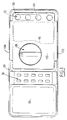
- the electrical measuring device shown in Figures 1 to 7 is a conventional device whose generally rectangular parallelepiped shape is made of two half-housings 20 and 22 between which there is a recess 24 marking the joint plane.
- FIG. 1 there is also shown a locking device 34 which makes it possible to retain the electrical connection plugs inserted in the measuring device in accordance with the characteristics of patent application FR-A-2,587,849, the content of which we can advantageously refer.
- the locking device 34 is not shown in FIG. 1.
- the apparatus comprises a main electronic circuit which is mounted on a main rectangular printed circuit plate 36 as well as on a secondary plate 39 which are arranged inside the internal cavity 38 of the housing.
- the main electronic components and switching circuits the device is not shown in the figures.
- the main printed circuit board 36 has a rectangular contour substantially equal to that of the two half-housings and thus has a maximum surface for the production of the circuits of the device.
- the upper half-housing 20 On its functional upper face which groups the control and use members 26, 28, 30 and 32, the upper half-housing 20 has an opening 44 opening upwards to allow access to a compartment 46 in which an electric battery 47 and protective fuses 48 and 50 are arranged.
- the tightness of the battery compartment 46, with respect to the outside, is ensured by means of a full continuous and flexible membrane 90.
- the membrane 90 extends in a plane and defines a substantially rectangular external contour which corresponds to the contour of the opening 44 for access to the battery compartment 46.
- the contour 44 is delimited by a continuous groove 92 in which is received a seal of circular section 94 made integrally with the membrane 90.
- the latter is provided with a gripping tab 106 made integrally with the membrane 90 and which is received, when it is in place, in a hollow housing 108 formed in the upper face of the upper half-housing 20.
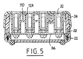
- a cover made of rigid material 110 which covers the membrane 90 and which is fixed to the upper half-case 20 by the ends 112 and 114 on its two sides which are fitted onto the body of the upper half-casing 20.
- the removable cover 110 has an end portion 120 which extends beyond the contour 44 of the cavity 46 to extend, when in position on the upper half-housing 20, to the above the sockets 32 which allow the connection of male plugs of the type of plug 122 shown diagrammatically in FIG. 7.
- This part 120 of the cover 110 comprises a series of four openings 124 which allow the connection of the test lead 127 fitted to the male plug 122 in the socket 32 arranged opposite the orifice 124.
- the four holes 124 are of course arranged symmetrically opposite four sockets 32 to allow connection in different measurement positions.
- the removable cover 110 also includes indications 126 allowing the user to identify the position of the button 128 of the control switch 28 in order to choose the range of use of the measuring device.
- the button 28 passes through the removable cover 110 by a circular recess 130 formed in the latter.
- the battery compartment 46 is delimited by a side wall 132 whose profile corresponds to that of the contour of the groove 92 and by a bottom wall 134, these two walls 132 and 134 having come integrally with the monobloc piece constituting the half upper case 20.
- the bottom wall 134 has openings 136 and 138 allowing in particular the passage of the members electrical connection 140 and 142 of fuses 48 and 50, as well as two openings 144 allowing the passage of connection terminals 145 for the electrical connection of battery 47.
- a foam sealing membrane 146 is provided, which is disposed between the lower face of the bottom 134 and the upper face of the main circuit plate. printed 36.
- the foam sealing membrane 146 has slots which allow the connection members 140, 142 and the terminals 145 for connection to the battery 47 to pass through it in a sealed manner.
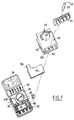
- the user begins by disconnecting the male plugs 122 which are possibly in place in the sockets 32 and which pass through the safety device 34, if the measuring device is equipped with such a device, and the orifices 124 of the removable cover 110 .
- the latter comprises, since its opening of introduction 150, two successive cutouts 152 and 154 which allow the introduction of '' a fuse 48 with a diameter corresponding to that of the circular opening 152 or that of the circular opening 154.
- This characteristic advantageously makes it possible to market the same device in countries having different standardizations as to the diameters and sizes of the fuses to be used, for example 8 x 32 mm or 6.3 x 32 mm fuses.
- the battery 47 is a 9 Volt parallelepiped battery known under the standard reference 6LF22.
- the housing of the measuring device which has just been described with the arrangement of the battery compartment accessible from the functional control and use face is such that, in normal use and maintenance, the user has not never open the main housing and only needs to access compartment 46 in which are arranged battery 47 and fuses 48 and 50.
- the lower half-housing 22 is equipped with a stand 200 which is articulated around an axis 202 to allow the device to be used in an inclined position, for example relative to a plane of horizontal work.
- the free end 204 of the stand is bevelled so as to have a reduced thickness similar to that of the tip of a screwdriver.
- the stand which is easily removable, can thus be detached from the housing of the device to form a disassembly tool.
- the user can in fact advantageously use the beveled end 204 by introducing it into the joint plane 24, under the ends 112 and 114 of the cover 110.
- the stand 200 being made of the same thermoplastic material as the housings and the covers, it constitutes a non-aggressive tool for these elements, which prevents their accidental deterioration.
Landscapes
- Engineering & Computer Science (AREA)
- Microelectronics & Electronic Packaging (AREA)
- Physics & Mathematics (AREA)
- General Physics & Mathematics (AREA)
- Battery Mounting, Suspending (AREA)
- Connection Of Batteries Or Terminals (AREA)
Claims (8)
- Elektrisches Meßgerät, mit einem Gehäuse (20), dessen Bedienfläche Steuerungs- und Bedienungseinrichtungen (26,28,30,32) umfaßt, und mit einer Spannungsquelle, die mindestens eine Batterie (47) aufweist, die im Inneren eines Fachs (46) des Gehäuses (20) angeordnet ist, welches über eine in der Bedienfläche ausgebildete Öffnung (44) zugänglich und mit einer lösbaren Abdeckung (110) verschlossen ist, dadurch gekennzeichnet, daß das Meßgerät auf seiner Bedienfläche eine Reihe von Steckerbuchsen (32) zur elektrischen Verbindung aufweist, welche den Anschluß eines Leitungsdrahts (127) ermöglichen, dessen Ende mit einem komplementären Stecker (122) versehen ist, und daß die lösbare Abdeckung (110) eine Reihe von Öffnungen (124) aufweist, die der Reihe von Steckerbuchsen (32) gegenüberliegend angeordnet sind, so daß der Durchtritt des elektrischen Kontaktelements des Steckers beim Einstecken in die Steckerbuchse möglich und die das Entfernen der lösbaren Abdeckung (110) nicht möglich ist, wenn der Stecker eingesteckt ist.
- Elektrisches Meßgerät nach Anspruch 1, dadurch gekennzeichnet, daß die lösbare Abdeckung (110) Markierungen (126) aufweist, anhand derer die Position eines Schalters (28) zur Steuerung des Meßgeräts bestimmbar ist.
- Elektrisches Meßgerät nach Anspruch 2, dadurch gekennzeichnet, daß der Schulter (28) mit einem Steuerknopf (128) versehen ist, der in einem Ausschnitt (130) des lösbaren Abdeckung (110) bewegbar ist.
- Elektrisches Meßgerät nach einem der vorhergehenden Ansprüche, dadurch gekennzeichnet, daß das Fach (46) von einer Längswand (132) und einer Bodenfläche (134) umschlossen ist, wobei letztere von Mitteln (140,142,145) zur elektrischen Verbindung der Spannungsquelle mit einer im Innenraum (38) des Gehäuses (20) angeordneten elektrischen Schaltung durchdrungen ist.
- Elektrisches Meßgerät nach Anspruch 4, dadurch gekennzeichnet, daß die Abdichtung des Fachs (46) gegenüber dem Innenraum (38) des Gehäuses (20) durch eine Abdichtmembran (146) gewährleistet ist, die zwischen der Innenseite der Bodenfläche (134) und einer im Innern des Gehäuses (20) befindlichen Stützfläche angeordnet ist, und daß diese Membran von den Mitteln zur elektrischen Verbindung durchdrungen ist.
- Elektrisches Meßgerät nach Anspruch 5, dadurch gekennzeichnet, daß die Stützfläche eine Fläche einer Platte (36) mit gedruckter Schaltung ist, die sich unter der Bodenfläche (134) des Fachs (46) erstreckt.
- Elektrisches Meßgerät nach einem der vorhergehenden Ansprüche, dadurch gekennzeichnet, daß im Fach (46) mindestens eine Sicherung (48,50) angebracht ist.
- Elektrisches Meßgerät nach einem der vorhergehenden Ansprüche, dadurch gekennzeichnet, daß die Öffnung (44) des Fachs (46) durch eine zwischen dem Gehäuse (20) und der lösbaren Abdeckung (110) angeordneten Abdichtmembran (90) verschlossen ist.
Applications Claiming Priority (2)
| Application Number | Priority Date | Filing Date | Title |
|---|---|---|---|
| FR8812602A FR2637153B1 (fr) | 1988-09-27 | 1988-09-27 | Appareil electrique a compartiment de pile perfectionne |
| FR8812602 | 1988-09-27 |
Publications (2)
| Publication Number | Publication Date |
|---|---|
| EP0366507A1 EP0366507A1 (de) | 1990-05-02 |
| EP0366507B1 true EP0366507B1 (de) | 1993-10-27 |
Family
ID=9370428
Family Applications (1)
| Application Number | Title | Priority Date | Filing Date |
|---|---|---|---|
| EP89402604A Expired - Lifetime EP0366507B1 (de) | 1988-09-27 | 1989-09-22 | Elektrisches Gerät mit verbessertem Batteriefach |
Country Status (4)
| Country | Link |
|---|---|
| US (1) | US5084670A (de) |
| EP (1) | EP0366507B1 (de) |
| DE (1) | DE68910269T2 (de) |
| FR (1) | FR2637153B1 (de) |
Cited By (1)
| Publication number | Priority date | Publication date | Assignee | Title |
|---|---|---|---|---|
| DE4438239C1 (de) * | 1994-10-26 | 1996-06-05 | Mueller & Weigert | Batteriebetriebenes Meßgerät, insbesondere Zangenanlegegerät |
Families Citing this family (12)
| Publication number | Priority date | Publication date | Assignee | Title |
|---|---|---|---|---|
| GB2259574B (en) * | 1991-09-12 | 1995-08-30 | Heme Int Ltd | Measuring devices |
| JPH07270457A (ja) * | 1994-04-01 | 1995-10-20 | Seiko Epson Corp | デジタルマルチメータ |
| US5834935A (en) * | 1997-03-18 | 1998-11-10 | Tektronix, Inc. | Hand held instrument with safety locked battery compartment |
| US5920188A (en) * | 1997-11-25 | 1999-07-06 | Fluke Corporation | Voltage measurement instrument having transient overvoltage input protection |
| US20030132863A1 (en) * | 2001-12-06 | 2003-07-17 | Lahr Roy J. | Articulated, rotatable expandable and contractible keyboard device |
| WO2003050953A2 (en) | 2001-12-06 | 2003-06-19 | Rast Associates, Llc | Expandable and contractible keyboard device |
| DE102005036037A1 (de) * | 2005-08-01 | 2007-02-08 | Robert Bosch Gmbh | Messgerät |
| US7830135B2 (en) * | 2007-08-14 | 2010-11-09 | Fluke Corporation | Digital multimeter having housing sealing arrangement |
| US7911200B2 (en) * | 2007-08-14 | 2011-03-22 | Fluke Corporation | Digital multimeter having case panel structure |
| US7654857B2 (en) * | 2007-08-14 | 2010-02-02 | Fluke Corporation | Digital multimeter having sealed input jack detection arrangement |
| DE202009012059U1 (de) * | 2009-09-07 | 2011-02-03 | Conrad Electronic Se | Messinstrument |
| USD890617S1 (en) * | 2019-01-22 | 2020-07-21 | Chauvin Arnoux | Ohmmeter |
Family Cites Families (16)
| Publication number | Priority date | Publication date | Assignee | Title |
|---|---|---|---|---|
| US1739142A (en) * | 1924-04-10 | 1929-12-10 | Thomas E Murray Jr | Switch-box cover and attachment |
| FR1533837A (fr) * | 1967-08-09 | 1968-07-19 | Eastman Kodak Co | Boîtier perfectionné, notamment pour appareil de prise de vues |
| US3763752A (en) * | 1972-04-14 | 1973-10-09 | Perfect Film & Chem Corp | Camera with built-in stroboscopic flash |
| US3881961A (en) * | 1973-08-02 | 1975-05-06 | Motorola Inc | Battery housing |
| US4317628A (en) * | 1979-08-06 | 1982-03-02 | Canon Kabushiki Kaisha | Electric circuit protection device for camera |
| US4297635A (en) * | 1979-11-19 | 1981-10-27 | General Electric Company | Watthour meter and battery retaining apparatus therefor |
| US4439736A (en) * | 1981-05-13 | 1984-03-27 | Cable Electric Products, Inc. | Battery testing system |
| EP0408401B1 (de) * | 1982-07-22 | 1995-03-22 | Texas Instruments Incorporated | Tastatur für einen elektronischen Apparat |
| DE3344311A1 (de) * | 1983-12-07 | 1985-06-20 | Ruhrkohle Ag, 4300 Essen | Messgeraet, insbesondere laufzeitmessgeraet zur ortung von kabelfehlern |
| JPS61120265A (ja) * | 1984-11-16 | 1986-06-07 | Canon Inc | 電子機器 |
| JPS61278830A (ja) * | 1985-06-04 | 1986-12-09 | Konishiroku Photo Ind Co Ltd | ストロボ内蔵カメラ |
| US4713609A (en) * | 1985-09-05 | 1987-12-15 | General Electric Company | Battery backup installation for electric meter |
| FR2587849B1 (fr) * | 1985-09-23 | 1989-11-10 | Itt Composants Instr | Dispositif de verrouillage de fiche pour appareil de mesure |
| US4752539A (en) * | 1986-11-10 | 1988-06-21 | Spectra-Physics, Inc. | Battery holder for electronic apparatus |
| US4847170A (en) * | 1988-09-09 | 1989-07-11 | Pulse Electronics, Inc. | Battery container and adapter |
| US4991058A (en) * | 1989-11-09 | 1991-02-05 | Grid Systems Corporation | Card housing attachment for a portable computer |
-
1988
- 1988-09-27 FR FR8812602A patent/FR2637153B1/fr not_active Expired - Fee Related
-
1989
- 1989-09-20 US US07/409,891 patent/US5084670A/en not_active Expired - Fee Related
- 1989-09-22 EP EP89402604A patent/EP0366507B1/de not_active Expired - Lifetime
- 1989-09-22 DE DE89402604T patent/DE68910269T2/de not_active Expired - Fee Related
Cited By (1)
| Publication number | Priority date | Publication date | Assignee | Title |
|---|---|---|---|---|
| DE4438239C1 (de) * | 1994-10-26 | 1996-06-05 | Mueller & Weigert | Batteriebetriebenes Meßgerät, insbesondere Zangenanlegegerät |
Also Published As
| Publication number | Publication date |
|---|---|
| DE68910269D1 (de) | 1993-12-02 |
| FR2637153B1 (fr) | 1993-03-26 |
| DE68910269T2 (de) | 1994-02-24 |
| FR2637153A1 (fr) | 1990-03-30 |
| US5084670A (en) | 1992-01-28 |
| EP0366507A1 (de) | 1990-05-02 |
Similar Documents
| Publication | Publication Date | Title |
|---|---|---|
| EP0366507B1 (de) | Elektrisches Gerät mit verbessertem Batteriefach | |
| EP2727192B1 (de) | Verwendung einer Steckdose und elektrische Einheit | |
| EP0987803B1 (de) | Schutzvorrichtung für elektrischen Anlagen gegen Speisungsstörungen | |
| EP0580505B1 (de) | Anpassungssystem zwischen einem Antennenstecker und der Buchse eines Funktelefons | |
| FR2777120A1 (fr) | Bague de reperage de la tension d'emploi d'un element de connexion electrique | |
| EP3840136B1 (de) | Mechanismus eines elektrischen geräts, entsprechende elektrische anordung und entsprechendes elektrisches gerät | |
| EP0093628B1 (de) | Steckdose mit mehreren Kontaktelementen | |
| FR2920256A1 (fr) | Socle de prise verrouille | |
| FR3045700B1 (fr) | Dispositif articule en rotation dote d’un systeme de connexion electrique | |
| EP3471124B1 (de) | Trennschalter der elektrischen versorgung für ein schutzmodul, und schutzmodul, das einen solchen trennschalter umfasst | |
| EP1033735B1 (de) | Elektronischer Auslöser mit einem abnehmbaren Langzeitverzögerungsmodul mit einer Ein- und Ausschaltungsfunktion | |
| EP0709685A1 (de) | Elektrischer Messapparat mit zugriffsgeschütztem Batteriefach | |
| FR2716756A1 (fr) | Ensemble perfectionné d'alimentation et de commande, pour un alternateur de véhicule automobile. | |
| EP3009812B2 (de) | Modular aufgebaute erfassungsvorrichtung, und diese umfassende industrieausrüstung | |
| EP1278224A1 (de) | Elektrische Verbindungsvorrichtung für zwei nebeneinander auf einer Schiene montierte elecktrische Geräte | |
| EP0418136A1 (de) | Hochspannungsanschlussvorrichtung für eine Zündspule, insbesondere für Brennkraftmaschinen von Kraftfahrzeugen | |
| EP3159906B1 (de) | Elektrische schaltvorrichtung mit einem schaltmechanismus und mindestens einem zusatzmodul | |
| FR2637152A1 (fr) | Boitier etanche, notamment pour un appareil electrique | |
| EP2843766B1 (de) | Elektrische Vorrichtung, die einen gedruckten elektrischen Schaltkreis auf einer Halterungsplatte und eine elektrische Anschlussklemme umfasst | |
| FR2490060A1 (fr) | Interrupteur de fin de course pouvant etre actionne sans contact | |
| FR3069715A1 (fr) | Bloc multi-appareillages avec element d'appui anti porte-a-faux | |
| EP0797271A1 (de) | Sockel für Stromsteckdose | |
| EP1825278A1 (de) | Elektrische verbindungseinrichtung für einen polyphasen-stromzähler | |
| CA2932321C (fr) | Dispositif de coupure electrique pour batterie d'accumulateurs | |
| FR2746231A1 (fr) | Carte electronique comportant une alimentation en energie electrique autonome sous forme d'au moins une pile |
Legal Events
| Date | Code | Title | Description |
|---|---|---|---|
| PUAI | Public reference made under article 153(3) epc to a published international application that has entered the european phase |
Free format text: ORIGINAL CODE: 0009012 |
|
| AK | Designated contracting states |
Kind code of ref document: A1 Designated state(s): DE FR GB IT NL |
|
| 17P | Request for examination filed |
Effective date: 19900728 |
|
| 17Q | First examination report despatched |
Effective date: 19910906 |
|
| GRAA | (expected) grant |
Free format text: ORIGINAL CODE: 0009210 |
|
| AK | Designated contracting states |
Kind code of ref document: B1 Designated state(s): DE FR GB IT NL |
|
| PG25 | Lapsed in a contracting state [announced via postgrant information from national office to epo] |
Ref country code: IT Free format text: LAPSE BECAUSE OF FAILURE TO SUBMIT A TRANSLATION OF THE DESCRIPTION OR TO PAY THE FEE WITHIN THE PRESCRIBED TIME-LIMIT;WARNING: LAPSES OF ITALIAN PATENTS WITH EFFECTIVE DATE BEFORE 2007 MAY HAVE OCCURRED AT ANY TIME BEFORE 2007. THE CORRECT EFFECTIVE DATE MAY BE DIFFERENT FROM THE ONE RECORDED. Effective date: 19931027 Ref country code: NL Effective date: 19931027 |
|
| REF | Corresponds to: |
Ref document number: 68910269 Country of ref document: DE Date of ref document: 19931202 |
|
| GBT | Gb: translation of ep patent filed (gb section 77(6)(a)/1977) |
Effective date: 19931108 |
|
| NLV1 | Nl: lapsed or annulled due to failure to fulfill the requirements of art. 29p and 29m of the patents act | ||
| PLBE | No opposition filed within time limit |
Free format text: ORIGINAL CODE: 0009261 |
|
| STAA | Information on the status of an ep patent application or granted ep patent |
Free format text: STATUS: NO OPPOSITION FILED WITHIN TIME LIMIT |
|
| 26N | No opposition filed | ||
| REG | Reference to a national code |
Ref country code: FR Ref legal event code: TP |
|
| REG | Reference to a national code |
Ref country code: GB Ref legal event code: 732E |
|
| REG | Reference to a national code |
Ref country code: FR Ref legal event code: TP |
|
| PGFP | Annual fee paid to national office [announced via postgrant information from national office to epo] |
Ref country code: FR Payment date: 20000831 Year of fee payment: 12 |
|
| PGFP | Annual fee paid to national office [announced via postgrant information from national office to epo] |
Ref country code: DE Payment date: 20000918 Year of fee payment: 12 |
|
| PGFP | Annual fee paid to national office [announced via postgrant information from national office to epo] |
Ref country code: GB Payment date: 20000920 Year of fee payment: 12 |
|
| REG | Reference to a national code |
Ref country code: GB Ref legal event code: 732E |
|
| PG25 | Lapsed in a contracting state [announced via postgrant information from national office to epo] |
Ref country code: GB Free format text: LAPSE BECAUSE OF NON-PAYMENT OF DUE FEES Effective date: 20010922 |
|
| REG | Reference to a national code |
Ref country code: GB Ref legal event code: IF02 |
|
| PG25 | Lapsed in a contracting state [announced via postgrant information from national office to epo] |
Ref country code: DE Free format text: LAPSE BECAUSE OF NON-PAYMENT OF DUE FEES Effective date: 20020501 |
|
| GBPC | Gb: european patent ceased through non-payment of renewal fee |
Effective date: 20010922 |
|
| PG25 | Lapsed in a contracting state [announced via postgrant information from national office to epo] |
Ref country code: FR Free format text: LAPSE BECAUSE OF NON-PAYMENT OF DUE FEES Effective date: 20020531 |
|
| REG | Reference to a national code |
Ref country code: FR Ref legal event code: ST |