EP0366507B1 - Electrical apparatus with improved cell compartment - Google Patents
Electrical apparatus with improved cell compartment Download PDFInfo
- Publication number
- EP0366507B1 EP0366507B1 EP89402604A EP89402604A EP0366507B1 EP 0366507 B1 EP0366507 B1 EP 0366507B1 EP 89402604 A EP89402604 A EP 89402604A EP 89402604 A EP89402604 A EP 89402604A EP 0366507 B1 EP0366507 B1 EP 0366507B1
- Authority
- EP
- European Patent Office
- Prior art keywords
- electrical
- housing
- compartment
- face
- measuring appliance
- Prior art date
- Legal status (The legal status is an assumption and is not a legal conclusion. Google has not performed a legal analysis and makes no representation as to the accuracy of the status listed.)
- Expired - Lifetime
Links
Images


Classifications
-
- H—ELECTRICITY
- H05—ELECTRIC TECHNIQUES NOT OTHERWISE PROVIDED FOR
- H05K—PRINTED CIRCUITS; CASINGS OR CONSTRUCTIONAL DETAILS OF ELECTRIC APPARATUS; MANUFACTURE OF ASSEMBLAGES OF ELECTRICAL COMPONENTS
- H05K5/00—Casings, cabinets or drawers for electric apparatus
- H05K5/0086—Casings, cabinets or drawers for electric apparatus portable, e.g. battery operated apparatus
-
- G—PHYSICS
- G01—MEASURING; TESTING
- G01R—MEASURING ELECTRIC VARIABLES; MEASURING MAGNETIC VARIABLES
- G01R1/00—Details of instruments or arrangements of the types included in groups G01R5/00 - G01R13/00 and G01R31/00
- G01R1/02—General constructional details
- G01R1/04—Housings; Supporting members; Arrangements of terminals
Definitions
- the present invention relates to an electrical measuring device of the type comprising a box, one functional face of which combines the control and use members, and a voltage source comprising at least one electric battery disposed inside a compartment. of the housing which is accessed through an opening closed by a removable cover.
- the battery compartment can also receive device protection fuses.
- This design makes it possible to have the entire surface of the main printed circuit board which can extend into the bottom of the device and thus have a contour substantially complementary to that of the part constituting the bottom half-housing of the device.
- the electrical device is an electrical measuring device
- the arrangement of the battery compartment on the upper functional face of the housing must also make it possible to add great safety in the use of the device.
- the invention provides an electrical measuring device characterized in that the device is of the type comprising on its functional face a series of female electrical connection plugs allowing the connection of an electrical wire whose end is equipped with an additional male plug, and in that the removable cover comprises a series of orifices arranged opposite the series of female plugs, so as to allow the passage of the electrical contact element of the male plug for its introduction into the female plug and to prevent dismantling of the cover when the male plug is in the inserted position.
- the removable cover includes indications for locating the position of a control switch for the device.
- This characteristic further improves the safety of the measuring device in the event that the user reconnects the electrical measuring cords without replacing the removable cover, it would then be impossible for him to use the measuring device. since it could not position the control switch in the absence of the indications necessary for its use.
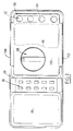
- the electrical measuring device shown in Figures 1 to 7 is a conventional device whose generally rectangular parallelepiped shape is made of two half-housings 20 and 22 between which there is a recess 24 marking the joint plane.
- FIG. 1 there is also shown a locking device 34 which makes it possible to retain the electrical connection plugs inserted in the measuring device in accordance with the characteristics of patent application FR-A-2,587,849, the content of which we can advantageously refer.
- the locking device 34 is not shown in FIG. 1.
- the apparatus comprises a main electronic circuit which is mounted on a main rectangular printed circuit plate 36 as well as on a secondary plate 39 which are arranged inside the internal cavity 38 of the housing.
- the main electronic components and switching circuits the device is not shown in the figures.
- the main printed circuit board 36 has a rectangular contour substantially equal to that of the two half-housings and thus has a maximum surface for the production of the circuits of the device.
- the upper half-housing 20 On its functional upper face which groups the control and use members 26, 28, 30 and 32, the upper half-housing 20 has an opening 44 opening upwards to allow access to a compartment 46 in which an electric battery 47 and protective fuses 48 and 50 are arranged.
- the tightness of the battery compartment 46, with respect to the outside, is ensured by means of a full continuous and flexible membrane 90.
- the membrane 90 extends in a plane and defines a substantially rectangular external contour which corresponds to the contour of the opening 44 for access to the battery compartment 46.
- the contour 44 is delimited by a continuous groove 92 in which is received a seal of circular section 94 made integrally with the membrane 90.
- the latter is provided with a gripping tab 106 made integrally with the membrane 90 and which is received, when it is in place, in a hollow housing 108 formed in the upper face of the upper half-housing 20.
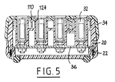
- a cover made of rigid material 110 which covers the membrane 90 and which is fixed to the upper half-case 20 by the ends 112 and 114 on its two sides which are fitted onto the body of the upper half-casing 20.
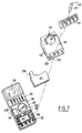
- the removable cover 110 has an end portion 120 which extends beyond the contour 44 of the cavity 46 to extend, when in position on the upper half-housing 20, to the above the sockets 32 which allow the connection of male plugs of the type of plug 122 shown diagrammatically in FIG. 7.
- This part 120 of the cover 110 comprises a series of four openings 124 which allow the connection of the test lead 127 fitted to the male plug 122 in the socket 32 arranged opposite the orifice 124.
- the four holes 124 are of course arranged symmetrically opposite four sockets 32 to allow connection in different measurement positions.
- the removable cover 110 also includes indications 126 allowing the user to identify the position of the button 128 of the control switch 28 in order to choose the range of use of the measuring device.
- the button 28 passes through the removable cover 110 by a circular recess 130 formed in the latter.
- the battery compartment 46 is delimited by a side wall 132 whose profile corresponds to that of the contour of the groove 92 and by a bottom wall 134, these two walls 132 and 134 having come integrally with the monobloc piece constituting the half upper case 20.
- the bottom wall 134 has openings 136 and 138 allowing in particular the passage of the members electrical connection 140 and 142 of fuses 48 and 50, as well as two openings 144 allowing the passage of connection terminals 145 for the electrical connection of battery 47.
- a foam sealing membrane 146 is provided, which is disposed between the lower face of the bottom 134 and the upper face of the main circuit plate. printed 36.
- the foam sealing membrane 146 has slots which allow the connection members 140, 142 and the terminals 145 for connection to the battery 47 to pass through it in a sealed manner.
- the user begins by disconnecting the male plugs 122 which are possibly in place in the sockets 32 and which pass through the safety device 34, if the measuring device is equipped with such a device, and the orifices 124 of the removable cover 110 .
- the latter comprises, since its opening of introduction 150, two successive cutouts 152 and 154 which allow the introduction of '' a fuse 48 with a diameter corresponding to that of the circular opening 152 or that of the circular opening 154.
- This characteristic advantageously makes it possible to market the same device in countries having different standardizations as to the diameters and sizes of the fuses to be used, for example 8 x 32 mm or 6.3 x 32 mm fuses.
- the battery 47 is a 9 Volt parallelepiped battery known under the standard reference 6LF22.
- the housing of the measuring device which has just been described with the arrangement of the battery compartment accessible from the functional control and use face is such that, in normal use and maintenance, the user has not never open the main housing and only needs to access compartment 46 in which are arranged battery 47 and fuses 48 and 50.
- the lower half-housing 22 is equipped with a stand 200 which is articulated around an axis 202 to allow the device to be used in an inclined position, for example relative to a plane of horizontal work.
- the free end 204 of the stand is bevelled so as to have a reduced thickness similar to that of the tip of a screwdriver.
- the stand which is easily removable, can thus be detached from the housing of the device to form a disassembly tool.
- the user can in fact advantageously use the beveled end 204 by introducing it into the joint plane 24, under the ends 112 and 114 of the cover 110.
- the stand 200 being made of the same thermoplastic material as the housings and the covers, it constitutes a non-aggressive tool for these elements, which prevents their accidental deterioration.
Description
La présente invention est relative à un appareil de mesure électrique du type comportant un boîtier dont une face fonctionnelle regroupe les organes de commande et d'utilisation, et une source de tension comportant au moins une pile électrique disposée à l'intérieur d'un compartiment du boîtier auquel on accède par une ouverture fermée par un couvercle amovible. Le compartiment de pile peut également recevoir des fusibles de protection de l'appareil.The present invention relates to an electrical measuring device of the type comprising a box, one functional face of which combines the control and use members, and a voltage source comprising at least one electric battery disposed inside a compartment. of the housing which is accessed through an opening closed by a removable cover. The battery compartment can also receive device protection fuses.
On connaît de nombreux appareils électriques de ce type tels que par exemple des récepteurs radio ou des appareils de mesure électrique dans lesquels le compartiment de pile est aménagé dans la face du boîtier qui est opposée à la face fonctionnelle, c'est-a-dire la face arrière dans le cas d'un récepteur de radio ou la face inférieure dans le cas d'un appareil de mesure. Dans ce type d'appareil l'ensemble des composants électroniques est généralement aménagé sur une plaque de circuit imprimé.Many electrical devices of this type are known, such as, for example, radio receivers or electrical measuring devices in which the battery compartment is arranged in the face of the housing which is opposite to the functional face, that is to say the back side in the case of a radio receiver or the bottom side in the case of a measuring device. In this type of device, all of the electronic components are generally arranged on a printed circuit board.
Etant donné la grande densité de composants électroniques il est souhaitable de pouvoir disposer de la plus grande surface possible de circuits imprimés tant pour permettre une simplification du tracé des circuits, que pour permettre un aménagement logique des différents composants, correspondant à différentes fonctions de l'appareil, sur la plaque principale de circuit imprimé.Given the high density of electronic components it is desirable to be able to have the largest possible surface of printed circuits both to allow a simplification of the layout of the circuits, and to allow a logical arrangement of the different components, corresponding to different functions of the device, on the main printed circuit board.
On constate que l'aménagement du boîtier de pile sur la face opposée à la face fonctionnelle nécessite de prévoir une découpe de la plaque de circuit imprimé correspondant à l'encombrement du compartiment de pile. On comprend aisément que cette découpe correspond à une surface perdue de circuit imprimé dont il est souhaitable de pouvoir disposer notamment pour la conception d'appareils électriques modernes intégrant des fonctions électroniques de plus en plus nombreuses.It can be seen that the arrangement of the battery case on the face opposite to the functional face necessitates a cutout of the printed circuit board corresponding to the size of the battery compartment. It is easy to understand that this cut corresponds to a lost surface of the printed circuit which it is desirable to be able to have in particular for the design of electrical devices. modern integrating more and more electronic functions.
Il a déjà été proposé dans le document EP-A-0100 144 de former l'ouverture dans la face fonctionnelle.It has already been proposed in document EP-
Cette conception permet de disposer de la totalité de la surface de la plaque principale de circuit imprimé qui peut s'étendre dans le fond de l'appareil et posséder ainsi un contour sensiblement complémentaire de celui de la pièce constituant le demi-boîtier de fond de l'appareil.This design makes it possible to have the entire surface of the main printed circuit board which can extend into the bottom of the device and thus have a contour substantially complementary to that of the part constituting the bottom half-housing of the device.
Dans le cas où l'appareil électrique est un appareil de mesure électrique l'aménagement du compartiment de pile sur la face fonctionnelle supérieure du boîtier doit également permettre d'ajouter une grande sécurité d'utilisation de l'appareil.In the case where the electrical device is an electrical measuring device, the arrangement of the battery compartment on the upper functional face of the housing must also make it possible to add great safety in the use of the device.
En effet dans les conceptions classiques selon lesquelles le boîtier est dans la face inférieure il est possible que l'utilisateur accède à la pile électrique ou aux fusibles sans avoir préalablement débranché les cordons de mesure qui sont enfichés dans des douilles correspondantes prévues sur la face fonctionnelle.Indeed, in the conventional designs according to which the housing is in the lower face, it is possible that the user has access to the electric battery or to the fuses without having previously disconnected the test leads which are plugged into corresponding sockets provided on the functional face. .
Une telle opération présente un grand danger pour l'utilisateur qui, par l'intermédiaire des bornes de contact de la pile électrique risque de recevoir une décharge de courant dont la tension peut, sur ce type d'appareil et en fonction de la mesure électrique réalisée, atteindre 1000 Volts.Such an operation presents a great danger for the user who, via the contact terminals of the electric battery risks receiving a current discharge whose voltage can, on this type of device and depending on the electrical measurement achieved, reach 1000 Volts.
Afin de remédier à cet inconvénient l'invention propose un appareil de mesure électrique caractérisé en ce que l'appareil est du type comportant sur sa face fonctionnelle une série de fiches femelles de connexion électrique permettant le raccordement d'un fil électrique dont l'extrémité est équipée d'une fiche mâle complémentaire, et en ce que le couvercle amovible comporte une série d'orifices agencées en vis-à-vis de la série de fiches femelles, de manière à permettre le passage de l'élément de contact électrique de la fiche mâle en vue de son introduction dans la fiche femelle et à empêcher le démontage du couvercle lorsque la fiche mâle est en position enfichée.In order to remedy this drawback, the invention provides an electrical measuring device characterized in that the device is of the type comprising on its functional face a series of female electrical connection plugs allowing the connection of an electrical wire whose end is equipped with an additional male plug, and in that the removable cover comprises a series of orifices arranged opposite the series of female plugs, so as to allow the passage of the electrical contact element of the male plug for its introduction into the female plug and to prevent dismantling of the cover when the male plug is in the inserted position.
Selon un mode particulier de réalisation de l'invention le couvercle amovible comporte des indications pour le repérage de la position d'un commutateur de commande de l'appareil.According to a particular embodiment of the invention, the removable cover includes indications for locating the position of a control switch for the device.
Cette caractéristique permet encore d'améliorer la sécurité de l'appareil de mesure pour le cas où l'utilisateur rebrancherait les cordons de mesure électrique sans avoir remis en place le couvercle amovible, il lui serait alors impossible d'utiliser l'appareil de mesure puisqu'il ne pourrait pas positionner le commutateur de commande en l'absence des indications nécessaires à son utilisation.This characteristic further improves the safety of the measuring device in the event that the user reconnects the electrical measuring cords without replacing the removable cover, it would then be impossible for him to use the measuring device. since it could not position the control switch in the absence of the indications necessary for its use.
Selon d'autres modes particuliers de réalisation de l'invention :
- le commutateur est équipé d'un bouton de commande qui se déplace dans un évidement du couvercle ;
- le compartiment de pile est délimité par une paroi latérale et par un fond traversé par des moyens de raccordement électrique de la source de tension avec un circuit électrique agencé dans la cavité interne du boîtier ;
- l'étanchéité du compartiment par rapport a la cavité interne du boîtier est assurée au moyen d'une membrane d'étanchéité agencée entre la face interne du fond du compartiment et une face d'appui disposée a l'intérieur du boîtier, la membrane étant traversée par les moyens de raccordement électrique ;
- la face d'appui est une face d'une plaque de circuit imprimé qui s'étend sous le fond du compartiment ;
- le compartiment de pile reçoit également au moins un fusible de protection ; et
- l'ouverture du compartiment est obturée par une membrane d'étanchéité disposée entre le boîtier de commande et le couvercle amovible.
- the switch is fitted with a control button which moves in a recess in the cover;
- the battery compartment is delimited by a side wall and by a bottom traversed by means of electrical connection of the voltage source with an electrical circuit arranged in the internal cavity of the housing;
- the compartment is sealed relative to the internal cavity of the housing is ensured by means of a sealing membrane arranged between the internal face of the bottom of the compartment and a bearing face disposed inside the housing, the membrane being crossed by the electrical connection means;
- the bearing face is a face of a printed circuit board which extends under the bottom of the compartment;
- the battery compartment also receives at least one protective fuse; and
- the opening of the compartment is closed by a waterproofing membrane arranged between the control unit and the removable cover.
D'autres modes particuliers de réalisation et avantages de l'invention apparaîtront à la lecture de la description détaillée qui va suivre pour la compréhension de laquelle on se reportera aux dessins annnexés :
- la figure 1 est une vue de dessus de la face fonctionnelle d'utilisation et de commande d'un appareil de mesure électrique réalisé conformément aux enseignements de l'invention ;
- la figure 2 est une vue de dessus de la pièce monobloc constituant le demi-boîtier supérieur de l'appareil de la figure 1 ;
- la figure 3 est une vue en coupe de l'appareil de la figure 1 selon la ligne 3-3 de la figure 2 ;
- la figure 4 est une vue en coupe selon la ligne 4-4 de la figure 3 ;
- la figure 5 est une vue en coupe selon la ligne 5-5 de la figure 3 ;
- la figure 6 est une vue en coupe de l'appareil de la figure 1 selon la ligne 6-6 de la figure 2 ; et
- la figure 7 est une vue simplifiée en perspective éclatée permettant d'illustrer l'accès au boîtier de pile de l'appareil de mesure.
- Figure 1 is a top view of the functional side of use and control of an electrical measuring device produced in accordance with the teachings of the invention;
- Figure 2 is a top view of the single piece constituting the upper half-casing of the device of Figure 1;
- Figure 3 is a sectional view of the apparatus of Figure 1 taken along line 3-3 of Figure 2;
- Figure 4 is a sectional view along line 4-4 of Figure 3;
- Figure 5 is a sectional view along line 5-5 of Figure 3;
- Figure 6 is a sectional view of the apparatus of Figure 1 taken along line 6-6 of Figure 2; and
- Figure 7 is a simplified exploded perspective view to illustrate access to the battery housing of the measuring device.
L'appareil de mesure électrique représenté aux figures 1 à 7 est un appareil classique dont le boîtier de forme générale parallélépipédique rectangle est réalisé en deux demi-boîtiers 20 et 22 entre lesquels on discerne un décrochement 24 marquant le plan de joint.The electrical measuring device shown in Figures 1 to 7 is a conventional device whose generally rectangular parallelepiped shape is made of two half-
On reconnaît également l'écran 26 d'un afficheur numérique, le commutateur de gamme 28, un clavier de commande 30, ainsi qu'une série 32 de quatre douilles ou fiches femelles permettant le raccordement de cordons de mesure (non représentés aux figures 1 à 6) qui sont généralement terminés par des fiches mâles, côté appareil, et des sondes, côté point de mesure.We also recognize the
Aux figures 3 à 7, on a également représenté un dispositif 34 de verrouillage qui permet de retenir les fiches de connexion électrique enfichées dans l'appareil de mesure conformément aux caractéristiques de la demande de brevet FR-A-2.587.849 au contenu de laquelle on pourra avantageusement se reporter. Pour des raisons de clarté, le dispositif 34 de verrouillage n'est pas représenté à la figure 1.In Figures 3 to 7, there is also shown a
L'appareil comporte un circuit électronique principal qui est monté sur une plaque rectangulaire principale de circuit imprimé 36 ainsi que sur une plaque secondaire 39 qui sont agencées a l'intérieur de la cavité interne 38 du boîtier. Les principaux composants électroniques et circuits de commutation de l'appareil ne sont pas représentés sur les figures.The apparatus comprises a main electronic circuit which is mounted on a main rectangular printed
Comme on peut le constater sur les figures, la plaque principale de circuit imprimé 36 possède un contour rectangulaire sensiblement égal à celui des deux demi-boîtiers et elle présente ainsi une surface maximale pour la réalisation des circuits de l'appareil.As can be seen in the figures, the main printed
Sur sa face supérieure fonctionnelle qui regroupe les organes de commande et d'utilisation 26, 28, 30 et 32, le demi-boîtier supérieur 20 comporte une ouverture 44 s'ouvrant vers le haut pour permettre l'accès à un compartiment 46 dans lequel sont agencés une pile électrique 47 et des fusibles de protection 48 et 50.On its functional upper face which groups the control and use
L'étanchéité du compartiment de pile 46, par rapport a l'extérieur, est assurée au moyen d'une membrane pleine continue et souple 90. La membrane 90 s'étend dans un plan et délimite un contour externe sensiblement rectangulaire qui correspond au contour de l'ouverture 44 d'accès au compartiment de pile 46. Le contour 44 est délimité par une gorge continue 92 dans laquelle est reçu un joint d'étanchéité de section circulaire 94 venu de matière avec la membrane 90.The tightness of the
Afin de faciliter l'enlèvement par l'utilisateur de la membrane souple d'étanchéité 90, celle-ci est pourvue d'une patte de préhension 106 venue de matière avec la membrane 90 et qui est reçue, lorsqu'elle est en place, dans un logement en creux 108 formé dans la face supérieure du demi-boîtier supérieur 20.In order to facilitate the removal by the user of the
L'accès au boîtier de pile est également protégé par un couvercle en matériau rigide 110 qui recouvre la membrane 90 et qui est fixé au demi-boîtier supérieur 20 par les extrémités 112 et 114 de ses deux côtés qui sont emboitées sur le corps du demi-boîtier supérieur 20.Access to the battery case is also protected by a cover made of
Conformément à l'invention, le couvercle amovible 110 comporte une partie d'extrémité 120 qui se prolonge au-delà du contour 44 de la cavité 46 pour s'étendre, lorsqu'il est en position sur le demi-boîtier supérieur 20, au-dessus des douilles 32 qui permettent le raccordement de fiches mâle du type de la fiche 122 schématisée à la figure 7.According to the invention, the
Cette partie 120 du couvercle 110 comporte une série de quatre orifices 124 qui permettent le raccordement du cordon de mesure 127 équipant la fiche mâle 122 dans la douille 32 agencée en vis-à-vis de l'orifice 124.This
Dans le mode de réalisation représenté, les quatre orifices 124 sont bien entendu agencés symétriquement en vis-à-vis de quatre douilles 32 pour permettre le raccordement dans différentes positions de mesure.In the embodiment shown, the four
Le couvercle amovible 110 comporte également des indications 126 permettant à l'utilisateur de repérer la position du bouton 128 du commutateur de commande 28 afin de choisir la gamme d'utilisation de l'appareil de mesure. Le bouton 28 traverse le couvercle amovible 110 par un évidement circulaire 130 formé dans ce dernier.The
Le compartiment de pile 46 est délimité par une paroi latérale 132 dont le profil correspond à celui du contour de la gorge 92 et par une paroi de fond 134, ces deux parois 132 et 134 étant venues de matière avec la pièce monobloc constituant le demi-boîtier supérieur 20.The
La paroi de fond 134 comporte des ouvertures 136 et 138 permettant notamment le passage des organes de connexion électrique 140 et 142 des fusibles 48 et 50, ainsi que deux ouvertures 144 permettant le passage des bornes de raccordement 145 pour le raccordement électrique de la pile 47.The
Afin d'assurer l'étanchéité entre le compartiment pile et la cavité interne du boîtier 38, il est prévu une membrane d'étanchéité en mousse 146 qui est disposée entre la face inférieure du fond 134 et la face supérieure de la plaque principale de circuit imprimé 36.In order to ensure sealing between the battery compartment and the internal cavity of the
La membrane d'étanchéité 146 en mousse comporte des fentes qui permettent aux organes de connexion 140, 142 et aux bornes 145 de raccordement à la pile 47 de la traverser de manière étanche.The
On décrira maintenant le mode d'accès au compartiment de pile et fusibles pour procéder par exemple au remplacement de l'un de ces éléments, en se reportant notamment à la figure 7.We will now describe the mode of access to the battery and fuse compartment to proceed, for example, with the replacement of one of these elements, with particular reference to FIG. 7.
L'utilisateur commence par débrancher les fiches mâles 122 qui sont éventuellement en place dans les douilles 32 et qui traversent le dispositif 34 de sécurité, si l'appareil de mesure est équipé d'un tel dispositif, et les orifices 124 du couvercle amovible 110.The user begins by disconnecting the male plugs 122 which are possibly in place in the
L'utilisateur ôte ensuite le dispositif 34 de sécurité qui est emboité élastiquement sur le couvercle amovible 110 puis ce dernier élément qui est emboité sur le demi-boîtier supérieur 20. Si l'utilisateur n'a pas préalablement ôté les fîches mâles 122 et le dispositif 34 de sécurité il lui est impossible d'enlever le couvercle amovible 110.The user then removes the
L'utilisateur n'a plus ensuite qu'a ôter la membrane d'étanchéité souple 90 pour accéder au compartiment 46 et procéder aux opérations de vérification et de remplacement de la pile 47 et/ou des fusibles 48 et 50.The user then only has to remove the
La remise en place des éléments se fait dans l'ordre inverse de celui qui vient d'être indiqué pour le démontage.The elements are replaced in the reverse order to that just indicated for disassembly.
On constate également que si l'utilisateur vient à remettre en place les fiches mâles sans avoir remis le couvercle amovible 110, il est pratiquement dans l'impossibilité d'utiliser l'appareil de mesure puisqu'il n'y a plus de repères 126 en regard du bouton de commande 128 du commutateur 28.It is also noted that if the user comes to replace the male plugs without having replaced the
Afin de permettre le montage indifférent de fusibles de calibres différents dans des mêmes organes porte-fusible telles que la pièce 140, on constate que celle-ci comporte depuis son ouverture d'introduction 150 deux découpes successives 152 et 154 qui permettent l'introduction d'un fusible 48 d'un diamètre correspondant à celui de l'ouverture circulaire 152 ou à celui de l'ouverture circulaire 154. Cette caractéristique permet avantageusement de commercialiser le même appareil dans des pays possédant différentes normalisations quant aux diamètres et aux calibres des fusibles à utiliser, par exemple des fusibles 8 x 32 mm ou 6,3 x 32 mm.In order to allow the indifferent mounting of fuses of different calibers in the same fuse holder members such as the
Dans le mode de réalisation représenté la pile 47 est une pile 9 Volts parallélépipédique connue sous la référence normalisée 6LF22.In the embodiment shown, the
Le boîtier de l'appareil de mesure qui vient d'être décrit avec l'agencement du compartiment de pile accessible depuis la face fonctionnelle de commande et d'utilisation est tel que, en utilisation et en maintenance normale, l'utilisateur n'a jamais à ouvrir le boîtier principal et n a besoin que d'accéder au compartiment 46 dans lequel sont-disposés la pile 47 et les fusibles 48 et 50.The housing of the measuring device which has just been described with the arrangement of the battery compartment accessible from the functional control and use face is such that, in normal use and maintenance, the user has not never open the main housing and only needs to access
D'une manière connue en soi, le demi-boîtier inférieur 22 est équipé d'une béquille 200 qui est articulée autour d'un axe 202 pour permettre d'utiliser l'appareil en position inclinée, par exemple par rapport à un plan de travail horizontal.In a manner known per se, the lower half-
Selon une caractéristique nouvelle, l'extrémité libre 204 de la béquille est biseautée de manière à présenter une épaisseur réduite similaire à celle de la pointe d'un tournevis. La béquille qui est démontable aisément, peut ainsi être désolidarisée du boîtier de l'appareil pour former un outil de démontage.According to a new characteristic, the
L'utilisateur peut en effet avantageusement utiliser l'extrémité biseautée 204 en l'introduisant dans le plan de joint 24, sous les extrémités 112 et 114 du couvercle 110.The user can in fact advantageously use the
Le béquille 200 étant réalisée dans le même matériau thermoplastique que les boîtiers et les couvercles, elle constitue un outil non agressif pour ces éléments, ce qui évite leur détérioration accidentelle.The
Claims (8)
- Electrical measuring appliance of the type having a housing (20), one functional face of which groups together the control and operating components (26, 28, 30, 32), and a voltage source comprising at least one electrical battery (47) disposed inside a compartment (46) in the housing (20), to which access is gained via an opening (44) formed in the said functional face and closed by means of a removable cover (110), characterised in that the appliance is of the type having, on its functional face, a series of female electrical connection sockets (32) enabling an electric wire (127) to be connected, the end of which is equipped with a matching male plug (122), and in that the removable cover (110) has a series of orifices (124) arranged opposite the series of female sockets (32), so as to allow the electrical contact part of the male plug to pass for the purpose of inserting it into the female socket and preventing the cover being removed when the male plug is in the plugged-in position.
- Electrical measuring appliance according to Claim 1, characterised in that the cover (110) has indications (126) for marking the position of a control switch (28) for the appliance.
- Electrical measuring appliance according to Claim 2, characterised in that the switch (28) is equipped with a control knob (128) which moves in a recess (130) in the cover.
- Electrical measuring appliance according to any one of the preceding claims, characterised in that the compartment (46) is defined by a side wall (132) and by a bottom (134), through which pass means (140, 142, 145) for connecting the voltage source electrically to an electrical circuit arranged in the inner cavity (38) of the housing.
- Electrical measuring appliance according to Claim 4, characterised in that the sealing of the compartment (46) with respect to the inner cavity (38) of the housing is obtained by mains of a sealing diaphragm (146) arranged between the inner face of the said bottom (134) and a bearing face disposed inside the housing, and in that the said diaphragm has the said electrical means passing through it.
- Electrical measuring appliance according to Claim 5, characterised in that the said bearing face is a face of a printed circuit board (36) which extends underneath the bottom (134) of the compartment (46).
- Electrical measuring appliance according to any one of the preceding claims, characterised in that at least one protection fuse (48, 50) is disposed in the battery compartment (46).
- Electrical measuring appliance according to any one of the preceding claims, characterised in that the opening (44) in the compartment is closed off by a sealing diaphragm (90) disposed between the housing (20) and the removable cover (110).
Applications Claiming Priority (2)
| Application Number | Priority Date | Filing Date | Title |
|---|---|---|---|
| FR8812602 | 1988-09-27 | ||
| FR8812602A FR2637153B1 (en) | 1988-09-27 | 1988-09-27 | ELECTRICAL DEVICE WITH IMPROVED BATTERY COMPARTMENT |
Publications (2)
| Publication Number | Publication Date |
|---|---|
| EP0366507A1 EP0366507A1 (en) | 1990-05-02 |
| EP0366507B1 true EP0366507B1 (en) | 1993-10-27 |
Family
ID=9370428
Family Applications (1)
| Application Number | Title | Priority Date | Filing Date |
|---|---|---|---|
| EP89402604A Expired - Lifetime EP0366507B1 (en) | 1988-09-27 | 1989-09-22 | Electrical apparatus with improved cell compartment |
Country Status (4)
| Country | Link |
|---|---|
| US (1) | US5084670A (en) |
| EP (1) | EP0366507B1 (en) |
| DE (1) | DE68910269T2 (en) |
| FR (1) | FR2637153B1 (en) |
Cited By (1)
| Publication number | Priority date | Publication date | Assignee | Title |
|---|---|---|---|---|
| DE4438239C1 (en) * | 1994-10-26 | 1996-06-05 | Mueller & Weigert | Battery operated measuring device, in particular a clamp application device |
Families Citing this family (12)
| Publication number | Priority date | Publication date | Assignee | Title |
|---|---|---|---|---|
| GB2259574B (en) * | 1991-09-12 | 1995-08-30 | Heme Int Ltd | Measuring devices |
| JPH07270457A (en) * | 1994-04-01 | 1995-10-20 | Seiko Epson Corp | Digital multimeter |
| US5834935A (en) * | 1997-03-18 | 1998-11-10 | Tektronix, Inc. | Hand held instrument with safety locked battery compartment |
| US5920188A (en) * | 1997-11-25 | 1999-07-06 | Fluke Corporation | Voltage measurement instrument having transient overvoltage input protection |
| AU2002360497A1 (en) | 2001-12-06 | 2003-06-23 | Rast Associates, Llc | Expandable and contractible keyboard device |
| WO2003050665A1 (en) * | 2001-12-06 | 2003-06-19 | Rast Associates, Llc | Articulated, rotatable expandable and contractive keyboard device |
| DE102005036037A1 (en) * | 2005-08-01 | 2007-02-08 | Robert Bosch Gmbh | gauge |
| US7830135B2 (en) * | 2007-08-14 | 2010-11-09 | Fluke Corporation | Digital multimeter having housing sealing arrangement |
| US7654857B2 (en) * | 2007-08-14 | 2010-02-02 | Fluke Corporation | Digital multimeter having sealed input jack detection arrangement |
| US7911200B2 (en) * | 2007-08-14 | 2011-03-22 | Fluke Corporation | Digital multimeter having case panel structure |
| DE202009012059U1 (en) * | 2009-09-07 | 2011-02-03 | Conrad Electronic Se | gauge |
| USD890617S1 (en) * | 2019-01-22 | 2020-07-21 | Chauvin Arnoux | Ohmmeter |
Family Cites Families (16)
| Publication number | Priority date | Publication date | Assignee | Title |
|---|---|---|---|---|
| US1739142A (en) * | 1924-04-10 | 1929-12-10 | Thomas E Murray Jr | Switch-box cover and attachment |
| FR1533837A (en) * | 1967-08-09 | 1968-07-19 | Eastman Kodak Co | Sophisticated body, especially for cameras |
| US3763752A (en) * | 1972-04-14 | 1973-10-09 | Perfect Film & Chem Corp | Camera with built-in stroboscopic flash |
| US3881961A (en) * | 1973-08-02 | 1975-05-06 | Motorola Inc | Battery housing |
| US4317628A (en) * | 1979-08-06 | 1982-03-02 | Canon Kabushiki Kaisha | Electric circuit protection device for camera |
| US4297635A (en) * | 1979-11-19 | 1981-10-27 | General Electric Company | Watthour meter and battery retaining apparatus therefor |
| US4439736A (en) * | 1981-05-13 | 1984-03-27 | Cable Electric Products, Inc. | Battery testing system |
| DE3382783T2 (en) * | 1982-07-22 | 1995-07-27 | Texas Instruments Inc | Keyboard for an electronic device. |
| DE3344311A1 (en) * | 1983-12-07 | 1985-06-20 | Ruhrkohle Ag, 4300 Essen | MEASURING DEVICE, IN PARTICULAR RUN TIME MEASURING DEVICE FOR LOCATING CABLE ERRORS |
| JPS61120265A (en) * | 1984-11-16 | 1986-06-07 | Canon Inc | Electronic device |
| JPS61278830A (en) * | 1985-06-04 | 1986-12-09 | Konishiroku Photo Ind Co Ltd | Camera with built-in stroboscope |
| US4713609A (en) * | 1985-09-05 | 1987-12-15 | General Electric Company | Battery backup installation for electric meter |
| FR2587849B1 (en) * | 1985-09-23 | 1989-11-10 | Itt Composants Instr | PLUG LOCKING DEVICE FOR MEASURING APPARATUS |
| US4752539A (en) * | 1986-11-10 | 1988-06-21 | Spectra-Physics, Inc. | Battery holder for electronic apparatus |
| US4847170A (en) * | 1988-09-09 | 1989-07-11 | Pulse Electronics, Inc. | Battery container and adapter |
| US4991058A (en) * | 1989-11-09 | 1991-02-05 | Grid Systems Corporation | Card housing attachment for a portable computer |
-
1988
- 1988-09-27 FR FR8812602A patent/FR2637153B1/en not_active Expired - Fee Related
-
1989
- 1989-09-20 US US07/409,891 patent/US5084670A/en not_active Expired - Fee Related
- 1989-09-22 DE DE89402604T patent/DE68910269T2/en not_active Expired - Fee Related
- 1989-09-22 EP EP89402604A patent/EP0366507B1/en not_active Expired - Lifetime
Cited By (1)
| Publication number | Priority date | Publication date | Assignee | Title |
|---|---|---|---|---|
| DE4438239C1 (en) * | 1994-10-26 | 1996-06-05 | Mueller & Weigert | Battery operated measuring device, in particular a clamp application device |
Also Published As
| Publication number | Publication date |
|---|---|
| FR2637153B1 (en) | 1993-03-26 |
| DE68910269D1 (en) | 1993-12-02 |
| US5084670A (en) | 1992-01-28 |
| FR2637153A1 (en) | 1990-03-30 |
| DE68910269T2 (en) | 1994-02-24 |
| EP0366507A1 (en) | 1990-05-02 |
Similar Documents
| Publication | Publication Date | Title |
|---|---|---|
| EP0366507B1 (en) | Electrical apparatus with improved cell compartment | |
| EP2727192B1 (en) | Use of a socket and electrical unit | |
| EP0987803B1 (en) | Protection device for electric installations against alimentation disturbances | |
| EP0580505B1 (en) | Adaptation system between an antenna connector and a socket of a radio telephone | |
| WO2018167181A1 (en) | Connector assembly | |
| FR2777120A1 (en) | RING FOR LOCATING THE USE VOLTAGE OF AN ELECTRICAL CONNECTION ELEMENT | |
| EP3840136B1 (en) | Mechanism for electrical equipment, associated electrical assembly and electrical equipment | |
| FR2920256A1 (en) | Locked socket has bushing for receiving socket, where switch is placed in assembly frame, which is connected with bushing, and insert is connected with switch by actuating device | |
| FR3045700B1 (en) | ARTICULATED ROTATION DEVICE HAVING AN ELECTRICAL CONNECTION SYSTEM | |
| EP3471124B1 (en) | Power supply switch for a protection module and protection module comprising such a switch | |
| EP1033735B1 (en) | Electronic trip device comprising a removable long-time-delay module with a conection/disconnection function | |
| EP0709685A1 (en) | Electrical measuring apparatus with battery compartment with access protection | |
| FR2716756A1 (en) | Improved power supply and control assembly for a motor vehicle alternator. | |
| EP3009812B2 (en) | Sensor device with modular constitution and industrial system comprising same | |
| EP1278224A1 (en) | Electrical terminal arrangement for two, next to each other, rail-mounted electrical devices | |
| EP0418136A1 (en) | High voltage connection for an ignition coil, particularly for an internal combustion engine of an automotive vehicle | |
| EP3159906B1 (en) | Electrical switching apparatus including a switching mechanism and at least one auxiliary module | |
| FR2637152A1 (en) | Sealed housing, especially for an electrical apparatus | |
| FR2490060A1 (en) | Replaceable proximity limit switch - has cylindrical housing that plugs into fixed box clamp and may be rotated | |
| FR3069715A1 (en) | MULTI-APPARATUS BLOCK WITH ANTI-HOLD-A-FALSE SUPPORT ELEMENT | |
| EP0797271A1 (en) | Base for current socket | |
| WO2006063954A1 (en) | Electric connection device for a polyphase electric meter | |
| CA2932321C (en) | Electrical cut-off device for accumulator batteries | |
| FR2746231A1 (en) | Electronic card with inbuilt battery supply e.g. for opening and closing doors and for alarm systems connected in parallel with original supply battery welded to card printed circuit connections. | |
| WO2023274949A1 (en) | Connection terminal and associated electrical apparatus |
Legal Events
| Date | Code | Title | Description |
|---|---|---|---|
| PUAI | Public reference made under article 153(3) epc to a published international application that has entered the european phase |
Free format text: ORIGINAL CODE: 0009012 |
|
| AK | Designated contracting states |
Kind code of ref document: A1 Designated state(s): DE FR GB IT NL |
|
| 17P | Request for examination filed |
Effective date: 19900728 |
|
| 17Q | First examination report despatched |
Effective date: 19910906 |
|
| GRAA | (expected) grant |
Free format text: ORIGINAL CODE: 0009210 |
|
| AK | Designated contracting states |
Kind code of ref document: B1 Designated state(s): DE FR GB IT NL |
|
| PG25 | Lapsed in a contracting state [announced via postgrant information from national office to epo] |
Ref country code: IT Free format text: LAPSE BECAUSE OF FAILURE TO SUBMIT A TRANSLATION OF THE DESCRIPTION OR TO PAY THE FEE WITHIN THE PRESCRIBED TIME-LIMIT;WARNING: LAPSES OF ITALIAN PATENTS WITH EFFECTIVE DATE BEFORE 2007 MAY HAVE OCCURRED AT ANY TIME BEFORE 2007. THE CORRECT EFFECTIVE DATE MAY BE DIFFERENT FROM THE ONE RECORDED. Effective date: 19931027 Ref country code: NL Effective date: 19931027 |
|
| REF | Corresponds to: |
Ref document number: 68910269 Country of ref document: DE Date of ref document: 19931202 |
|
| GBT | Gb: translation of ep patent filed (gb section 77(6)(a)/1977) |
Effective date: 19931108 |
|
| NLV1 | Nl: lapsed or annulled due to failure to fulfill the requirements of art. 29p and 29m of the patents act | ||
| PLBE | No opposition filed within time limit |
Free format text: ORIGINAL CODE: 0009261 |
|
| STAA | Information on the status of an ep patent application or granted ep patent |
Free format text: STATUS: NO OPPOSITION FILED WITHIN TIME LIMIT |
|
| 26N | No opposition filed | ||
| REG | Reference to a national code |
Ref country code: FR Ref legal event code: TP |
|
| REG | Reference to a national code |
Ref country code: GB Ref legal event code: 732E |
|
| REG | Reference to a national code |
Ref country code: FR Ref legal event code: TP |
|
| PGFP | Annual fee paid to national office [announced via postgrant information from national office to epo] |
Ref country code: FR Payment date: 20000831 Year of fee payment: 12 |
|
| PGFP | Annual fee paid to national office [announced via postgrant information from national office to epo] |
Ref country code: DE Payment date: 20000918 Year of fee payment: 12 |
|
| PGFP | Annual fee paid to national office [announced via postgrant information from national office to epo] |
Ref country code: GB Payment date: 20000920 Year of fee payment: 12 |
|
| REG | Reference to a national code |
Ref country code: GB Ref legal event code: 732E |
|
| PG25 | Lapsed in a contracting state [announced via postgrant information from national office to epo] |
Ref country code: GB Free format text: LAPSE BECAUSE OF NON-PAYMENT OF DUE FEES Effective date: 20010922 |
|
| REG | Reference to a national code |
Ref country code: GB Ref legal event code: IF02 |
|
| PG25 | Lapsed in a contracting state [announced via postgrant information from national office to epo] |
Ref country code: DE Free format text: LAPSE BECAUSE OF NON-PAYMENT OF DUE FEES Effective date: 20020501 |
|
| GBPC | Gb: european patent ceased through non-payment of renewal fee |
Effective date: 20010922 |
|
| PG25 | Lapsed in a contracting state [announced via postgrant information from national office to epo] |
Ref country code: FR Free format text: LAPSE BECAUSE OF NON-PAYMENT OF DUE FEES Effective date: 20020531 |
|
| REG | Reference to a national code |
Ref country code: FR Ref legal event code: ST |